EP0178484B1 - Chargeur pour canons - Google Patents
Chargeur pour canons Download PDFInfo
- Publication number
- EP0178484B1 EP0178484B1 EP85111886A EP85111886A EP0178484B1 EP 0178484 B1 EP0178484 B1 EP 0178484B1 EP 85111886 A EP85111886 A EP 85111886A EP 85111886 A EP85111886 A EP 85111886A EP 0178484 B1 EP0178484 B1 EP 0178484B1
- Authority
- EP
- European Patent Office
- Prior art keywords
- propellant charge
- projectile
- shell
- axis
- loading
- Prior art date
- Legal status (The legal status is an assumption and is not a legal conclusion. Google has not performed a legal analysis and makes no representation as to the accuracy of the status listed.)
- Expired
Links
- 239000003380 propellant Substances 0.000 claims description 103
- 238000012546 transfer Methods 0.000 claims description 13
- 230000005540 biological transmission Effects 0.000 claims 2
- 238000000034 method Methods 0.000 description 3
- 238000003780 insertion Methods 0.000 description 2
- 230000037431 insertion Effects 0.000 description 2
- 238000012423 maintenance Methods 0.000 description 2
- 238000004519 manufacturing process Methods 0.000 description 2
- 238000011161 development Methods 0.000 description 1
- 230000018109 developmental process Effects 0.000 description 1
Images


Classifications
-
- F—MECHANICAL ENGINEERING; LIGHTING; HEATING; WEAPONS; BLASTING
- F41—WEAPONS
- F41A—FUNCTIONAL FEATURES OR DETAILS COMMON TO BOTH SMALLARMS AND ORDNANCE, e.g. CANNONS; MOUNTINGS FOR SMALLARMS OR ORDNANCE
- F41A9/00—Feeding or loading of ammunition; Magazines; Guiding means for the extracting of cartridges
- F41A9/37—Feeding two or more kinds of ammunition to the same gun; Feeding from two sides
- F41A9/375—Feeding propellant charges and projectiles as separate units
-
- F—MECHANICAL ENGINEERING; LIGHTING; HEATING; WEAPONS; BLASTING
- F41—WEAPONS
- F41A—FUNCTIONAL FEATURES OR DETAILS COMMON TO BOTH SMALLARMS AND ORDNANCE, e.g. CANNONS; MOUNTINGS FOR SMALLARMS OR ORDNANCE
- F41A9/00—Feeding or loading of ammunition; Magazines; Guiding means for the extracting of cartridges
- F41A9/01—Feeding of unbelted ammunition
- F41A9/06—Feeding of unbelted ammunition using cyclically moving conveyors, i.e. conveyors having ammunition pusher or carrier elements which are emptied or disengaged from the ammunition during the return stroke
- F41A9/09—Movable ammunition carriers or loading trays, e.g. for feeding from magazines
- F41A9/10—Movable ammunition carriers or loading trays, e.g. for feeding from magazines pivoting or swinging
- F41A9/13—Movable ammunition carriers or loading trays, e.g. for feeding from magazines pivoting or swinging in a vertical plane
- F41A9/16—Movable ammunition carriers or loading trays, e.g. for feeding from magazines pivoting or swinging in a vertical plane which is parallel to the barrel axis
Definitions
- the invention relates to a charging device for guns according to the preamble of patent claim 1.
- Such a loading device for guns for the separate supply of projectiles and propellant charges in front of the breech opening of the gun barrel is known from DE-C-619 896.
- this loading device consists of a device attached to the cradle tube, which can not pivot separately but only together with the cradle tube about the vertical axis of the weapon barrel.
- this loading device it is therefore necessary to feed the projectile and the propellant charge from a bunker, preferably a ship's gun, via a complex vertical central elevator to a swiveling ammunition basket, which must be adapted to the respective weapon barrel increase by a tilting process in order to pass on the ammunition to the device on the cradle barrel.
- Due to the rigid attachment to the cradle tube however, this device is not suitable for direct removal of ammunition from a tank turret magazine, because then the weapon barrel would have to pivot back into an index position about the vertical direction axis.
- a rocker arm also attached to the cradle tube is necessary, which has a common support for one storey and Propellant receiving trough receives, the carrier needs a cradle-mounted handlebar for steering.
- the arrangement and mode of operation of the rocker and the handlebar permit a force-controlled pivoting of the projectile and the propellant charge one after the other from only one direction of rotation exclusively above the bearing of the rocker arranged on the cradle tube.
- this arrangement does not disclose any information, in particular to separately feed ammunition stored separately in armored turret magazines from removal openings at different distances to the closure opening.
- DE-A-20 27 586 discloses a device for loading projectiles and propellant charges stored separately in turrets, in which bullets and cartridges containing bullets and cartridges containing cartridges stored in separate bullet and propellant charge magazines for removal on both sides and rear of the gun barrel are space-consuming transverse conveyor tracks and for lifting the split ammunition further gripper arms are necessary. Furthermore, in order to pivot the projectile and the propellant in front of the breech opening of the gun barrel, two devices, which are arranged on both sides of the gun barrel and can be pivoted about the gun vertical direction axis, are necessary, one for taking over the projectiles and the propellant charges from the cross conveyor track to the two pivoting devices, one in the vertical plane of the gun barrel arranged longitudinal transport device is required.
- This device which consists of many individual transport devices, is complex to manufacture and requires a large amount of space, which leads to comparatively high tower silhouettes.
- This device is further designed such that the projectile and the propellant charge are arranged one behind the other and are transported together by a separate attachment device into the cargo space of the gun barrel.
- Split ammunition arranged at the same time one behind the other requires a large space to be kept behind the weapon for the loading process, which, in order to achieve a maximum pipe elevation, is not provided, for example, with a howitzer.
- a certain minimum force is required to attach the projectile, which, however, in order to avoid damage to the propellant charge, especially in the case of large pipe elevations, should not be transmitted via the propellant charge itself.
- the gun barrel Due to the two-sided arrangement of the two swivel devices, the gun barrel is difficult to access, so that maintenance is difficult and manual loading of special projectiles is not possible.
- the invention has for its object to provide a space-saving loading device behind the breech and to the side of the gun barrel, which can be pivoted independently of the pivoting movement of the cradle barrel around the gun's vertical axis and can follow the maximum elevation of the gun barrel, especially with howitzers, and a separate automatic and simple supply of a projectile and a preferably unbundled modular propellant charge, taking into account an individual dosage in length and a safe removal of the propellant charge.
- the position of the removal openings of the storey and propellant charge magazines arranged in the tank tower as well as the position of the propellant charge case for receiving the propellant charge modules from the takeout opening of the propellant charge magazine and the position of the storey charge case for receiving the projectile which can be removed from the storey magazine are on the same side of the transport arm, so that time-saving recording of the projectile and the propellant charge can be done directly from the tower magazines on only one side of the projectile tube.
- the propellant charge and the storey charging cradle each have a separately and firmly connected pivot lever which are pivotally arranged on a common with the transfer arm and directly connected to this axis, a parallel stacked and space-saving transport position during the pivoting process of the projectile and the propellant charge on the transfer arm.
- This also advantageously results in only a comparatively small space requirement behind the breech block of the gun, on the basis of whose maximum angle of elevation of the gun barrel, for example in the case of howitzers, can be achieved.
- the common axis of the propellant charge cradle and the projectile charge cradle also allow simultaneous removal of the projectile and the propellant charge from overlying removal positions of the propellant charge and projectile magazine, from which, after the transfer arm has been pivoted, the projectile charge cradle from above and the propellant charge cradle from below in front of the breech opening of the gun barrel is pivotable.
- This pivoting option allows the distances of the removal positions from the storey and propellant charge magazines to be varied and enables different positions of the propellant charge cradle and storey charge cradle to accommodate the modular propellant charges and projectiles. From the removal positions, the propellant charge can be picked up from below by the propellant charge charging cradle and the projectile can be picked up from the side by the bullet charging cradle.
- a particularly large space saving is achieved when the propellant charge cradle is pivotally arranged on the storey cradle.
- the swivel arm of the propellant charge cradle can advantageously be shorter than the swivel arm of the storey charging cradle.
- This arrangement also allows a position of the projectile charging cradle between the pivot axes of the projectile charging cradle and the propellant charge shell, whereby small differences in height of the projectile and propellant charge removal positions can be achieved.
- the arrangement of an unlocking device of the propellant charge magazine makes it possible to meter the propellant charge individually in terms of length, and the modular propellant charge can be supplied in a space-saving manner transversely or in the axial direction to the propellant charge cradle.
- FIG. 1 and 2 show a rotatably mounted gun turret 25 with a gun barrel 5 which can be pivoted about the vertical axis 4.
- the gun turret 25 contains a projectile magazine 12 on the rear, in which projectiles 1 are mounted parallel to the plane of the projectile tube axis 17 and laterally offset to the gun tube a propellant charge magazine 13 divided into compartments 21 for storing unbundled modular propellant charges 3.
- a charging device 26 is arranged on one side of the gun barrel 5, which is attached to a transfer arm pivotable about the vertical direction axis 4 and one Contains charging cradle 8 for the transport of the propellant charge 3 and a charging cradle 9 for the transport of a projectile 1.
- Both charging cradles 8, 9 are arranged on a common pivot axis 15 connected to the transfer arm 6.
- the projectiles 1 are pushed into the charging cradle 9 parallel to the projectile tube axis 17 by a pushing device, not shown, while the propellant charge modules 2 located in a collecting trough 18 (FIG. 6) are pushed into the charging cradle 8 by a driving device 20 (FIG. 8).
- the transfer arm 6 pivots with a received projectile 1 and the propellant charge 3 into the position of the gun barrel oriented at an elevation angle a, 20 elevation angles a greater than 50 ° being possible due to the space-saving arrangement of the charging device 26.
- the propellant charge magazine 13 consists of a container 27 and is divided into compartments 21 in which the propellant charge modules 2 are arranged one above the other.
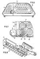
- FIG. 3 illustrates the stacked arrangement of the propellant charge modules 2 within the propellant charge magazine 13.
- the bottom 28 of the propellant charge magazine 13 is designed as an inclined plane, so that the modules 2 can be transported further into the collecting trough 18 by their own weight.
- the collecting trough 18 arranged parallel to the projectile tube axis 17 is arranged offset on the propellant charge magazine 13, so that the charging cradle 8 for receiving the propellant charge modules 2 can pivot about the axis 15 into the position 10 corresponding to the receiving trough 18.
- the charging cradles 8, 9 each contain a cranked pivot lever 29, 30, whereby the lever arm 30 of the projectile charging cradle 9 and the lever 29 of the propellant charging cradle 8 can be pivoted about the axis 15 in front of the closure opening 7.
- FIG. 4 illustrates the mounting of the propellant charging cradle 8, which can be pivoted together about the axis 15, and the projectile charging cradle 9 on the transfer arm 6.
- Each charging cradle 8, 9 contains two pivot levers 29, 30 for storage at the front and rear ends. In each case a pivot lever 29 and 30 is mounted on an axis 15 connected to the transfer arm 6.
- the projectile charging cradle 9 can be pivoted from above and the propellant charging cradle 8 from below in front of this closing opening 7, the arrangement according to FIG. 5 in each case allows the two charging cradles 8, 9 to be pivoted in exclusively from below in front of the closing opening 7.
- the pivoting lever 30.1 the projectile charging cradle 9.1 is pivotally mounted about an axis 15.1 arranged above the charging cradle 9.1 on the transfer arm 6.
- a further swivel axis 16 for receiving the propellant charge cradle 8.1 is attached to it below the storey cradle 9.1 at a distance a.
- the dimension a exceeds the swivel radius r of the projectile loading cradle 9.1 so that in an intermediate position 81 swiveled back between the transport position 11.1 and the insertion point in front of the closure opening 7, a swivel lever 29.1 smaller than the swivel arm 30.1 of the projectile loading cradle 9.1 performs the swiveling-in movement in the direction 82 in front of the closure opening 7.
- FIG. 6 illustrates the removal positions for the charging trays 8, 9 on the one hand of the propellant charge modules 2 from the propellant charge magazine 13 and on the other hand of the projectile 1 from a storey magazine 12 known per se.
- the propellant charge modules can be removed from the collecting channel 18 in the lower position 10.
- the projectile 1 can be removed from a position 11, which is not shown, above the position 10.
- FIGS. 7 and 8 illustrate the transport of the propellant charge modules 2 on the one hand into the collecting trough 18, the propellant charging modules 2 being able to be released individually from the compartments 21 by means of an actuatable pivotable locking lever 33 of an unlocking device 22 and on the other hand through one in a longitudinal slot 23 of the collecting trough 18 guided driving fingers 19 of a driving device 20 consisting of a chain hoist can be pushed together to different propellant charge lengths in the area of the receiving position 10 of the propellant charge shell 8. Any vertical The position of the propellant charge modules can be called up one after the other by unlocking devices 22 assigned to the compartments 21. In Figure 8, the propellant charge shell 8 is shown once in the receiving position 10 and once in the pivoted position 7.
Landscapes
- Engineering & Computer Science (AREA)
- General Engineering & Computer Science (AREA)
- Toys (AREA)
- Aiming, Guidance, Guns With A Light Source, Armor, Camouflage, And Targets (AREA)
Claims (6)
Applications Claiming Priority (2)
| Application Number | Priority Date | Filing Date | Title |
|---|---|---|---|
| DE3437588A DE3437588A1 (de) | 1984-10-13 | 1984-10-13 | Ladeeinrichtung fuer geschuetze |
| DE3437588 | 1984-10-13 |
Publications (2)
| Publication Number | Publication Date |
|---|---|
| EP0178484A1 EP0178484A1 (fr) | 1986-04-23 |
| EP0178484B1 true EP0178484B1 (fr) | 1988-04-06 |
Family
ID=6247817
Family Applications (1)
| Application Number | Title | Priority Date | Filing Date |
|---|---|---|---|
| EP85111886A Expired EP0178484B1 (fr) | 1984-10-13 | 1985-09-20 | Chargeur pour canons |
Country Status (3)
| Country | Link |
|---|---|
| US (1) | US4706544A (fr) |
| EP (1) | EP0178484B1 (fr) |
| DE (2) | DE3437588A1 (fr) |
Families Citing this family (24)
| Publication number | Priority date | Publication date | Assignee | Title |
|---|---|---|---|---|
| DE3627042A1 (de) * | 1986-08-09 | 1988-02-11 | Kuka Wehrtechnik Gmbh | Vorrichtung zum laden von geschuetzen, insbesondere panzerhaubitzen |
| DE3701713A1 (de) * | 1987-01-22 | 1988-08-04 | Rheinmetall Gmbh | Magazinanordnung fuer einen panzer |
| SE468610B (sv) * | 1988-09-21 | 1993-02-15 | Bofors Ab | Laddningsanordning |
| DE3931059A1 (de) * | 1989-09-18 | 1991-03-28 | Rheinmetall Gmbh | Treibladungs-portionierer fuer eine mengenvariabel beladbare ladeschale |
| DE3931192A1 (de) * | 1989-09-19 | 1991-03-28 | Rheinmetall Gmbh | Schachtmagazin fuer modulare treibladung |
| DE3932130A1 (de) * | 1989-09-27 | 1991-04-04 | Rheinmetall Gmbh | Ladevorrichtung fuer modulare treibladung |
| DE3932131A1 (de) * | 1989-09-27 | 1991-04-04 | Rheinmetall Gmbh | Entnahmewerkzeug fuer treibladungsmodule |
| SE469044B (sv) * | 1991-09-16 | 1993-05-03 | Bofors Ab | Anordning foer att vid skjutning med eldvapen minska inverkan av ett kruts temperaturberoende |
| SE508352C2 (sv) * | 1991-09-16 | 1998-09-28 | Bofors Ab | Ammunitionsenhet samt sätt för framställning av sådan |
| DE4131280A1 (de) * | 1991-09-20 | 1993-03-25 | Wegmann & Co Gmbh | Kampfpanzerturm |
| DE4134603B4 (de) * | 1991-10-19 | 2004-07-08 | Rheinmetall W & M Gmbh | Geschützturm |
| DE4205963A1 (de) * | 1992-02-27 | 1993-09-02 | Kuka Wehrtechnik Gmbh | Panzerhaubitze |
| SE503841C2 (sv) * | 1994-09-07 | 1996-09-16 | Bofors Ab | Laddsystem |
| DE19644524C2 (de) | 1996-10-26 | 2002-06-13 | Rheinmetall Landsysteme Gmbh | Geschützturm für Panzerfahrzeuge |
| SE507935C2 (sv) * | 1996-12-02 | 1998-07-27 | Bofors Ab | Sätt och anordning för frammatning av valfria granater ur fallschaktsmagasin |
| KR100388514B1 (ko) | 1998-03-04 | 2003-06-25 | 비알 비히어 비.브이. | 내연 기관용 연료 분사 장치 |
| SE519911C2 (sv) * | 2000-08-25 | 2003-04-22 | Alvis Haegglunds Ab | Vapentorn för en stridsenhet |
| SE520361C2 (sv) * | 2001-12-05 | 2003-07-01 | Alvis Haegglunds Ab | Anordning för överföring av grovkalibrig ammunition från ett ammunitionsmagasin till ett laddläge vid ett grovkalibrigt vapen |
| US6679159B1 (en) * | 2002-10-31 | 2004-01-20 | United Defense, L.P. | Ammunition transfer system |
| DE10258264A1 (de) * | 2002-12-13 | 2004-07-08 | Krauss-Maffei Wegmann Gmbh & Co. Kg | Einrichtung zum Zuführen von Treibladungen zu einer schweren Waffe |
| DE10258263B4 (de) * | 2002-12-13 | 2006-01-19 | Krauss-Maffei Wegmann Gmbh & Co. Kg | Schießmodul |
| DE102004025743A1 (de) * | 2004-05-26 | 2005-12-15 | Krauss-Maffei Wegmann Gmbh & Co. Kg | Schießmodul |
| DE102008053154A1 (de) * | 2008-10-24 | 2010-04-29 | Krauss-Maffei Wegmann Gmbh & Co. Kg | Waffensystem, insbesondere für Kampffahrzeuge |
| KR102405425B1 (ko) | 2015-12-17 | 2022-06-08 | 한화디펜스 주식회사 | 포탄 및 장약을 위한 복합장전장치 및 복합장전방법 |
Family Cites Families (5)
| Publication number | Priority date | Publication date | Assignee | Title |
|---|---|---|---|---|
| GB189815659A (en) * | 1898-07-16 | 1898-08-20 | George Sydenham Clarke | Improvements in Apparatus for facilitating the Loading of Ordnance. |
| FR754872A (fr) * | 1932-08-19 | 1933-11-15 | Schneider & Cie | Dispositif pour l'approvisionnement en munitions de deux canons associés en vue du pointage simultané en direction |
| NL43546C (fr) * | 1934-11-28 | |||
| JPS5333000A (en) * | 1976-09-09 | 1978-03-28 | Japan Steel Works Ltd:The | Automatic loading apparatus for separate type ammunition |
| US4457209A (en) * | 1980-08-27 | 1984-07-03 | Fmc Corporation | Automated large caliber ammunition handling system |
-
1984
- 1984-10-13 DE DE3437588A patent/DE3437588A1/de not_active Withdrawn
-
1985
- 1985-09-20 DE DE8585111886T patent/DE3562108D1/de not_active Expired
- 1985-09-20 EP EP85111886A patent/EP0178484B1/fr not_active Expired
- 1985-10-10 US US06/786,340 patent/US4706544A/en not_active Expired - Lifetime
Also Published As
| Publication number | Publication date |
|---|---|
| EP0178484A1 (fr) | 1986-04-23 |
| US4706544A (en) | 1987-11-17 |
| DE3562108D1 (en) | 1988-05-11 |
| DE3437588A1 (de) | 1986-04-24 |
Similar Documents
| Publication | Publication Date | Title |
|---|---|---|
| EP0178484B1 (fr) | Chargeur pour canons | |
| EP0331980B1 (fr) | Véhicule de combat, en particulier canon blindé | |
| DE3332225C2 (fr) | ||
| EP0141900B1 (fr) | Dispositif de chargement automatique pour engin blindé avec tourelle rotative blindée | |
| DE3041866C2 (de) | Vorrichtung zum Transport von Munition aus einem Munitionsbehälter zum Verschluß einer Waffe | |
| DE10258263B4 (de) | Schießmodul | |
| EP0157111A1 (fr) | Caisse à munitions pour un dispositif de chargement automatique | |
| DE3702603C2 (fr) | ||
| EP0557751B1 (fr) | Obusier blindé comportant un bras de chargement pivotant et un magasin pour munitions du type à chaîne sans fin | |
| DE3022410C2 (de) | Einrichtung zum Zuführen von Geschoßmunition in einem Panzerfahrzeug | |
| DE3642920C2 (de) | Ladevorrichtung für ein Kampffahrzeug, insbesondere eine Panzerhaubitze | |
| EP0256250B1 (fr) | Dispositif pour le chargement de canons, surtout pour canons blindés | |
| EP0277478B1 (fr) | Char de combat | |
| DE3237729C1 (de) | Vorrichtung zum Zufuehren von Geschossmunition in einem Panzerfahrzeug | |
| DE3701713C2 (fr) | ||
| DE3702426C2 (fr) | ||
| DE3722353A1 (de) | Kampffahrzeug | |
| EP0356616B1 (fr) | Chargeur pour arme en tornelle | |
| WO1986006826A1 (fr) | Dispositif de transfert de cartouches de munition d'un chargeur de bati a un chargeur de tourelle | |
| EP0635695B1 (fr) | Véhicule de combat, en particulier obusier, comportant des magasins de munitions | |
| EP0640805B1 (fr) | Dispositif d'alimentation en munitions du canon d'un char | |
| DE3733214A1 (de) | Kampfgeraet | |
| DE4134603B4 (de) | Geschützturm | |
| DE2852699C1 (de) | Einrichtung fuer die Munitionszufuhr aus einem unterhalb einer drehbaren Plattform befindlichen Magazin zu einem auf der Plattform angeordneten scheitellafettierten Geschuetz | |
| DE4126688C1 (de) | Kampffahrzeug, insbesondere Kampfpanzer, mit einem unbemannten drehbaren Turm |
Legal Events
| Date | Code | Title | Description |
|---|---|---|---|
| PUAI | Public reference made under article 153(3) epc to a published international application that has entered the european phase |
Free format text: ORIGINAL CODE: 0009012 |
|
| 17P | Request for examination filed |
Effective date: 19860215 |
|
| AK | Designated contracting states |
Kind code of ref document: A1 Designated state(s): DE GB IT |
|
| 17Q | First examination report despatched |
Effective date: 19870128 |
|
| GRAA | (expected) grant |
Free format text: ORIGINAL CODE: 0009210 |
|
| ITF | It: translation for a ep patent filed | ||
| AK | Designated contracting states |
Kind code of ref document: B1 Designated state(s): DE GB IT |
|
| GBT | Gb: translation of ep patent filed (gb section 77(6)(a)/1977) | ||
| REF | Corresponds to: |
Ref document number: 3562108 Country of ref document: DE Date of ref document: 19880511 |
|
| PLBE | No opposition filed within time limit |
Free format text: ORIGINAL CODE: 0009261 |
|
| STAA | Information on the status of an ep patent application or granted ep patent |
Free format text: STATUS: NO OPPOSITION FILED WITHIN TIME LIMIT |
|
| 26N | No opposition filed | ||
| ITTA | It: last paid annual fee | ||
| PGFP | Annual fee paid to national office [announced via postgrant information from national office to epo] |
Ref country code: GB Payment date: 19990813 Year of fee payment: 15 |
|
| PGFP | Annual fee paid to national office [announced via postgrant information from national office to epo] |
Ref country code: DE Payment date: 19990820 Year of fee payment: 15 |
|
| PG25 | Lapsed in a contracting state [announced via postgrant information from national office to epo] |
Ref country code: GB Free format text: LAPSE BECAUSE OF NON-PAYMENT OF DUE FEES Effective date: 20000920 |
|
| GBPC | Gb: european patent ceased through non-payment of renewal fee |
Effective date: 20000920 |
|
| PG25 | Lapsed in a contracting state [announced via postgrant information from national office to epo] |
Ref country code: DE Free format text: LAPSE BECAUSE OF NON-PAYMENT OF DUE FEES Effective date: 20010601 |