EP0635695B1 - Véhicule de combat, en particulier obusier, comportant des magasins de munitions - Google Patents
Véhicule de combat, en particulier obusier, comportant des magasins de munitions Download PDFInfo
- Publication number
- EP0635695B1 EP0635695B1 EP94108753A EP94108753A EP0635695B1 EP 0635695 B1 EP0635695 B1 EP 0635695B1 EP 94108753 A EP94108753 A EP 94108753A EP 94108753 A EP94108753 A EP 94108753A EP 0635695 B1 EP0635695 B1 EP 0635695B1
- Authority
- EP
- European Patent Office
- Prior art keywords
- vehicle
- magazine
- disposed
- turret
- loading
- Prior art date
- Legal status (The legal status is an assumption and is not a legal conclusion. Google has not performed a legal analysis and makes no representation as to the accuracy of the status listed.)
- Expired - Lifetime
Links
- 230000001154 acute effect Effects 0.000 claims description 2
- 239000003380 propellant Substances 0.000 description 18
- 230000033001 locomotion Effects 0.000 description 4
- 238000000034 method Methods 0.000 description 2
- 238000011161 development Methods 0.000 description 1
- 230000018109 developmental process Effects 0.000 description 1
- 230000026058 directional locomotion Effects 0.000 description 1
- 238000005192 partition Methods 0.000 description 1
- 238000002360 preparation method Methods 0.000 description 1
- 239000000725 suspension Substances 0.000 description 1
Images

Classifications
-
- F—MECHANICAL ENGINEERING; LIGHTING; HEATING; WEAPONS; BLASTING
- F41—WEAPONS
- F41A—FUNCTIONAL FEATURES OR DETAILS COMMON TO BOTH SMALLARMS AND ORDNANCE, e.g. CANNONS; MOUNTINGS FOR SMALLARMS OR ORDNANCE
- F41A9/00—Feeding or loading of ammunition; Magazines; Guiding means for the extracting of cartridges
- F41A9/01—Feeding of unbelted ammunition
- F41A9/06—Feeding of unbelted ammunition using cyclically moving conveyors, i.e. conveyors having ammunition pusher or carrier elements which are emptied or disengaged from the ammunition during the return stroke
- F41A9/09—Movable ammunition carriers or loading trays, e.g. for feeding from magazines
- F41A9/20—Movable ammunition carriers or loading trays, e.g. for feeding from magazines sliding, e.g. reciprocating
-
- F—MECHANICAL ENGINEERING; LIGHTING; HEATING; WEAPONS; BLASTING
- F41—WEAPONS
- F41A—FUNCTIONAL FEATURES OR DETAILS COMMON TO BOTH SMALLARMS AND ORDNANCE, e.g. CANNONS; MOUNTINGS FOR SMALLARMS OR ORDNANCE
- F41A9/00—Feeding or loading of ammunition; Magazines; Guiding means for the extracting of cartridges
- F41A9/82—Reloading or unloading of magazines
-
- F—MECHANICAL ENGINEERING; LIGHTING; HEATING; WEAPONS; BLASTING
- F41—WEAPONS
- F41H—ARMOUR; ARMOURED TURRETS; ARMOURED OR ARMED VEHICLES; MEANS OF ATTACK OR DEFENCE, e.g. CAMOUFLAGE, IN GENERAL
- F41H7/00—Armoured or armed vehicles
- F41H7/02—Land vehicles with enclosing armour, e.g. tanks
Definitions
- the invention relates to a combat vehicle, in particular a self-propelled howitzer, with a rotatable turret arranged on the vehicle in the area behind the center of the vehicle, on which a heavy weapon is pivotally arranged in elevation and in which at least some of the projectiles and the propellant charges are mounted inside the vehicle and a loading / unloading opening opening to the rear is arranged at the rear of the vehicle.
- Such an armored howitzer is described for example in EP 0 331 980 B1 (see the preamble of claim 1).
- the projectiles are essentially stored in the area of the center of the vehicle and are transported by means of an automatic projectile feed device from the projectile magazine with multiple rotations to the area behind the weapon end and there, with alignment in azimuth and elevation to the current direction of the weapon in the Loading position raised.
- the invention is based on the object, by means of a new concept of storing the projectiles and propellant charges within the combat vehicle, not only simplifying the process of conveying projectiles and propellant charges to the weapon, but also simplifying the loading and unloading of the vehicle with projectiles and propellant charges to reach. Furthermore, it should be achieved that the supply of projectiles and propellant charges to the weapon can be carried out by means of very simply constructed, possibly manually operated projectile supply devices.
- the invention is based on the basic idea of arranging projectiles and propellant charges as close as possible to the loading / unloading opening arranged in the rear of the vehicle, in such a way that on the one hand the available storage space within the vehicle is optimally utilized and on the other hand simple loading and unloading by means of simple mechanical aids Unloading of projectiles and propellant charges is possible.
- the ones arranged in the rear of the vehicle play transversely Bullet magazines that can be moved to the center of the vehicle and that overlap the chain boxes of the vehicle in the storage position play a preferred role.
- the space above the chain boxes can be used for storing additional storeys and / or propellant charges.
- the storage concept is supplemented by the storey magazine located in the rear of the tower. Due to this arrangement of the projectiles, the loading and unloading of the vehicle with projectiles and propellant charges as well as the transport of the projectiles from the outside or from one of the projectile magazines to the weapon can be carried out by means of very simply constructed projectile delivery devices.
- an ammunition feed device can be used, for example, for loading and unloading the vehicle and for transporting projectiles from the projectile magazines to the weapon.
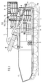
- the self-propelled howitzer shown in FIGS. 1 to 3 consists of a vehicle F with a chain undercarriage FW, on which a tower T is rotatably mounted via a slewing ring D.
- the tower T is arranged behind the center of the vehicle and on it a heavy weapon W, which is guided into the interior of the vehicle, is arranged so as to be pivotable in elevation.
- the floors are preferably stored in the rear of the vehicle and the tower.
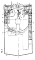
- Some of the storeys are stored in the rear of the vehicle on both sides of the longitudinal median plane M of the vehicle in a storey magazine 3 or 4, the shape of which is selected such that, as shown in FIG. 3, it is possible to store several storeys in a particularly space-saving manner .
- Each of the storey magazines 3 and 4 consists of a first part 3.1 or 4.1 which is perpendicular to the vehicle floor and a second part 3.2 or 4.2 which is arranged at the upper end of the first part and runs parallel to the vehicle floor and extends outwards.
- both Parts of storeys G3 and G4 are stored with the projectile tip pointing forward.
- Each of the two storey magazines 3 and 4 can be moved from a loading position directly in front of the loading / unloading opening B of the vehicle transversely to the longitudinal center plane M into a storage position and back (arrow direction Q1 and Q 2), as can be seen from FIGS. 2 and 3, in which the second part 3.2 or 4.2 of the storey magazine overlaps the chain case K1 or K2 running on the long sides of the vehicle interior.
- the space above the chain boxes K1 and K2 is thus optimally used in its rear part as storage space.
- the movement of the storey magazines 3 and 4 takes place via telescope guides which are connected to the vehicle and are not specifically shown and are known per se.
- the projectile magazines 3 and 4 are each held in place by locking devices, not shown.
- the longitudinal axis of the projectile magazines is offset outwards by a small acute angle ⁇ relative to the longitudinal center plane M of the vehicle.
- the projectiles are held in the storey magazines by means of simple clamping devices known per se.
- additional magazines 5 and 6 are arranged in the area in front of the storey magazines 3 and 4 above the chain boxes K1 and K2 to accommodate further storeys.
- the storeys are also arranged with the storey tip at the front. The loading and unloading of these additional magazines 5 and 6 can take place via the storey magazines 3 and 4.
- the propellant charges are also arranged inside the vehicle so that quick access is possible.
- containers 9 for receiving propellant charges are arranged on one of the chain boxes.
- Another container 7 for propellant charges is arranged in the transverse direction, seen from above on the right, next to the end of the weapon W, while an additional container 8 for propellant charges is fastened in the longitudinal direction on the inside of the right chain case K1.
- both storeys and propellant charges are also stored in the tower.
- a turret magazine 1 is arranged in the rear of the turret behind the weapon for receiving projectiles G1 which point to the front with the projectile tip and which lie one above the other in several rows.
- a further container 2 for propellant charges is arranged above and next to The tower magazine 1 for propellant charges. It has proven to be advantageous here for reasons of space saving if the propellant charges TR arranged above the storeys G1 of the tower magazine are staggered with respect to the storeys.
- the loading and unloading of the tower magazine 1 and the feeding of bullets both from the outside and from the tower magazine 1, the bullet magazines 3 and 4 and the additional magazines 5 and 6 can be carried out with the aid of a bullet feed device in the form of a loading aid, generally designated 10.
- This loading aid 10 is arranged between the rear end of the weapon W and the turret magazine 1.
- the projectile feeder is basically constructed so that a transverse guide 10.4 is attached to the inside of the roof plate of the turret T between the rear end of the weapon W and the turret magazine 1, on which a slide (arrow direction Q) is slidably guided, on which a support arm 10.1 extending downward into the tower is suspended, on which one Charging cradle receptacle is movably guided along the support arm 10.1, which carries a charging cradle 10.3.
- the arrangement and suspension of the parts is such that the longitudinal axis of the charging cradle 10.3 can be brought into a position in alignment with the barrel core axis of the weapon in at least one elevation position of the weapon W.
- the charging cradle can also be raised by means of a chain drive 10.2 on the support arm 10.1 in positions in which the rear end of the charging cradle lies directly in front of predetermined storage locations of the tower magazine 1. Furthermore, the charging cradle 10.3 can be brought into a position in which the rear end of the charging cradle directly adjoins the front end of a roller conveyor 11 arranged in the area of the loading / unloading opening B.
- the charging cradle 10.3 is pivotally connected to the charging cradle receptacle about an axis parallel to the shield pin axis of the weapon W, so that it can assume different angular positions in elevation in the different positions.
- the loading aid 10 described above can either be constructed as a simply constructed, purely manually operated unit. However, it is also possible to motorize individual movements, such as, for example, lifting the charging cradle 10.3. It has the task of relieving the operator when loading and unloading the tower magazine, when shooting from the tower magazine, when shooting from the stack and when storing the projectiles from the vehicle into the rear of the tower. With the charging cradle, which can be moved vertically on the support arm, it can still be used as a Serve preparation unit for the next floor (e.g. in the event of a fire). Furthermore, a shell-like inner charging shell part can be arranged within the charging shell in a manner not shown, which can be moved out of the charging shell in the direction of the weapon and makes it easier to attach the projectiles.
- roller conveyor 11 which can be locked in a tower-fixed holder in the region of the turret pivot bearing D. As a result, it can pivot along with the directional movements of the tower (T) within the loading / unloading opening B and remains aligned with the direction of the charging cradle 10.3.
- the roller conveyor 11 can be released from its tower holder and stowed in or on the vehicle.
- the propellant charge containers 7, 8 and 9 are preferably constructed as multi-chamber containers and are constructed in a manner not shown so that all propellant charges can be reached easily and quickly by folding down inner partition walls. This chamber design is inexpensive and the containers can be quickly replaced if necessary.
Landscapes
- Engineering & Computer Science (AREA)
- General Engineering & Computer Science (AREA)
- Aiming, Guidance, Guns With A Light Source, Armor, Camouflage, And Targets (AREA)
- Steroid Compounds (AREA)
- Saccharide Compounds (AREA)
- Medicines Containing Plant Substances (AREA)
- Emergency Lowering Means (AREA)
- Vehicle Waterproofing, Decoration, And Sanitation Devices (AREA)
- Lighters Containing Fuel (AREA)
Claims (12)
- Véhicule de combat, en particulier obusier blindé avec une tourelle disposée de manière rotative sur le véhicule, dans la zone située à l'arrière du centre de celui-ci, tourelle sur laquelle est disposée une arme lourde pouvant pivoter en élévation, dont au moins une partie des munitions et des charges propulsives sont logées à l'intérieur du véhicule, tandis qu'à l'arrière de ce véhicule est disposé un orifice de chargement/déchargement s'ouvrant vers l'arrière, caractérisé en ce qu'une partie des munitions (G3, G4) sont disposées à l'arrière du véhicule, des deux côtés du plan longitudinal central (M), respectivement dans un magasin à munitions (3, 4), lequel présente une première section (3.1, 4.1) placée perpendiculairement par rapport au fond du véhicule, ainsi qu'une deuxième section (3.2, 4.2) s'étendant vers l'extérieur, disposée parallèlement au fond du véhicule sur l'extrémité supérieure de la première section, tandis que dans la première et dans la deuxième sections sont disposées des munitions dont l'ogive est dirigée vers l'avant, et chaque magasin (3, 4) pouvant coulisser à partir d'une position de charge immédiatement devant l'orifice (B) de chargement et de déchargement du véhicule, transversalement au plan (M) de celui-ci, dans une position de stockage dans laquelle la deuxième section (3.2, 4.2) du magasin à munitions vient chevaucher les deux carters à chaînes (K1, K2) qui s'étendent chacun sur le côté longitudinal de la partie interne du véhicule.
- Véhicule de combat selon la revendication 1, caractérisé en ce que les magasins à munitions (3, 4) sont reliés au véhicule, à l'arrière de celui-ci, par des guidages télescopiques et sont bloqués tant dans la position de chargement que dans la position de stockage par des dispositifs de blocage.
- Véhicule de combat selon la revendication 1 ou 2, caractérisé en ce que l'axe longitudinal des magasins à munitions (3, 4) est légèrement décalé vers l'extérieur d'un angle aigu (α) par rapport au plan longitudinal central (M) du véhicule.
- Véhicule de combat selon l'une des revendications 1 à 3, caractérisé en ce que respectivement dans la zone située à l'avant de chaque magasin (3, 4) est disposé, au-dessus du carter à chaîne (K1, K2) du véhicule, un magasin complémentaire (5, 6) destiné à y loger d'autres munitions qui sont placées dans le sens longitudinal, leur ogive orientée vers l'avant.
- Véhicule de combat selon la revendication 4, caractérisé en ce que sur au moins l'un des carters à chaînes (K2) du véhicule est disposé, en direction longitudinale, respectivement devant le magasin complémentaire (6) des munitions, au moins un réservoir (9) destiné à recevoir des charges propulsives.
- Véhicule de combat selon l'une des revendications 1 à 5, caractérisé en ce que dans la zone adjacente à l'arme (W) est disposé dans le sens transversal, et à titre complémentaire, un autre réservoir (7) destiné à recevoir des charges propulsives.
- Véhicule de combat selon l'une des revendications 1 à 6, caractérisé en ce que sur le côté intérieur d'au moins l'un des carters à chaînes (K1) est disposé dans le sens longitudinal, un autre réservoir (8) destiné à recevoir des charges propulsives.
- Véhicule de combat selon l'une des revendications 1 à 7, caractérisé en ce qu'à l'arrière de la tourelle, derrière l'arme (W), est disposé un magasin (1) pour y loger des munitions (G1) dont l'ogive est orientée vers l'avant.
- Véhicule de combat selon la revendication 8, caractérisé en ce qu'au-dessus et/ou à côté du magasin (1) de la tourelle est disposé un autre réservoir (2) destiné à recevoir des charges propulsives.
- Véhicule de combat selon la revendication (9) caractérisé en ce que les charges propulsives disposées au-dessus des munitions (G1) du magasin (1) de la tourelle sont disposées de manière décalée par rapport à ces munitions, dans les interstices formés par celles-ci.
- Véhicule de combat selon l'une des revendications 8 à 10, caractérisé en ce que, entre l'extrémité arrière de l'arme (W) et le magasin (1) de la tourelle, est disposé un dispositif (10) d'amenée des munitions.
- Véhicule de combat selon la revendication 11, caractérisé en ce que le dispositif d'amenée des munitions présente un guidage (10.4) s'étendant en direction transversale, fixé sur le côté intérieur de la plaque de couverture de la tourelle (T), entre l'extrémité arrière de l'arme (W) et le magasin (1), guidage sur lequel coulisse un chariot, et sur ce chariot étant suspendu un bras porteur (10.1) s'étendant vers le bas à l'intérieur de la tourelle, sur ce chariot étant guidé de manière mobile le long du bras (10.1) un réceptable de la coque de chargement qui supporte une coque de chargement (10.3) de telle manière que l'axe longitudinal de cette coque peut être amené, dans au moins l'une des positions d'élévation de l'arme (W), dans une position alignée à l'axe de l'âme du canon de ladite arme, et que dans des positions dans lesquelles l'extrémité arrière de la coque (10.3) se situe immédiatement avant les emplacements déterminés du magasin de la tourelle, peut être amené dans une position dans laquelle l'extrémité arrière de la coque de chargement (10.3) fait immédiatement suite à l'extrémité arrière d'un train à rouleaux (11) disposé dans la zone de l'orifice (B) de chargement/déchargement.
Applications Claiming Priority (2)
| Application Number | Priority Date | Filing Date | Title |
|---|---|---|---|
| DE4324966A DE4324966A1 (de) | 1993-07-24 | 1993-07-24 | Kampffahrzeug, insbesondere Panzerhaubitze |
| DE4324966 | 1993-07-24 |
Publications (3)
| Publication Number | Publication Date |
|---|---|
| EP0635695A2 EP0635695A2 (fr) | 1995-01-25 |
| EP0635695A3 EP0635695A3 (fr) | 1995-05-24 |
| EP0635695B1 true EP0635695B1 (fr) | 1996-11-06 |
Family
ID=6493678
Family Applications (1)
| Application Number | Title | Priority Date | Filing Date |
|---|---|---|---|
| EP94108753A Expired - Lifetime EP0635695B1 (fr) | 1993-07-24 | 1994-06-08 | Véhicule de combat, en particulier obusier, comportant des magasins de munitions |
Country Status (4)
| Country | Link |
|---|---|
| EP (1) | EP0635695B1 (fr) |
| AT (1) | ATE145055T1 (fr) |
| DE (2) | DE4324966A1 (fr) |
| NO (1) | NO302976B1 (fr) |
Families Citing this family (3)
| Publication number | Priority date | Publication date | Assignee | Title |
|---|---|---|---|---|
| DE102011050537B3 (de) | 2011-05-20 | 2012-10-25 | Krauss-Maffei Wegmann Gmbh & Co. Kg | Geschütz und militärisches Fahrzeug |
| DE102016112322A1 (de) * | 2016-07-05 | 2018-01-11 | Krauss-Maffei Wegmann Gmbh & Co. Kg | Waffensystem |
| DE102016112323A1 (de) * | 2016-07-05 | 2018-01-11 | Krauss-Maffei Wegmann Gmbh & Co. Kg | Militärisches Fahrzeug |
Family Cites Families (2)
| Publication number | Priority date | Publication date | Assignee | Title |
|---|---|---|---|---|
| US2367837A (en) * | 1943-08-20 | 1945-01-23 | Firestone Tire & Rubber Co | Gun carrier |
| DE3807474A1 (de) * | 1988-03-08 | 1989-09-21 | Wegmann & Co | Kampffahrzeug, insbesondere panzerhaubitze |
-
1993
- 1993-07-24 DE DE4324966A patent/DE4324966A1/de not_active Withdrawn
-
1994
- 1994-06-08 EP EP94108753A patent/EP0635695B1/fr not_active Expired - Lifetime
- 1994-06-08 AT AT94108753T patent/ATE145055T1/de active
- 1994-06-08 DE DE59400986T patent/DE59400986D1/de not_active Expired - Lifetime
- 1994-06-14 NO NO942229A patent/NO302976B1/no not_active IP Right Cessation
Also Published As
| Publication number | Publication date |
|---|---|
| ATE145055T1 (de) | 1996-11-15 |
| EP0635695A3 (fr) | 1995-05-24 |
| EP0635695A2 (fr) | 1995-01-25 |
| NO942229L (no) | 1995-01-25 |
| DE59400986D1 (de) | 1996-12-12 |
| NO302976B1 (no) | 1998-05-11 |
| NO942229D0 (no) | 1994-06-14 |
| DE4324966A1 (de) | 1995-01-26 |
Similar Documents
| Publication | Publication Date | Title |
|---|---|---|
| EP1061323B1 (fr) | Véhicule blindé pour le transport de soldats | |
| EP0178484B1 (fr) | Chargeur pour canons | |
| DE2826136C3 (de) | Vorrichtung für den Munitionstransport aus einem gepanzerten Fahrzeug zu einem auf einer Plattform fest angeordneten scheitellafettierten Geschütz | |
| DE10258263B4 (de) | Schießmodul | |
| DE3017323C2 (fr) | ||
| EP0141900A1 (fr) | Dispositif de chargement automatique pour engin blindé avec tourelle rotative blindée | |
| DE3702603C2 (fr) | ||
| DE3642920C2 (de) | Ladevorrichtung für ein Kampffahrzeug, insbesondere eine Panzerhaubitze | |
| EP0042166B1 (fr) | Char comportant un système d'échange de container à munitions | |
| DE3701713C2 (fr) | ||
| EP0106074A1 (fr) | Dispositif d'alimentation en munitions dans un véhicule blindé | |
| EP0635695B1 (fr) | Véhicule de combat, en particulier obusier, comportant des magasins de munitions | |
| DE19644524C2 (de) | Geschützturm für Panzerfahrzeuge | |
| DE102004025743A1 (de) | Schießmodul | |
| DE3016928A1 (de) | Vorrichtung zum transport von munition aus einem munitionsbehaelter zur abschussvorrichtung | |
| EP0754926A2 (fr) | Tourelle pour un véhicule à roues ou à chenilles | |
| EP0221935B1 (fr) | Dispositif de transfert de cartouches de munition d'un chargeur de bati a un chargeur de tourelle | |
| DE1578069A1 (de) | Zubringvorrichtung fuer eine Abschussvorrichtung fuer fernlenkbare Flugkoerper mit Rueckstossantrieb,insbesondere zum Einbau in gepanzerte Fahrzeuge | |
| DE4123338A1 (de) | Kampfpanzerturm | |
| DE4133797C2 (de) | Kampfpanzer | |
| DE2852699C1 (de) | Einrichtung fuer die Munitionszufuhr aus einem unterhalb einer drehbaren Plattform befindlichen Magazin zu einem auf der Plattform angeordneten scheitellafettierten Geschuetz | |
| DE4134603B4 (de) | Geschützturm | |
| DE60201769T2 (de) | Automatische Munitionsladevorrichtung für eine in einem Panzerturm angeordnete Rohrwaffe | |
| DE3328208A1 (de) | Panzerturm | |
| EP0640805A1 (fr) | Dispositif d'alimentation en munitions du canon d'un char |
Legal Events
| Date | Code | Title | Description |
|---|---|---|---|
| PUAI | Public reference made under article 153(3) epc to a published international application that has entered the european phase |
Free format text: ORIGINAL CODE: 0009012 |
|
| AK | Designated contracting states |
Kind code of ref document: A2 Designated state(s): AT CH DE FR GB IT LI NL |
|
| PUAL | Search report despatched |
Free format text: ORIGINAL CODE: 0009013 |
|
| RIN1 | Information on inventor provided before grant (corrected) |
Inventor name: SCHLOEMER, HEINZ JUERGEN, DIPL.-ING. Inventor name: SCHOEPPE, OLAF Inventor name: LIEBEL, PETER Inventor name: KOHLSTEDT, MICHAEL, DIPL.-ING. Inventor name: HESSE, GUENTER, DIPL.-ING. Inventor name: WALLWEY, ERICH Inventor name: HOPKE, MANFRED Inventor name: HELDMANN, HEINRICH |
|
| AK | Designated contracting states |
Kind code of ref document: A3 Designated state(s): AT CH DE FR GB IT LI NL |
|
| RHK1 | Main classification (correction) |
Ipc: F41A 23/34 |
|
| 17P | Request for examination filed |
Effective date: 19950517 |
|
| GRAH | Despatch of communication of intention to grant a patent |
Free format text: ORIGINAL CODE: EPIDOS IGRA |
|
| 17Q | First examination report despatched |
Effective date: 19951124 |
|
| GRAH | Despatch of communication of intention to grant a patent |
Free format text: ORIGINAL CODE: EPIDOS IGRA |
|
| GRAA | (expected) grant |
Free format text: ORIGINAL CODE: 0009210 |
|
| AK | Designated contracting states |
Kind code of ref document: B1 Designated state(s): AT CH DE FR GB IT LI NL |
|
| REF | Corresponds to: |
Ref document number: 145055 Country of ref document: AT Date of ref document: 19961115 Kind code of ref document: T |
|
| REG | Reference to a national code |
Ref country code: CH Ref legal event code: NV Representative=s name: A. BRAUN, BRAUN, HERITIER, ESCHMANN AG PATENTANWAE |
|
| ITF | It: translation for a ep patent filed | ||
| GBT | Gb: translation of ep patent filed (gb section 77(6)(a)/1977) |
Effective date: 19961111 |
|
| REF | Corresponds to: |
Ref document number: 59400986 Country of ref document: DE Date of ref document: 19961212 |
|
| ET | Fr: translation filed | ||
| PLBE | No opposition filed within time limit |
Free format text: ORIGINAL CODE: 0009261 |
|
| STAA | Information on the status of an ep patent application or granted ep patent |
Free format text: STATUS: NO OPPOSITION FILED WITHIN TIME LIMIT |
|
| 26N | No opposition filed | ||
| REG | Reference to a national code |
Ref country code: GB Ref legal event code: IF02 |
|
| REG | Reference to a national code |
Ref country code: CH Ref legal event code: PFA Owner name: WEGMANN & CO. GMBH Free format text: WEGMANN & CO. GMBH#AUGUST-BODE-STRASSE 1#D-34127 KASSEL (DE) -TRANSFER TO- WEGMANN & CO. GMBH#AUGUST-BODE-STRASSE 1#D-34127 KASSEL (DE) |
|
| PGFP | Annual fee paid to national office [announced via postgrant information from national office to epo] |
Ref country code: NL Payment date: 20120628 Year of fee payment: 19 Ref country code: DE Payment date: 20120630 Year of fee payment: 19 Ref country code: CH Payment date: 20120622 Year of fee payment: 19 |
|
| PGFP | Annual fee paid to national office [announced via postgrant information from national office to epo] |
Ref country code: FR Payment date: 20120705 Year of fee payment: 19 Ref country code: GB Payment date: 20120621 Year of fee payment: 19 |
|
| PGFP | Annual fee paid to national office [announced via postgrant information from national office to epo] |
Ref country code: IT Payment date: 20120623 Year of fee payment: 19 |
|
| PGFP | Annual fee paid to national office [announced via postgrant information from national office to epo] |
Ref country code: AT Payment date: 20120620 Year of fee payment: 19 |
|
| REG | Reference to a national code |
Ref country code: NL Ref legal event code: V1 Effective date: 20140101 |
|
| REG | Reference to a national code |
Ref country code: CH Ref legal event code: PL |
|
| REG | Reference to a national code |
Ref country code: AT Ref legal event code: MM01 Ref document number: 145055 Country of ref document: AT Kind code of ref document: T Effective date: 20130608 |
|
| GBPC | Gb: european patent ceased through non-payment of renewal fee |
Effective date: 20130608 |
|
| REG | Reference to a national code |
Ref country code: FR Ref legal event code: ST Effective date: 20140228 |
|
| REG | Reference to a national code |
Ref country code: DE Ref legal event code: R119 Ref document number: 59400986 Country of ref document: DE Effective date: 20140101 |
|
| PG25 | Lapsed in a contracting state [announced via postgrant information from national office to epo] |
Ref country code: LI Free format text: LAPSE BECAUSE OF NON-PAYMENT OF DUE FEES Effective date: 20130630 Ref country code: GB Free format text: LAPSE BECAUSE OF NON-PAYMENT OF DUE FEES Effective date: 20130608 Ref country code: DE Free format text: LAPSE BECAUSE OF NON-PAYMENT OF DUE FEES Effective date: 20140101 Ref country code: NL Free format text: LAPSE BECAUSE OF NON-PAYMENT OF DUE FEES Effective date: 20140101 Ref country code: CH Free format text: LAPSE BECAUSE OF NON-PAYMENT OF DUE FEES Effective date: 20130630 |
|
| PG25 | Lapsed in a contracting state [announced via postgrant information from national office to epo] |
Ref country code: FR Free format text: LAPSE BECAUSE OF NON-PAYMENT OF DUE FEES Effective date: 20130701 Ref country code: AT Free format text: LAPSE BECAUSE OF NON-PAYMENT OF DUE FEES Effective date: 20130608 Ref country code: IT Free format text: LAPSE BECAUSE OF NON-PAYMENT OF DUE FEES Effective date: 20130608 |