EP0175166A2 - Visionneuse de film pour regarder des films négatifs en couleurs réelles - Google Patents
Visionneuse de film pour regarder des films négatifs en couleurs réelles Download PDFInfo
- Publication number
- EP0175166A2 EP0175166A2 EP19850110574 EP85110574A EP0175166A2 EP 0175166 A2 EP0175166 A2 EP 0175166A2 EP 19850110574 EP19850110574 EP 19850110574 EP 85110574 A EP85110574 A EP 85110574A EP 0175166 A2 EP0175166 A2 EP 0175166A2
- Authority
- EP
- European Patent Office
- Prior art keywords
- film
- viewing device
- support plate
- light source
- housing
- Prior art date
- Legal status (The legal status is an assumption and is not a legal conclusion. Google has not performed a legal analysis and makes no representation as to the accuracy of the status listed.)
- Withdrawn
Links
- 239000003086 colorant Substances 0.000 title 1
- 239000005338 frosted glass Substances 0.000 claims description 2
- 238000006748 scratching Methods 0.000 description 4
- 230000002393 scratching effect Effects 0.000 description 4
- 230000000295 complement effect Effects 0.000 description 3
- 239000002184 metal Substances 0.000 description 3
- 230000003287 optical effect Effects 0.000 description 3
- 239000011521 glass Substances 0.000 description 2
- 238000003780 insertion Methods 0.000 description 2
- 230000037431 insertion Effects 0.000 description 2
- 230000001681 protective effect Effects 0.000 description 2
- 230000015572 biosynthetic process Effects 0.000 description 1
- 238000006243 chemical reaction Methods 0.000 description 1
- 230000007547 defect Effects 0.000 description 1
- 230000006735 deficit Effects 0.000 description 1
- 230000000694 effects Effects 0.000 description 1
- 229910052736 halogen Inorganic materials 0.000 description 1
- 150000002367 halogens Chemical class 0.000 description 1
- 238000005286 illumination Methods 0.000 description 1
- 239000000463 material Substances 0.000 description 1
Images

Classifications
-
- H—ELECTRICITY
- H04—ELECTRIC COMMUNICATION TECHNIQUE
- H04N—PICTORIAL COMMUNICATION, e.g. TELEVISION
- H04N1/00—Scanning, transmission or reproduction of documents or the like, e.g. facsimile transmission; Details thereof
- H04N1/04—Scanning arrangements, i.e. arrangements for the displacement of active reading or reproducing elements relative to the original or reproducing medium, or vice versa
- H04N1/10—Scanning arrangements, i.e. arrangements for the displacement of active reading or reproducing elements relative to the original or reproducing medium, or vice versa using flat picture-bearing surfaces
- H04N1/1004—Scanning arrangements, i.e. arrangements for the displacement of active reading or reproducing elements relative to the original or reproducing medium, or vice versa using flat picture-bearing surfaces using two-dimensional electrical scanning, e.g. cathode-ray tubes
-
- H—ELECTRICITY
- H04—ELECTRIC COMMUNICATION TECHNIQUE
- H04N—PICTORIAL COMMUNICATION, e.g. TELEVISION
- H04N2201/00—Indexing scheme relating to scanning, transmission or reproduction of documents or the like, and to details thereof
- H04N2201/0077—Types of the still picture apparatus
-
- H—ELECTRICITY
- H04—ELECTRIC COMMUNICATION TECHNIQUE
- H04N—PICTORIAL COMMUNICATION, e.g. TELEVISION
- H04N2201/00—Indexing scheme relating to scanning, transmission or reproduction of documents or the like, and to details thereof
- H04N2201/04—Scanning arrangements
- H04N2201/0402—Arrangements not specific to a particular one of the scanning methods covered by groups H04N1/04 - H04N1/207
- H04N2201/0404—Scanning transparent media, e.g. photographic film
- H04N2201/0408—Scanning film strips or rolls
Definitions
- the present invention relates to a film viewing device for the color-correct viewing of film negatives according to the preamble of claim 1.
- a film viewing device for the color-correct viewing of film negatives is offered in photo retailers.
- the known film viewing device has a video camera, which has a built-in electronic circuit, with which the image signals, namely the brightness and color signals, are converted in such a way that the output signal is complementary to the input signal in terms of color and brightness.
- the video camera is connected to a monitor via this electronic color reversal circuit.
- An attachment lens is attached to the lens of the video camera, which in turn carries a holder over a tube into which a negative film strip can be inserted through an insertion slot.
- the holder On its side facing away from the video camera, the holder has an opening, opposite which a light source is arranged, with which the film negative can be illuminated on its side facing away from the video camera.
- the film negative strips are removed from the usual, transparent parchment laboratory bags and inserted into the guide slot of the holder for the film negative.
- This slot is made relatively narrow in order to achieve the best possible fixing of the film negative strip in the desired optical plane.
- the insertion of a film negative strip is accompanied by a relatively high mechanical load on the film negative strip, which can lead to mechanical damage to the strip by scratching.
- the holder for the film negative strip must be unlocked from the video camera by loosening a locking screw in order to view this individual image correctly, by 90 ° can be swiveled and locked again by tightening the locking screw.
- the well-known film viewing device works with a very powerful light source in order to produce a light that is as white as possible, that is to say free of color casts, for illuminating the film negative.
- the strong light source leads to an undesirably high thermal load on the negative film, which warps and bulges due to the heat from the light source.
- the curvature of the negative film strip leads to a mechanical jamming of the negative film strip in the guide slot of the holder, which in turn increases the mechanical stress on the negative film strip when the strip is pushed through for viewing different images and entails an increased risk of mechanical scratching.
- the present invention has the object to continue a film viewing device according to the preamble of claim 1 form that the handling of the film viewing device is facilitated and any risk of impairment of the negative film strips is avoided when viewing them with the film viewing device.
- the film negative strip is simply placed on the support plate. Depending on the position of the individual image of the negative film strip, this can be rotated on the support plate without having to make any complex adjustments, as is the case with the film viewing device according to the prior art.
- a surprising advantage of the design of the holder of the film viewing device according to the characterizing features of claim 1 is that the film negative strips when viewing film negatives correctly in their parchment laboratory bags or transparent laboratory bags, which can have different formats, can remain.
- the parchment-like or transparent wall of the protective cover or the photo laboratory bag has no significant influence on the quality of the image reproduced correctly with the film viewing device, so that the film negative strips can remain in their protective cover for the correct viewing of the film negatives.
- the design of the bracket of the film viewing device described in the characterizing part not only enables a change in viewing from portrait format. Pictures on landscape pictures without any conversion of any parts, but also the change between all negative formats without the need to readjust the film viewing device.
- the design of the holder reproduced in claim 2 enables the film viewing device to be used even in a bright environment, since the area between the backplate illuminated on the back and the housing opening is completely shielded from the action of laterally incident light in the lowered position of the pressure plate.
- This lowered position of the pressure plate in which it rests on the support plate or on the film negative strips lying on the support plate, is the viewing position of the film viewing device, while in the raised position of the pressure plate, a change of film negative strips or of parchment laboratory pockets that hold the film negative strips is carried out can be.
- movement of the negative film strip through a narrow slot as is customary in the prior art, is avoided.
- the only relative movement that occurs is that of raising and lowering the pressure plate with respect to the support plate, that is, a movement that is perpendicular to the image plane. With such a movement, scratching of the film negative is fundamentally excluded.
- the pressure plate In the viewing position of the pressure plate, it lies on the parchment laboratory pocket which contains the film negative strips, or lies directly on the film negative strip.
- the fixation of the film negative between the pressure plate and the support plate caused by the weight of the pressure plate causes a definite fixation of the film negative in the image plane, at the same time preventing warping or warping of the film negative strip due to any thermal effects.
- the pressure plate is fixed in its raised position with magnetic holding bodies on the housing. Even in this position, the monitor shows the negative of the film in its correct color, so that a preliminary assessment of the image and discarding completely useless motifs is possible without the pressure plate needing to be lowered. It is also possible to work in this position of the pressure plate if there is no fear of incidental light due to sufficient darkening of the surroundings, i.e. if shielding by the bellows appears unnecessary.
- the formation of the platen according to claim 5 leads to a uniform illumination of the film negative.
- color filter By arranging the color filter according to claim 6, it is possible, by simply mechanically inserting commercially available color filters in the beam path between the light source and the platen, any color defects of the To compensate for film negatives. Another considerable advantage is that the use of color filters means that a color-white, pure white light from the light source can be dispensed with. By using color filters, a color-cast light from the light source can also be used, since this can be easily compensated for by simply moving in a color filter. This enables the use of light sources with low power, which considerably reduces the thermal load on film negatives when placed on the platen. In addition, the free compensation of each color cast of the light source opens up the possibility of operating a bulb of the light source below its nominal voltage, thereby multiplying its lifespan.
- the development according to claim 7 enables the use of any video camera in the film viewing device, since the position of the camera can be adjusted with respect to the optical axis specified by the film viewing device by raising or lowering the tripod.
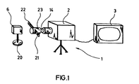
- FIG. 1 is an illustration of a known, commercially available film viewing device 1.
- a video camera 2 which is arranged on a tripod, contains an electronic circuit with which image signals from the video camera are converted into signals which are complementary in terms of color and brightness. The output signal of the electronic circuit is fed to a monitor 3, which can be designed as a commercially available color television.
- the video camera is equipped with an attachment lens 14, on which a negative film strip guide 21 is held via a tube 23.
- the negative film strip guide 21 has a guide slot running transversely to the optical axis, into which a negative film strip 22 can be inserted.
- the known film viewing device contains a light source 6 with a base 20, which is arranged such that the negative film strip 22 inserted into the negative film strip guide 21 is illuminated from the rear.
- FIG. 2 shows a cross section through a film viewing device 1 according to the present invention.
- the film viewing device 1 contains a commercially available video camera 2 and a monitor 3, which can be a commercially available color television set.
- the video camera 2 and preferably also the monitor 3 are in a housing 5 attached.
- a height-adjustable tripod 4, which carries the video camera 2 is attached to an inner wall of the housing.
- a light source 6 is attached, which may have a halogen bulb, for example.
- a plurality of color filters 7 are pivotally mounted above the light source 6, so that they can be inserted in the beam path between the light source 6 and a support plate 8 made of frosted glass located above it.
- the support plate extends in a recess in the housing up to approximately the middle of the housing, so that even relatively large transparent laboratory bags with a large number of negative film strips find space on the support plate.
- a lowerable, transparent pressure plate 9 which is preferably a conventional glass plate.
- This glass plate is connected at its periphery to the lower edge of the lower end of a bellows 10.
- the bellows is connected at its upper end to an opening 12 in the housing 5.
- the support plate 9 lies on the transparent negative film pocket 11, which in turn lies on the support plate 8.
- the wall of the housing 5 above the opening 12 is inclined at a 45 ° angle with respect to the vertical.
- a surface-vapor-coated mirror 13 is attached, which deflects the beam path from the light source 6 via the filter 7, the support plate 8, the pressure plate 9 through the interior of the bellows 10 at a 90 ° angle.
- An attachment lens 14 is attached to the standard lens of the video camera 2, which adapts the depth of field of the standard lens to the distance between the lens and the platen 8.
- the standard video camera is connected to a color signal reversing circuit 15 which is also accommodated in the housing and which is related to the
- This output signal is fed to the monitor 3, which reproduces a color-corrected, enlarged image of the film negative placed on the platen.
- FIG. 3 shows the side view of the left side of the film viewing device 1 shown in FIG. 2.
- the bellows 10 is pushed together in the illustration according to FIG. 3 and the pressure plate 9 is not in the lower position in FIG which it lies on the support plate 8, but in a raised position.
- the edge areas of the pressure plate 9 merge into metal plates 18 on both sides.
- handles 17 are provided with which the pressure plate 9 can be raised and lowered.
- Holding magnets 19 are attached to the side walls of the housing on both sides of the housing 5 in the region of the opening 12. In the raised position of the pressure plate 9, the metal plates 18 adhere to the holding magnet 19, so that the pressure plate 9 is fixed in its upper position.
- the support surface 8 can also be arranged slightly inclined, as long as the inclination of the support plate remains in such an area that a negative film strip placed on the support plate or a transparent laboratory bag placed on the support plate does not slips from this. Furthermore, it is possible to make only the small area of the platen translucent on which the individual image comes to rest when it appears on the monitor 3. The remaining areas of the support plate, which only serve as a holder for the film negative strip or the laboratory bag, can be opaque in this case made of casual material.
Landscapes
- Engineering & Computer Science (AREA)
- Multimedia (AREA)
- Signal Processing (AREA)
- Accessories Of Cameras (AREA)
Applications Claiming Priority (2)
| Application Number | Priority Date | Filing Date | Title |
|---|---|---|---|
| DE19843434238 DE3434238A1 (de) | 1984-09-18 | 1984-09-18 | Filmbetrachtungsgeraet zum farbrichtigen betrachten von filmnegativen |
| DE3434238 | 1984-09-18 |
Publications (1)
| Publication Number | Publication Date |
|---|---|
| EP0175166A2 true EP0175166A2 (fr) | 1986-03-26 |
Family
ID=6245695
Family Applications (1)
| Application Number | Title | Priority Date | Filing Date |
|---|---|---|---|
| EP19850110574 Withdrawn EP0175166A2 (fr) | 1984-09-18 | 1985-08-22 | Visionneuse de film pour regarder des films négatifs en couleurs réelles |
Country Status (2)
| Country | Link |
|---|---|
| EP (1) | EP0175166A2 (fr) |
| DE (1) | DE3434238A1 (fr) |
Cited By (2)
| Publication number | Priority date | Publication date | Assignee | Title |
|---|---|---|---|---|
| EP0343308A1 (fr) * | 1988-05-27 | 1989-11-29 | Manuel Rodriguez De Guzman Velazquez | Système et appareil de numérisation et identification de signes et/ou fac-similés |
| WO1994007325A1 (fr) * | 1992-09-12 | 1994-03-31 | Photo-Me International Plc | Ameliorations dans les installations permettant de se photographier soi-meme ou les concernant |
Families Citing this family (2)
| Publication number | Priority date | Publication date | Assignee | Title |
|---|---|---|---|---|
| US4825295A (en) * | 1985-08-09 | 1989-04-25 | Canon Kabushiki Kaisha | Image reading apparatus |
| DE9419287U1 (de) * | 1994-12-02 | 1995-03-16 | SYMICRON GmbH SOFTWARE-ENGINEERING, 40880 Ratingen | Vorrichtung zum Digitalisieren von auf einem Abschnitt eines Filmstreifens vorhandenen Bildern |
Family Cites Families (2)
| Publication number | Priority date | Publication date | Assignee | Title |
|---|---|---|---|---|
| DE2336366B2 (de) * | 1973-07-17 | 1975-10-23 | System-Service Gesellschaft Fuer Datenverarbeitung Mbh, 8000 Muenchen | Mikrofilm-Video-Aufnahmegerät und Mikrof Hm-Fe rnlese system |
| JPS5562438A (en) * | 1978-11-02 | 1980-05-10 | Olympus Optical Co Ltd | Reversal image pickup apparatus |
-
1984
- 1984-09-18 DE DE19843434238 patent/DE3434238A1/de not_active Withdrawn
-
1985
- 1985-08-22 EP EP19850110574 patent/EP0175166A2/fr not_active Withdrawn
Cited By (2)
| Publication number | Priority date | Publication date | Assignee | Title |
|---|---|---|---|---|
| EP0343308A1 (fr) * | 1988-05-27 | 1989-11-29 | Manuel Rodriguez De Guzman Velazquez | Système et appareil de numérisation et identification de signes et/ou fac-similés |
| WO1994007325A1 (fr) * | 1992-09-12 | 1994-03-31 | Photo-Me International Plc | Ameliorations dans les installations permettant de se photographier soi-meme ou les concernant |
Also Published As
| Publication number | Publication date |
|---|---|
| DE3434238A1 (de) | 1985-05-15 |
Similar Documents
| Publication | Publication Date | Title |
|---|---|---|
| DE3133546A1 (de) | "farbfernsehkamera" | |
| DE3878802T2 (de) | Konturenzeichner. | |
| EP0175166A2 (fr) | Visionneuse de film pour regarder des films négatifs en couleurs réelles | |
| DE19934619A1 (de) | Inspektionsvorrichtung für Bauteile | |
| CH670540A5 (fr) | ||
| DE8427460U1 (de) | Filmbetrachtungsgeraet zum farbrichtigen betrachten von filmnegativen | |
| DE2108721A1 (de) | Photographische Kamera | |
| DE4312654A1 (de) | Gegenlichtblende für Kameraobjektive, insbesondere von Video- und Filmkameras | |
| DE3215713C2 (de) | Einrichtung zum Abtasten einer auf einem unbeweglichen Film befindlichen Abbildung mit einer Fernsehkamera | |
| DE3904545C1 (fr) | ||
| DE4022055A1 (de) | Verfahren und vorrichtung zur farb- und helligkeitsregelung | |
| DE602005000673T2 (de) | Objektivaufsatz zur Erzeugung von Farbreflexen | |
| DE3833908C2 (fr) | ||
| DE1597218C3 (de) | Optische Anordnung in einer Farbfernsehkamera zum Ausgleich von Nachzieherscheinungen | |
| EP0053291B1 (fr) | Dispositif d'évaluation de films rayons X | |
| DE2640227A1 (de) | Vorfuehrgeraet, insbesondere audiovisuelles informationsgeraet | |
| EP0532928A1 (fr) | Appareil de communication d'images | |
| DE1228510B (de) | Kombinierte Film- und Fernsehaufnahmekamera | |
| DE102004045559B4 (de) | Filmscanner für farbige Bildvorlagen | |
| DE202008012677U1 (de) | Bildaufnahmegerät mit Aufnahmebereichs-Markierung | |
| DE617498C (de) | Schaltvorrichtung zur stoerungsfreien Formataenderung von Kinobildern | |
| CH675918A5 (fr) | ||
| DE19714444C2 (de) | Verfahren und Vorrichtung zum Belichten von fotografischem Kopiermaterial mittels einer Elektronenstrahl-Wandlerröhre | |
| DE19912254A1 (de) | Vorrichtung zur Darstellung der Bildgrenzen einer Szene | |
| DE1206161B (de) | Anordnung zur Einblendung zusaetzlicher Zeichen in Schirmbilder von Kathodenstrahl-roehren, beispielsweise in Radarschirmbilder |
Legal Events
| Date | Code | Title | Description |
|---|---|---|---|
| PUAI | Public reference made under article 153(3) epc to a published international application that has entered the european phase |
Free format text: ORIGINAL CODE: 0009012 |
|
| AK | Designated contracting states |
Kind code of ref document: A2 Designated state(s): AT BE CH FR GB IT LI NL SE |
|
| STAA | Information on the status of an ep patent application or granted ep patent |
Free format text: STATUS: THE APPLICATION HAS BEEN WITHDRAWN |
|
| 18W | Application withdrawn |
Withdrawal date: 19870402 |