EP0174831A1 - Vorrichtung und Verfahren zum Schneiden und Trennen elastischer Bänder - Google Patents
Vorrichtung und Verfahren zum Schneiden und Trennen elastischer Bänder Download PDFInfo
- Publication number
- EP0174831A1 EP0174831A1 EP85306423A EP85306423A EP0174831A1 EP 0174831 A1 EP0174831 A1 EP 0174831A1 EP 85306423 A EP85306423 A EP 85306423A EP 85306423 A EP85306423 A EP 85306423A EP 0174831 A1 EP0174831 A1 EP 0174831A1
- Authority
- EP
- European Patent Office
- Prior art keywords
- stock
- band
- movable blade
- cutting
- bands
- Prior art date
- Legal status (The legal status is an assumption and is not a legal conclusion. Google has not performed a legal analysis and makes no representation as to the accuracy of the status listed.)
- Granted
Links
Images


Classifications
-
- B—PERFORMING OPERATIONS; TRANSPORTING
- B26—HAND CUTTING TOOLS; CUTTING; SEVERING
- B26D—CUTTING; DETAILS COMMON TO MACHINES FOR PERFORATING, PUNCHING, CUTTING-OUT, STAMPING-OUT OR SEVERING
- B26D7/00—Details of apparatus for cutting, cutting-out, stamping-out, punching, perforating, or severing by means other than cutting
-
- B—PERFORMING OPERATIONS; TRANSPORTING
- B29—WORKING OF PLASTICS; WORKING OF SUBSTANCES IN A PLASTIC STATE IN GENERAL
- B29D—PRODUCING PARTICULAR ARTICLES FROM PLASTICS OR FROM SUBSTANCES IN A PLASTIC STATE
- B29D29/00—Producing belts or bands
-
- B—PERFORMING OPERATIONS; TRANSPORTING
- B26—HAND CUTTING TOOLS; CUTTING; SEVERING
- B26D—CUTTING; DETAILS COMMON TO MACHINES FOR PERFORATING, PUNCHING, CUTTING-OUT, STAMPING-OUT OR SEVERING
- B26D3/00—Cutting work characterised by the nature of the cut made; Apparatus therefor
- B26D3/16—Cutting rods or tubes transversely
- B26D3/167—Cutting tubes having a non-circular cross-section
- B26D3/168—Cutting tubes having a non-circular cross-section flattened tubes
-
- Y—GENERAL TAGGING OF NEW TECHNOLOGICAL DEVELOPMENTS; GENERAL TAGGING OF CROSS-SECTIONAL TECHNOLOGIES SPANNING OVER SEVERAL SECTIONS OF THE IPC; TECHNICAL SUBJECTS COVERED BY FORMER USPC CROSS-REFERENCE ART COLLECTIONS [XRACs] AND DIGESTS
- Y10—TECHNICAL SUBJECTS COVERED BY FORMER USPC
- Y10S—TECHNICAL SUBJECTS COVERED BY FORMER USPC CROSS-REFERENCE ART COLLECTIONS [XRACs] AND DIGESTS
- Y10S83/00—Cutting
- Y10S83/922—Tacky web cutting
-
- Y—GENERAL TAGGING OF NEW TECHNOLOGICAL DEVELOPMENTS; GENERAL TAGGING OF CROSS-SECTIONAL TECHNOLOGIES SPANNING OVER SEVERAL SECTIONS OF THE IPC; TECHNICAL SUBJECTS COVERED BY FORMER USPC CROSS-REFERENCE ART COLLECTIONS [XRACs] AND DIGESTS
- Y10—TECHNICAL SUBJECTS COVERED BY FORMER USPC
- Y10S—TECHNICAL SUBJECTS COVERED BY FORMER USPC CROSS-REFERENCE ART COLLECTIONS [XRACs] AND DIGESTS
- Y10S83/00—Cutting
- Y10S83/929—Particular nature of work or product
- Y10S83/935—Endless band
-
- Y—GENERAL TAGGING OF NEW TECHNOLOGICAL DEVELOPMENTS; GENERAL TAGGING OF CROSS-SECTIONAL TECHNOLOGIES SPANNING OVER SEVERAL SECTIONS OF THE IPC; TECHNICAL SUBJECTS COVERED BY FORMER USPC CROSS-REFERENCE ART COLLECTIONS [XRACs] AND DIGESTS
- Y10—TECHNICAL SUBJECTS COVERED BY FORMER USPC
- Y10T—TECHNICAL SUBJECTS COVERED BY FORMER US CLASSIFICATION
- Y10T225/00—Severing by tearing or breaking
- Y10T225/10—Methods
- Y10T225/12—With preliminary weakening
-
- Y—GENERAL TAGGING OF NEW TECHNOLOGICAL DEVELOPMENTS; GENERAL TAGGING OF CROSS-SECTIONAL TECHNOLOGIES SPANNING OVER SEVERAL SECTIONS OF THE IPC; TECHNICAL SUBJECTS COVERED BY FORMER USPC CROSS-REFERENCE ART COLLECTIONS [XRACs] AND DIGESTS
- Y10—TECHNICAL SUBJECTS COVERED BY FORMER USPC
- Y10T—TECHNICAL SUBJECTS COVERED BY FORMER US CLASSIFICATION
- Y10T225/00—Severing by tearing or breaking
- Y10T225/30—Breaking or tearing apparatus
- Y10T225/35—Work-parting pullers [bursters]
- Y10T225/357—Relatively movable clamps
-
- Y—GENERAL TAGGING OF NEW TECHNOLOGICAL DEVELOPMENTS; GENERAL TAGGING OF CROSS-SECTIONAL TECHNOLOGIES SPANNING OVER SEVERAL SECTIONS OF THE IPC; TECHNICAL SUBJECTS COVERED BY FORMER USPC CROSS-REFERENCE ART COLLECTIONS [XRACs] AND DIGESTS
- Y10—TECHNICAL SUBJECTS COVERED BY FORMER USPC
- Y10T—TECHNICAL SUBJECTS COVERED BY FORMER US CLASSIFICATION
- Y10T83/00—Cutting
- Y10T83/04—Processes
- Y10T83/0448—With subsequent handling [i.e., of product]
- Y10T83/0472—By moving work support to which a tacky product is adhered
-
- Y—GENERAL TAGGING OF NEW TECHNOLOGICAL DEVELOPMENTS; GENERAL TAGGING OF CROSS-SECTIONAL TECHNOLOGIES SPANNING OVER SEVERAL SECTIONS OF THE IPC; TECHNICAL SUBJECTS COVERED BY FORMER USPC CROSS-REFERENCE ART COLLECTIONS [XRACs] AND DIGESTS
- Y10—TECHNICAL SUBJECTS COVERED BY FORMER USPC
- Y10T—TECHNICAL SUBJECTS COVERED BY FORMER US CLASSIFICATION
- Y10T83/00—Cutting
- Y10T83/04—Processes
- Y10T83/0596—Cutting wall of hollow work
-
- Y—GENERAL TAGGING OF NEW TECHNOLOGICAL DEVELOPMENTS; GENERAL TAGGING OF CROSS-SECTIONAL TECHNOLOGIES SPANNING OVER SEVERAL SECTIONS OF THE IPC; TECHNICAL SUBJECTS COVERED BY FORMER USPC CROSS-REFERENCE ART COLLECTIONS [XRACs] AND DIGESTS
- Y10—TECHNICAL SUBJECTS COVERED BY FORMER USPC
- Y10T—TECHNICAL SUBJECTS COVERED BY FORMER US CLASSIFICATION
- Y10T83/00—Cutting
- Y10T83/202—With product handling means
- Y10T83/2092—Means to move, guide, or permit free fall or flight of product
- Y10T83/2198—Tiltable or withdrawable support
-
- Y—GENERAL TAGGING OF NEW TECHNOLOGICAL DEVELOPMENTS; GENERAL TAGGING OF CROSS-SECTIONAL TECHNOLOGIES SPANNING OVER SEVERAL SECTIONS OF THE IPC; TECHNICAL SUBJECTS COVERED BY FORMER USPC CROSS-REFERENCE ART COLLECTIONS [XRACs] AND DIGESTS
- Y10—TECHNICAL SUBJECTS COVERED BY FORMER USPC
- Y10T—TECHNICAL SUBJECTS COVERED BY FORMER US CLASSIFICATION
- Y10T83/00—Cutting
- Y10T83/444—Tool engages work during dwell of intermittent workfeed
- Y10T83/463—Work-feed element contacts and moves with work
- Y10T83/4632—Comprises a work-moving gripper
-
- Y—GENERAL TAGGING OF NEW TECHNOLOGICAL DEVELOPMENTS; GENERAL TAGGING OF CROSS-SECTIONAL TECHNOLOGIES SPANNING OVER SEVERAL SECTIONS OF THE IPC; TECHNICAL SUBJECTS COVERED BY FORMER USPC CROSS-REFERENCE ART COLLECTIONS [XRACs] AND DIGESTS
- Y10—TECHNICAL SUBJECTS COVERED BY FORMER USPC
- Y10T—TECHNICAL SUBJECTS COVERED BY FORMER US CLASSIFICATION
- Y10T83/00—Cutting
- Y10T83/444—Tool engages work during dwell of intermittent workfeed
- Y10T83/4645—With means to clamp work during dwell
-
- Y—GENERAL TAGGING OF NEW TECHNOLOGICAL DEVELOPMENTS; GENERAL TAGGING OF CROSS-SECTIONAL TECHNOLOGIES SPANNING OVER SEVERAL SECTIONS OF THE IPC; TECHNICAL SUBJECTS COVERED BY FORMER USPC CROSS-REFERENCE ART COLLECTIONS [XRACs] AND DIGESTS
- Y10—TECHNICAL SUBJECTS COVERED BY FORMER USPC
- Y10T—TECHNICAL SUBJECTS COVERED BY FORMER US CLASSIFICATION
- Y10T83/00—Cutting
- Y10T83/869—Means to drive or to guide tool
- Y10T83/8821—With simple rectilinear reciprocating motion only
- Y10T83/8854—Progressively cutting
Definitions
- the present invention relates, in general, to the formation of elastic bands and, more particularly, relates to the cutting of elastic bands from tubular band stock and the unbonding or separating of the sid-es-or cut edges of the bands after cutting.
- Elastic or rubber bands are formed from various combinations of synthetic and natural rubbers and filler materials.
- the fillers are used to provide the elastic bands with a variety of properties, and more particularly, they also are used to control the elasticity or elongation of the bands. Generally, as the percentage of fillers increase, the band elasticity decreases, and conversely the most elastic of the elastic bands are virtually entirely formed from synthetic or natural rubber.
- elastic bands are cut from tubular elastic band stock having a diameter equal to the desired band length in the relaxed condition. Cutting can be effected by a fly cutter, particularly for narrow widths, or a scissors-type of cutter.
- the bands are usually simply cut and then collected.
- the cutting apparatus merely deposits the bands in a jumble in a collecting bin with a random orientation.
- the cutting process also often bonds or welds the opposite sides of the bands together. This bonding is particularly common for the scissor-type of cutting apparatus.
- Such vacuum unbonding apparatus has been found to have limited effectiveness. First, it is best employed with relatively wide elastic bands. Second, the vacuum is often broken before the bond between the cut edges of the band is broken. Lastly, after separation, the bands are usually deposited in a collector in random orientations so that subsequent use of the bands requires a band sorting and orienting apparatus.
- a further object of the present invention is to provide elastic band cutting apparatus which is capable of high production and yet produces open elastic bands which may be output in a predetermined orientation onto band applying equipment.
- Still another object of the present invention is to provide an elastic band cutting and unbonding method which is fast and effective.
- Another objects of the present invention are to provide an apparatus and method for cutting and unbonding elastic bands which is durable, reliable in operation, employs a minimum number of moving parts, is easy to maintain, is economical to construct and operate and can be integrated for use with a wide range of auxilliary equipment.
- the elastic band cutting apparatus includes stock holding means, cutting means having a movable blade mounted for displacement proximate the holding means to effect cutting of the stock, and band gripping means mounted proximate the movable blade and formed to grip bands as they are cut from the stock.
- the improvement in the band cutting apparatus comprises, briefly, the gripping means including anvil means movably mounted in substantial alignment with the movable blade and biased toward the blade to grip cut bands between the blade and the anvil.
- the anvil is further displaceable by the blade in the direction of movement of the blade during cutting and preferably is laterally displaceable relative to the blade to cooperate with the blade to slide the opposite cut edges of the band longitudinally in opposite directions to break any bond occuring during cutting.
- the improved method of separating bonded.. together edges of cut elastic bands comprises, briefly, engaging opposite sides of the cut elastic band with band engaging means, and displacing the sides in opposite directions to shift the bonded edges with respect to each other to break the bonds.
- the apparatus further preferably includes band stock feeding means formed to feed stock to the stock holding means and cutting blade and operated to eject cut bands from the apparatus from separation.
- Band applying apparatus positioned proximate the cutting blade is formed to receive cut bands after separation so as to enable their use while the band orientation is still controlled.
- the elastic band cutting and separating apparatus of the present invention can be seen to include holding means 22 formed to grip and hold tubular elastic band stock 23.
- holding means 22 formed to grip and hold tubular elastic band stock 23.
- a cutting means generally designated 24, including movable blade 26 and fixed blade 27.
- the elastic band cutting apparatus of the present invention further includes gripping means, generally designated 28, mounted proximate movable blade 26 and formed to grip elastic bands as they are cut from stock 23.
- Prior art elastic band cutting apparatus particularly of the scissors-type, has included apparatus as broadly described above.
- the cutting apparatus of the present invention is formed to enable gripping and control of the elastic band after it is cut from the tubular stock and is further formed to enable breaking of the bond which typically forms between the opposed cut edges of the elastic bands so that the bands can be opened and immediately transferred to a band manipulating or applying device.
- the band cutting apparatus of the present invention is constructed so as to control the elastic band after it is cut and open it up and deposited on a band applying device so that the need for sorting and separating equipment to separate and orient the bands from a pile of randomly oriented bands is eliminated.
- the apparatus of the present invention is formed with gripping means that includes anvil means, generally designed 31, mounted to band cutting apparatus 21 in substantial alignment with movable blade 26, as best may be seen in Figure 2.
- Anvil means 31 is biased, for example, by resilient spring biasing elements 32 and 33, toward movable blade 26 to engage and grip elastic bands between the movable blade and anvil 31.
- the anvil means 31 of the apparatus of the present invention is displaceable by and in a direction of movement of blade 26, as indicated by arrows 34 and 36, while the anvil and blade grip the bands during cutting.
- the cutting apparatus of the present invention preferably includes a guillotine- shaped cutting blade 26 in which the sloped inner edge 37 that progressively shears down across cutting edge 38 of the second or fixed blade 27 so as to shear elastic bands from stock 23.
- Movable blade 26 is slidably mounted to the blade cutting apparatus by an inverted U-shaped guide plate 39 which is mounted by fasteners 41 to the apparatus and includes a blade guide channel 42 in which blade 26 slidably moves.
- Both of blades 26 and 27 are preferably formed of high strength alloy steels which will maintain the cutting edges 37 and 38 in a sharp condition which will effect shearing of the elastic band stock.
- movable blade 26 preferably includes a substantially planar surface 43 which extends parallel to the longitudinal axis of stock 23 so that surface 43 and an upwardly facing surface 44 on anvil element 46 will engage opposed sides of the elastic bands as it is sheared from stock 23.
- anvil surface 44 be positioned at about the same height or somewhat below the upper surface of second or fixed blade 27. This positioning affords immediate support for the band as it is being cut by movable blade 26 and insures ejection of cut bands, as will be described in more detail hereafter.
- the cutting apparatus of the present invention further includes a structure which will break the bonds which typically occur between the opposed edges of the bands as a result of shearing.
- a structure which will break the bonds which typically occur between the opposed edges of the bands as a result of shearing.
- the tendency of the cutting process to weld or bond adjacent edges of the band together during cutting increases.
- various portions along the length of band stock 23 are bonded together as a result of the previous cut of the tubular stock. Attempts have been made in the prior art to separate these sections or open the band up by using vacuum gripping apparatus which pull the cut band apart.
- Such apparatus is only effective if it can maintain a good vacuum with the band, which limits the use of the vacuum apparatus to bands having a substantial width dimension.
- the elastic band cutter of the present invention is intended for use in cutting bands down to and below a sixteenth of an inch in width, making use of vacuum gripping apparatus extremely difficult and relatively ineffective. Even for wide bands, the tendency is for the vacuum to break and the apparatus not to be reproducibly effective in breaking the bonds which occur.
- anvil means 31 is mounted for movement in a direction along cutting edge 37 of the movable blade.
- Such lateral movement can be accomplished by forming the anvil means as a slide plate assembly including first slide plate 46 positioned to engage the band with surface 44 and a second slide plate 47 mounted on the remote side of slide plate 46 with respect to blade 26 and stock 23.
- First slide plate 46 is pivotally mounted at 48 to the second slide plate and the second slide plate is slidably mounted to apparatus 21 by means of pins 49 which slidably pass through slots 51 in the second slide plate.
- anvil means or assembly 31 Operation of the anvil means or assembly 31 to produce a lateral displacement which will break the bonds between adjacent edges of the cut bands can best be understood by following the cutting process from the position shown in Figures 1 and 2 through the positions shown in Figures 3-6.
- movable blade 26 can be seen to have cut proximately one-half of an elastic band from stock 23.
- pneumatic or hydraulic actuator 52 has displaced piston 53, and thus cutting blade 26, downwardly until the sloped edge 37 has passed across the upper edge 38 of the fixed or second blade 27. This downward displacement urges the cut band against upper surface 44 of first anvil plate 46, which has been downwardly displaced against biasing spring 33 about pivot point 48.
- movable blade 26 has cut completely through tubular stock 23 to produce a cut band 23a.
- Pivotal anvil member 46 has pivoted about 48 to a position in which band engaging surface 44 is substantially parallel to blade surface 43 with the cut band 23a gripped between the anvil and the movable blade.
- slide plate 47 has been displaced downwardly against spring 32, with the result that the slots 51 (preferably at an acute angle with respect to the direction of motion of blade 26) and pins 49 have produced a lateral shifting of entire anvil assembly 31, as indicated by arrows 56 and 57.
- the lateral shift of the anvil assembly causes cut band 23a to have its opposite edges shifted in opposite longitudinal directions along the band.
- band 23a is, in effect, rolled along its length between the anvil and the cutting blade to thereby break any bonds which may have occurred during the shearing process on both sides of band 23a.
- band 23a is shifted to the left of stock 23, and the sliding-rolling between the anvil and the blade is highly effective in breaking any of the synthetic or natural rubber bonding produced by the shearing action of the blade.
- the lateral displacement is effected by a downward displacement of blade 26.
- the actuator 52 can be used to not only drive the blade through the band, but shift the anvil so as to cause separtion of the edges of the cut band. It is also possible, however, to drive anvil means 31 by an independent actuator, to laterally displace blade 26 by means of guide channels and/or an independent actuator or a combination of motion of the movable blade and anvil in opposite directions.
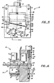
- movable blade 26 After shifting of the cut band 23a in a lateral direction to produce separation of the band edges, movable blade 26 is retracted to the position as shown in Figures 1 and 7, with the result that anvil plate 46 and 47 return to their original position with the cut band 23a separated or opened up, as shown in Figure 7, and resting on upper surface 44 of anvil and slide plate 46. Also shown in Figure 7 are a plurality of fingers 61 positioned proximate and below a surface 44 of anvil and slide plate 46.
- the elastic band stock can be axially advanced ( Figure 8) to eject cut band 23a, as indicated by arrow 62, down over fingers 61, which fingers can be a part of a band manipulating or applying apparatus that will, for example, expand the band and place it over a product or bundle of products.
- a band manipulating or applying apparatus that will, for example, expand the band and place it over a product or bundle of products.
- the cutting apparatus of the present invention controls the orientation of the bands and thus enables the elimination of sorting apparatus of the kind which would be required to extract bands from a randomly oriented- pil.e of bands.
- the elastic band cutting apparatus in the present invention further includes stock feeding means, generally designated 71, and shown in Figures 2, 4, 6, 7 and 8.
- Stock feeding means 71 is mounted proximate stock holding means 22 and is formed for periodic advancement of the elastic band stock to the holding means.
- holding means 22 can be seen to include an actuator 73 which drives a clamping plate 74 to press the stock against platform surface 76 and the upper surface of fixed blade 27.
- Feeding means 71 also preferably includes a clamping plate 77 driven by actuator 78 that will clamp stock 23 down against support surface 79, but which is shown in a raised position in Figure 2.
- a second actuator 81 with drive piston 82 is provided so that the entire feeding assembly can be displaced on guide rails 83 to provide a reciprocating carriage suitable for advancement of the stock.
- the clamping plate 77 is open and the entire assembly has been reciprocated to the left, as shown by arrow 84, so as to be in a position for clamping against the stock to advance the same.
- clamping plate 77 has been clamped down against the stock so as to grip the same.
- the stroke of actuator 81 can readily be varied so as to change the width dimension of band 23a.
- bands have been cut down to a width of 3/64 inches (1.2 millimeters). Wide bands, of course, are even easier to cut.
- the elastic band cutting method of the. present invention includes the steps of holding band stock 23, cutting an individual band 23a from the stock, releasing the stock and advancing the band to enable cutting of another band. These steps, however, are common to the prior art, and the improvement in the band cutting method of the present invention is comprised of gripping the band as it is cut between movable blade 27 and anvil means 31. Additionally, the present method includes the steps of cutting the band by shearing and displacing opposed cut edges of band 23a longitudinally in opposite directions with respect to each other to break the bonds between the edges which are caused during the shearing step. Finally, the present method includes the step of releasing and ejecting the band from between the movable blade and anvil directly onto band manipulating means 61.
Landscapes
- Engineering & Computer Science (AREA)
- Mechanical Engineering (AREA)
- Life Sciences & Earth Sciences (AREA)
- Forests & Forestry (AREA)
- Perforating, Stamping-Out Or Severing By Means Other Than Cutting (AREA)
- Control And Other Processes For Unpacking Of Materials (AREA)
- Turning (AREA)
- Nonmetal Cutting Devices (AREA)
- Processing And Handling Of Plastics And Other Materials For Molding In General (AREA)
- Details Of Cutting Devices (AREA)
Priority Applications (1)
| Application Number | Priority Date | Filing Date | Title |
|---|---|---|---|
| AT85306423T ATE59331T1 (de) | 1984-09-14 | 1985-09-10 | Vorrichtung und verfahren zum schneiden und trennen elastischer baender. |
Applications Claiming Priority (2)
| Application Number | Priority Date | Filing Date | Title |
|---|---|---|---|
| US651275 | 1984-09-14 | ||
| US06/651,275 US4579027A (en) | 1984-09-14 | 1984-09-14 | Apparatus and method for cutting and unbonding elastic bands |
Publications (2)
| Publication Number | Publication Date |
|---|---|
| EP0174831A1 true EP0174831A1 (de) | 1986-03-19 |
| EP0174831B1 EP0174831B1 (de) | 1990-12-27 |
Family
ID=24612230
Family Applications (1)
| Application Number | Title | Priority Date | Filing Date |
|---|---|---|---|
| EP85306423A Expired - Lifetime EP0174831B1 (de) | 1984-09-14 | 1985-09-10 | Vorrichtung und Verfahren zum Schneiden und Trennen elastischer Bänder |
Country Status (8)
| Country | Link |
|---|---|
| US (1) | US4579027A (de) |
| EP (1) | EP0174831B1 (de) |
| JP (1) | JPS61111900A (de) |
| KR (1) | KR860002361A (de) |
| AT (1) | ATE59331T1 (de) |
| AU (1) | AU590726B2 (de) |
| CA (1) | CA1251389A (de) |
| DE (1) | DE3581146D1 (de) |
Families Citing this family (21)
| Publication number | Priority date | Publication date | Assignee | Title |
|---|---|---|---|---|
| US5339601A (en) | 1991-05-03 | 1994-08-23 | Highland Supply Corporation | Decorative cover with band |
| US5426914A (en) | 1989-02-24 | 1995-06-27 | Highland Supply Corporation | Band applicator for applying a band about a sheet of material and a pot |
| CA1271407A (en) * | 1985-10-08 | 1990-07-10 | Kazuo Yokoe | Apparatus for severing elongate product |
| US4729305A (en) * | 1986-01-10 | 1988-03-08 | Alliance Rubber Company | Method and apparatus for making printed elastic bands |
| US5113757A (en) * | 1986-01-10 | 1992-05-19 | Alliance Rubber Company, Inc. | Method and apparatus for making printed elastic bands |
| US5165336A (en) * | 1986-01-10 | 1992-11-24 | Alliance Rubber Company, Inc. | Method and apparatus for making printed elastic bands |
| US4781093A (en) * | 1986-07-14 | 1988-11-01 | Guenard Edward F | Multi-power cutter |
| US4794832A (en) * | 1988-04-11 | 1989-01-03 | Rubber Band Technology, Ltd. | Method and apparatus for cutting and unbonding elastic bands |
| US4881868A (en) * | 1988-09-19 | 1989-11-21 | Rubber Band Technology | Apparatus and method for rapid transport of an elastic band |
| US4997337A (en) * | 1988-10-03 | 1991-03-05 | Rubber Band Technology, Ltd. | High-speed mail stacking and separating apparatus |
| JPH02110414U (de) * | 1989-02-20 | 1990-09-04 | ||
| US6311596B1 (en) * | 1990-10-05 | 2001-11-06 | Ranpak Corp. | Cutting assembly for a cushioning conversion machine |
| US5569146A (en) * | 1994-01-28 | 1996-10-29 | Ranpak Corp. | Cushioning conversion machine including a cutting/aligning assembly |
| FR2719513B1 (fr) * | 1994-05-03 | 1996-07-26 | Dal Alu Sa | Outil de coupe d'un profilé notamment une gouttière. |
| US20050034577A1 (en) * | 2003-08-14 | 2005-02-17 | Asm Assembly Automation Ltd | Apparatus and method for indexing and severing film |
| EP1730038A2 (de) * | 2004-02-10 | 2006-12-13 | Morswift Machines, Inc. | Bandiermaschine |
| CA2563247A1 (en) * | 2006-10-11 | 2008-04-11 | William Lucas | Apparatus for placing elastics on lobster claws |
| NL2004966C2 (nl) * | 2010-06-24 | 2011-12-28 | Vmi Holland Bv | Snijinrichting. |
| US9180600B2 (en) * | 2012-12-07 | 2015-11-10 | D-Cut Products, Inc. | Cutting tool |
| US10086524B2 (en) | 2012-12-07 | 2018-10-02 | D-Cut Products, Inc. | Cutting tool |
| US10434672B2 (en) | 2017-07-31 | 2019-10-08 | D-Cut Products, Inc. | Cutting tool |
Citations (3)
| Publication number | Priority date | Publication date | Assignee | Title |
|---|---|---|---|---|
| FR1254433A (fr) * | 1960-01-09 | 1961-02-24 | Joint Francais | Machine à tronçonner, notamment les boudins de caoutchouc |
| DE2030018A1 (de) * | 1969-06-20 | 1970-12-23 | ||
| DE2042817B2 (de) * | 1969-08-29 | 1979-02-15 | Moelnlycke Ab, Goeteborg (Schweden) | Vorrichtung zum Schneiden ringförmiger elastischer Bänder von einem Gummischlauch |
Family Cites Families (4)
| Publication number | Priority date | Publication date | Assignee | Title |
|---|---|---|---|---|
| US2742087A (en) * | 1954-05-25 | 1956-04-17 | Rudolph O Smith | Sheet severing equipment |
| US3410161A (en) * | 1965-10-11 | 1968-11-12 | Humston E L Co Inc | Stock feeding apparatus for punch presses and the like |
| US3842699A (en) * | 1972-07-31 | 1974-10-22 | Intermenua Pty Ltd | Shearing machines |
| US4060015A (en) * | 1973-12-29 | 1977-11-29 | Chajim Gros | Apparatus and method for manufacturing resilient bands |
-
1984
- 1984-09-14 US US06/651,275 patent/US4579027A/en not_active Expired - Fee Related
-
1985
- 1985-09-10 EP EP85306423A patent/EP0174831B1/de not_active Expired - Lifetime
- 1985-09-10 AT AT85306423T patent/ATE59331T1/de not_active IP Right Cessation
- 1985-09-10 DE DE8585306423T patent/DE3581146D1/de not_active Expired - Fee Related
- 1985-09-13 KR KR1019850006692A patent/KR860002361A/ko not_active Application Discontinuation
- 1985-09-13 AU AU47462/85A patent/AU590726B2/en not_active Ceased
- 1985-09-14 JP JP60204168A patent/JPS61111900A/ja active Pending
- 1985-09-16 CA CA000490810A patent/CA1251389A/en not_active Expired
Patent Citations (3)
| Publication number | Priority date | Publication date | Assignee | Title |
|---|---|---|---|---|
| FR1254433A (fr) * | 1960-01-09 | 1961-02-24 | Joint Francais | Machine à tronçonner, notamment les boudins de caoutchouc |
| DE2030018A1 (de) * | 1969-06-20 | 1970-12-23 | ||
| DE2042817B2 (de) * | 1969-08-29 | 1979-02-15 | Moelnlycke Ab, Goeteborg (Schweden) | Vorrichtung zum Schneiden ringförmiger elastischer Bänder von einem Gummischlauch |
Also Published As
| Publication number | Publication date |
|---|---|
| AU590726B2 (en) | 1989-11-16 |
| CA1251389A (en) | 1989-03-21 |
| ATE59331T1 (de) | 1991-01-15 |
| KR860002361A (ko) | 1986-04-24 |
| US4579027A (en) | 1986-04-01 |
| DE3581146D1 (de) | 1991-02-07 |
| EP0174831B1 (de) | 1990-12-27 |
| AU4746285A (en) | 1986-03-20 |
| JPS61111900A (ja) | 1986-05-29 |
Similar Documents
| Publication | Publication Date | Title |
|---|---|---|
| US4579027A (en) | Apparatus and method for cutting and unbonding elastic bands | |
| US5195413A (en) | Shearing tool for punch presses | |
| US3867754A (en) | Stripper crimper machine | |
| US4404742A (en) | Method and apparatus for mounting rivets or the like in a flexible carrier | |
| EP0059940B1 (de) | Verfahren und Vorrichtung zum Abschneiden der verschlossenen Enden von Verpackungshüllen | |
| US4333300A (en) | Envelope processing machine and method | |
| US3903934A (en) | Collapsible forming die | |
| EP0391747B1 (de) | Einschneidiger Stanzblock | |
| EP1680263A2 (de) | Verfahren und vorrichtung zum aufschneiden von lebensmittelriegeln | |
| EP1264792B1 (de) | Vorrichtung and Verfahren zur Unterteilung eines Stapels von Blättern in Riese vorgegebener Blattzahl | |
| DE1057192B (de) | Maschine zum Abisolieren des Endes eines isolierten Drahtes und zum Anbringen eines elektrischen Verbinders auf diesem Drahtende | |
| EP1995026B1 (de) | Verfahren zum Aufschneiden von Lebensmittelriegeln | |
| EP0144003A2 (de) | Vorrichtung zur Erzeugung von Kantholz durch spanloses Abtrennen von Seitenbrettern | |
| JPS585160B2 (ja) | オシヌキソウチ | |
| DE2244144C3 (de) | Vorrichtung zum Abschneiden von Scheiben von einem Materialblock | |
| US4794832A (en) | Method and apparatus for cutting and unbonding elastic bands | |
| DE2014494C3 (de) | Verfahren und Maschine zum Andrücken U-förmiger Zwingen an Leiterenden | |
| JP3159462B2 (ja) | プレス式走行パイプ切断機 | |
| EP0699395A2 (de) | Vorrichtung zum Abtrennen von Scheiben von Ballen | |
| JP2602482B2 (ja) | 端子テ−プ移動手段を改良した電気端子アプリケ−タ | |
| EP0123117A1 (de) | Verfahren und Vorrichtung zur Herstellung von verstellbaren Trägern | |
| US3677116A (en) | Blanking device for ribbon cable | |
| US4077185A (en) | Apparatus for manufacturing and wrapping labels | |
| DE2142703C3 (de) | Vorrichtung zum Erzeugen keilförmiger Enden an zum Herstellen von Kettengliedern dienenden Stababschnitten | |
| CN212795256U (zh) | 一种刮水器连接杆冲断装置 |
Legal Events
| Date | Code | Title | Description |
|---|---|---|---|
| PUAI | Public reference made under article 153(3) epc to a published international application that has entered the european phase |
Free format text: ORIGINAL CODE: 0009012 |
|
| AK | Designated contracting states |
Kind code of ref document: A1 Designated state(s): AT BE CH DE FR GB IT LI LU NL SE |
|
| 17P | Request for examination filed |
Effective date: 19860910 |
|
| 17Q | First examination report despatched |
Effective date: 19870721 |
|
| RAP1 | Party data changed (applicant data changed or rights of an application transferred) |
Owner name: RUBBER BAND TECHNOLOGY, LTD., |
|
| GRAA | (expected) grant |
Free format text: ORIGINAL CODE: 0009210 |
|
| AK | Designated contracting states |
Kind code of ref document: B1 Designated state(s): AT BE CH DE FR GB IT LI LU NL SE |
|
| PG25 | Lapsed in a contracting state [announced via postgrant information from national office to epo] |
Ref country code: NL Effective date: 19901227 Ref country code: LI Effective date: 19901227 Ref country code: IT Free format text: LAPSE BECAUSE OF FAILURE TO SUBMIT A TRANSLATION OF THE DESCRIPTION OR TO PAY THE FEE WITHIN THE PRESCRIBED TIME-LIMIT;WARNING: LAPSES OF ITALIAN PATENTS WITH EFFECTIVE DATE BEFORE 2007 MAY HAVE OCCURRED AT ANY TIME BEFORE 2007. THE CORRECT EFFECTIVE DATE MAY BE DIFFERENT FROM THE ONE RECORDED. Effective date: 19901227 Ref country code: CH Effective date: 19901227 Ref country code: BE Effective date: 19901227 Ref country code: AT Effective date: 19901227 |
|
| REF | Corresponds to: |
Ref document number: 59331 Country of ref document: AT Date of ref document: 19910115 Kind code of ref document: T |
|
| REF | Corresponds to: |
Ref document number: 3581146 Country of ref document: DE Date of ref document: 19910207 |
|
| ET | Fr: translation filed | ||
| REG | Reference to a national code |
Ref country code: CH Ref legal event code: PL |
|
| NLV1 | Nl: lapsed or annulled due to failure to fulfill the requirements of art. 29p and 29m of the patents act | ||
| PGFP | Annual fee paid to national office [announced via postgrant information from national office to epo] |
Ref country code: SE Payment date: 19910802 Year of fee payment: 7 |
|
| PGFP | Annual fee paid to national office [announced via postgrant information from national office to epo] |
Ref country code: GB Payment date: 19910823 Year of fee payment: 7 |
|
| PGFP | Annual fee paid to national office [announced via postgrant information from national office to epo] |
Ref country code: DE Payment date: 19910918 Year of fee payment: 7 |
|
| PG25 | Lapsed in a contracting state [announced via postgrant information from national office to epo] |
Ref country code: LU Free format text: LAPSE BECAUSE OF NON-PAYMENT OF DUE FEES Effective date: 19910930 |
|
| PLBE | No opposition filed within time limit |
Free format text: ORIGINAL CODE: 0009261 |
|
| STAA | Information on the status of an ep patent application or granted ep patent |
Free format text: STATUS: NO OPPOSITION FILED WITHIN TIME LIMIT |
|
| 26N | No opposition filed | ||
| PGFP | Annual fee paid to national office [announced via postgrant information from national office to epo] |
Ref country code: FR Payment date: 19920129 Year of fee payment: 7 |
|
| PG25 | Lapsed in a contracting state [announced via postgrant information from national office to epo] |
Ref country code: GB Effective date: 19920910 |
|
| PG25 | Lapsed in a contracting state [announced via postgrant information from national office to epo] |
Ref country code: SE Effective date: 19920911 |
|
| GBPC | Gb: european patent ceased through non-payment of renewal fee |
Effective date: 19920910 |
|
| PG25 | Lapsed in a contracting state [announced via postgrant information from national office to epo] |
Ref country code: FR Effective date: 19930528 |
|
| PG25 | Lapsed in a contracting state [announced via postgrant information from national office to epo] |
Ref country code: DE Effective date: 19930602 |
|
| REG | Reference to a national code |
Ref country code: FR Ref legal event code: ST |
|
| EUG | Se: european patent has lapsed |
Ref document number: 85306423.6 Effective date: 19930406 |