EP0172272B1 - Control system for three way variable shock absorber device for suspension with highest shock absorber effectiveness not selected in manual mode - Google Patents
Control system for three way variable shock absorber device for suspension with highest shock absorber effectiveness not selected in manual mode Download PDFInfo
- Publication number
- EP0172272B1 EP0172272B1 EP84115867A EP84115867A EP0172272B1 EP 0172272 B1 EP0172272 B1 EP 0172272B1 EP 84115867 A EP84115867 A EP 84115867A EP 84115867 A EP84115867 A EP 84115867A EP 0172272 B1 EP0172272 B1 EP 0172272B1
- Authority
- EP
- European Patent Office
- Prior art keywords
- vehicle
- condition
- selecting
- shock absorber
- mode
- Prior art date
- Legal status (The legal status is an assumption and is not a legal conclusion. Google has not performed a legal analysis and makes no representation as to the accuracy of the status listed.)
- Expired
Links
- 230000035939 shock Effects 0.000 title claims description 167
- 239000006096 absorbing agent Substances 0.000 title claims description 166
- 239000000725 suspension Substances 0.000 title claims description 37
- 238000013016 damping Methods 0.000 claims description 140
- 230000005540 biological transmission Effects 0.000 claims description 18
- 230000000694 effects Effects 0.000 claims description 7
- 230000009189 diving Effects 0.000 claims description 3
- 238000012360 testing method Methods 0.000 description 44
- 230000003247 decreasing effect Effects 0.000 description 27
- 230000001133 acceleration Effects 0.000 description 19
- 230000000670 limiting effect Effects 0.000 description 17
- 230000007935 neutral effect Effects 0.000 description 9
- 230000036461 convulsion Effects 0.000 description 5
- 230000006870 function Effects 0.000 description 5
- 230000002939 deleterious effect Effects 0.000 description 4
- 230000000977 initiatory effect Effects 0.000 description 4
- 230000002265 prevention Effects 0.000 description 4
- 238000010586 diagram Methods 0.000 description 3
- 238000000034 method Methods 0.000 description 3
- 230000008569 process Effects 0.000 description 3
- HCBIBCJNVBAKAB-UHFFFAOYSA-N Procaine hydrochloride Chemical compound Cl.CCN(CC)CCOC(=O)C1=CC=C(N)C=C1 HCBIBCJNVBAKAB-UHFFFAOYSA-N 0.000 description 2
- 230000009471 action Effects 0.000 description 2
- 230000008859 change Effects 0.000 description 2
- 238000006243 chemical reaction Methods 0.000 description 2
- 238000010276 construction Methods 0.000 description 2
- 230000010485 coping Effects 0.000 description 2
- 230000006866 deterioration Effects 0.000 description 2
- 238000007689 inspection Methods 0.000 description 2
- 230000007704 transition Effects 0.000 description 2
- PUAQLLVFLMYYJJ-UHFFFAOYSA-N 2-aminopropiophenone Chemical compound CC(N)C(=O)C1=CC=CC=C1 PUAQLLVFLMYYJJ-UHFFFAOYSA-N 0.000 description 1
- 230000004075 alteration Effects 0.000 description 1
- 238000002485 combustion reaction Methods 0.000 description 1
- 230000001419 dependent effect Effects 0.000 description 1
- 230000000994 depressogenic effect Effects 0.000 description 1
- 238000002474 experimental method Methods 0.000 description 1
- 238000012986 modification Methods 0.000 description 1
- 230000004048 modification Effects 0.000 description 1
- 238000002360 preparation method Methods 0.000 description 1
- 238000012545 processing Methods 0.000 description 1
- 238000005096 rolling process Methods 0.000 description 1
Images

Classifications
-
- B—PERFORMING OPERATIONS; TRANSPORTING
- B60—VEHICLES IN GENERAL
- B60G—VEHICLE SUSPENSION ARRANGEMENTS
- B60G17/00—Resilient suspensions having means for adjusting the spring or vibration-damper characteristics, for regulating the distance between a supporting surface and a sprung part of vehicle or for locking suspension during use to meet varying vehicular or surface conditions, e.g. due to speed or load
- B60G17/06—Characteristics of dampers, e.g. mechanical dampers
- B60G17/08—Characteristics of fluid dampers
-
- B—PERFORMING OPERATIONS; TRANSPORTING
- B60—VEHICLES IN GENERAL
- B60G—VEHICLE SUSPENSION ARRANGEMENTS
- B60G17/00—Resilient suspensions having means for adjusting the spring or vibration-damper characteristics, for regulating the distance between a supporting surface and a sprung part of vehicle or for locking suspension during use to meet varying vehicular or surface conditions, e.g. due to speed or load
- B60G17/015—Resilient suspensions having means for adjusting the spring or vibration-damper characteristics, for regulating the distance between a supporting surface and a sprung part of vehicle or for locking suspension during use to meet varying vehicular or surface conditions, e.g. due to speed or load the regulating means comprising electric or electronic elements
- B60G17/016—Resilient suspensions having means for adjusting the spring or vibration-damper characteristics, for regulating the distance between a supporting surface and a sprung part of vehicle or for locking suspension during use to meet varying vehicular or surface conditions, e.g. due to speed or load the regulating means comprising electric or electronic elements characterised by their responsiveness, when the vehicle is travelling, to specific motion, a specific condition, or driver input
-
- B—PERFORMING OPERATIONS; TRANSPORTING
- B60—VEHICLES IN GENERAL
- B60G—VEHICLE SUSPENSION ARRANGEMENTS
- B60G2400/00—Indexing codes relating to detected, measured or calculated conditions or factors
- B60G2400/10—Acceleration; Deceleration
- B60G2400/106—Acceleration; Deceleration longitudinal with regard to vehicle, e.g. braking
-
- B—PERFORMING OPERATIONS; TRANSPORTING
- B60—VEHICLES IN GENERAL
- B60G—VEHICLE SUSPENSION ARRANGEMENTS
- B60G2400/00—Indexing codes relating to detected, measured or calculated conditions or factors
- B60G2400/20—Speed
- B60G2400/204—Vehicle speed
-
- B—PERFORMING OPERATIONS; TRANSPORTING
- B60—VEHICLES IN GENERAL
- B60G—VEHICLE SUSPENSION ARRANGEMENTS
- B60G2400/00—Indexing codes relating to detected, measured or calculated conditions or factors
- B60G2400/30—Propulsion unit conditions
- B60G2400/302—Selected gear ratio; Transmission function
-
- B—PERFORMING OPERATIONS; TRANSPORTING
- B60—VEHICLES IN GENERAL
- B60G—VEHICLE SUSPENSION ARRANGEMENTS
- B60G2400/00—Indexing codes relating to detected, measured or calculated conditions or factors
- B60G2400/30—Propulsion unit conditions
- B60G2400/33—Throttle position
-
- B—PERFORMING OPERATIONS; TRANSPORTING
- B60—VEHICLES IN GENERAL
- B60G—VEHICLE SUSPENSION ARRANGEMENTS
- B60G2400/00—Indexing codes relating to detected, measured or calculated conditions or factors
- B60G2400/40—Steering conditions
- B60G2400/41—Steering angle
-
- B—PERFORMING OPERATIONS; TRANSPORTING
- B60—VEHICLES IN GENERAL
- B60G—VEHICLE SUSPENSION ARRANGEMENTS
- B60G2500/00—Indexing codes relating to the regulated action or device
- B60G2500/10—Damping action or damper
- B60G2500/102—Damping action or damper stepwise
-
- B—PERFORMING OPERATIONS; TRANSPORTING
- B60—VEHICLES IN GENERAL
- B60G—VEHICLE SUSPENSION ARRANGEMENTS
- B60G2600/00—Indexing codes relating to particular elements, systems or processes used on suspension systems or suspension control systems
- B60G2600/02—Retarders, delaying means, dead zones, threshold values, cut-off frequency, timer interruption
-
- B—PERFORMING OPERATIONS; TRANSPORTING
- B60—VEHICLES IN GENERAL
- B60G—VEHICLE SUSPENSION ARRANGEMENTS
- B60G2600/00—Indexing codes relating to particular elements, systems or processes used on suspension systems or suspension control systems
- B60G2600/18—Automatic control means
-
- B—PERFORMING OPERATIONS; TRANSPORTING
- B60—VEHICLES IN GENERAL
- B60G—VEHICLE SUSPENSION ARRANGEMENTS
- B60G2600/00—Indexing codes relating to particular elements, systems or processes used on suspension systems or suspension control systems
- B60G2600/20—Manual control or setting means
-
- B—PERFORMING OPERATIONS; TRANSPORTING
- B60—VEHICLES IN GENERAL
- B60G—VEHICLE SUSPENSION ARRANGEMENTS
- B60G2800/00—Indexing codes relating to the type of movement or to the condition of the vehicle and to the end result to be achieved by the control action
- B60G2800/01—Attitude or posture control
- B60G2800/012—Rolling condition
-
- B—PERFORMING OPERATIONS; TRANSPORTING
- B60—VEHICLES IN GENERAL
- B60G—VEHICLE SUSPENSION ARRANGEMENTS
- B60G2800/00—Indexing codes relating to the type of movement or to the condition of the vehicle and to the end result to be achieved by the control action
- B60G2800/01—Attitude or posture control
- B60G2800/014—Pitch; Nose dive
-
- B—PERFORMING OPERATIONS; TRANSPORTING
- B60—VEHICLES IN GENERAL
- B60G—VEHICLE SUSPENSION ARRANGEMENTS
- B60G2800/00—Indexing codes relating to the type of movement or to the condition of the vehicle and to the end result to be achieved by the control action
- B60G2800/22—Braking, stopping
Definitions
- the present invention relates to a control system for a shock absorber device used in a suspension of an automobile, and more particularly relates to a suspension control system as disclosed by GB-A-2 119 473 and specified in the first part of independent claim 1.
- the suspension of a vehicle typically incorporates at least one, and usually a plurality, of shock absorber devices, in order to provide damping action for the movement of the vehicle body with respect to the wheels thereof.
- the amount of damping effect of such a shock absorber is preferred to be relatively low in order to provide good and comfortable vehicle ridability, but paradoxically is preferred to be relatively high in order to provide good and stable vehicle steering characteristics and turning characteristics such as anti roll, as well as good acceleration and braking characteristics such as anti squat and anti dive and anti starting squat and anti starting tail lift.
- shock absorber devices which have variable damping effectiveness.
- a control system therefor which controls the damping effectiveness of said shock absorber, and varies it in accordance with various parameters of the vehicle relating to its operational conditions.
- Such a shock absorber device is typically adjustable with regard to its damping effectiveness either to two discrete conditions, a first condition in which it provides a lower value of damping effectiveness and a second condition in which it provides a higher value of damping effectiveness, or to three discrete conditions, a first condition in which it provides a minimum value of damping effectiveness, a second condition in which it provides a medium value of damping effectiveness, or a third condition in which it provides a maximum value of damping effectiveness.
- the action is typically such that, either manually according to the preference of the vehicle operator or automatically according to the operational conditions of the vehicle, the shock absorber device is switched between its various conditions to provide varying damping effectiveness.
- shock absorber device control system in the 1983 model Toyota Soarer GT automobile which is manufactured by the applicant of the Japanese Patent Application of which priority is being claimed in this present patent application, can be manually set by the vehicle operator operating a mode select switch provided within the passenger compartment to any one of a "normal mode", a "sport mode”, and an "auto mode".
- the damping effectiveness of the shock absorber devices of the suspension of the vehicle are set to be constant at a relatively small value; in the "sport mode” said damping effectiveness of said shock absorber devices are set to be constant at a relatively large value; and in the “auto mode” said damping effectiveness of said shock absorber devices are switched between said relatively small value and said relatively large value according to signals output from various detecting means such as sensors and switches which detect operational parameters of the vehicle.
- EP-A-0 106 697 shows a suspension control system for a variable damping effectiveness type shock absorber comprising a changeover switch adapted to be selectively operated to enable automatic and manual control respectively.
- the magnitude of the damping force is changed in two stages including a high and a low level. It can also be changed in a continuous manner by continuously changing the cross-sectional areas of an orifice and communiction apertures within the damper unit.
- said actuator for said shock absorber device is only set to its first condition or its second condition, and is never set to its said third condition; and accordingly the shock absorber device is prevented, during manual system operation, from being set to its hardest setting in which it provides its greatest value of damping effectiveness.
- shock absorber device since the hardest setting of said shock absorber device is not available in manual mode, it is prevented that, due to improper or injudicious manual actuation of the system by the vehicle driver, the shock absorber device should be set to an over high damping effectiveness which is harder than necessary, and that due to such improper manual operation by the driver the vehicle ridability should be deteriorated.
- said actuator for said shock absorber device can be set, according to vehicle operational conditions, either to its said first condition, to its said second condition, or to its said third condition; and accordingly the shock absorber device is, during automatic system operation, allowed to be set to its hardest setting in which it provides its greatest value of damping effectiveness, so that the full operational potential of the shock absorber device is allowed to be realized during automatic system operation.
- a suspension control system as described above, wherein said selecting means, when thus selecting said auto operational mode, is for further selecting according to said manual control by the operator between a first auto operational mode and a second auto operational mode; wherein said control means, when said manually controlled selecting means is thus selecting said first auto operational mode, is for actuating said actuator to either its said first condition or its said third condition according to said information signals representing the operational condition of the vehicle outputted by said detecting means; and wherein further said control means, when said manually controlled selecting means is thus selecting said second auto operational mode, is for actuating said actuator to either its said second condition or its said third condition accordinging to said information signals representing the operational condition of the vehicle outputted by said detecting means.
- the vehicle operator can select at will between an automatic operational mode in which the shock absorber device damping effectiveness is switched between a minimum value and a maximum value, and another automatic operational mode in which the shock absorber device damping effectiveness is switched between a medium value and said maximum value.
- the suspension characteristics of the vehicle may be adjusted by the driver, even in the automatic mode, according to his or her particular taste.
- a suspension control system as described above, wherein said detecting means comprises a vehicle speed sensor which outputs a signal representative of vehicle road speed, and wherein said control means is for, when said vehicle speed sensor is outputting to it a signal indicating a vehicle speed of at least a determined speed value, and said manually controlled selecting means is selecting said auto operational mode, actuating said actuator to one or the other of its said second condition and its said third condition, according to other information signals outputted by said detecting means.
- the vehicle steering stability during high speed operation is improved, while maintaining good vehicle ridability, especially if, as is also preferable, when said vehicle speed sensor is outputting a signal indicating a vehicle speed of below said determinate speed value, and said manually controlled selecting means is selecting said auto operational mode, said actuator is actuated to one or the other of its said first condition and its said third condition.
- said detecting means may comprise a vehicle speed sensor which outputs a signal representative of vehicle road speed and a vehicle steering angle sensor which outputs a signal representative of turning angle of a steering system of the vehicle, and in this case said control means should be for, when said vehicle speed sensor and said vehicle steering angle sensor are outputting to it signals indicating a combination of vehicle speed and vehicle steering angle which is liable to cause body roll, and said manually controlled selecting means is selecting said auto operational mode, actuating said actuator to its said third condition.
- This sytem can reduce vehicle body roll while cornering.
- said detecting means may comprise a vehicle throttle sensor which outputs a signal representative of vehicle engine load, and in this case said control means should be for, when said vehicle throttle sensor is outputting to it a signal indicating a vehicle powering condition which is liable to cause vehicle body squat, and' said manually controlled selecting means is selecting said auto operational mode, actuating said actuator to its said third condition.
- This sytem can reduce vehicle squat while accelerating.
- said detecting means may comprise a vehicle braking sensor which outputs a signal representative of vehicle braking situation, and in this case said control means should be for, when said vehicle braking sensor is outputting to it a signal indicating a vehicle braking condition which is liable to cause vehicle body nose diving, and said manually controlled selecting means is selecting said auto operational mode, actuating said actuator to its said third condition.
- This system can reduce vehicle nose dive while braking.
- said detecting means may comprise a vehicle transmission sensor which outputs a signal representative of vehicle transmission driving capability, and in this case said control means should be for, when said vehicle transmission sensor is outputting to it a signal indicating a vehicle transmission driving capability condition which is liable to cause vehicle starting squat or tail lift, and said manually controlled selecting means is selecting said auto operational mode, actuating said actuator to its said third condition.
- This system can reduce vehicle starting squat and starting tail lift.
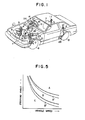
- FIG. 1 is a diagrammatical perspective view of an automobile equipped with an automatic transmission and with a suspension control system including four shock absorber devices, which are designated by the reference numerals 1
- the shock absorber device 1 is for the suspension system for the right front wheel 5 of the vehicle
- the shock absorber device 2 is for the suspension system for the left front wheel 6
- the shock absorber device 3 is for the suspension system for the rear right wheel 7
- the shock absorber device 4 is for the suspension system for the left rear wheel 8.
- each of these shock absorber devices 1 through 4 is controlled with regard to its damping effectiveness by an example of the preferred embodiment of the damping effectiveness control sytem according to the present invention, said four examples of said preferred embodiment in fact sharing some common structural elements.
- each of the absorber devices 1, 2, 3, and 4 is equipped with an electrically driven actuator 9, 10, 11 and 12 respectively, and, although this is not particularly shown in the drawings, each of these actuators according to selective electrical control thereof controls the flow resistance of an orifice means provided in its corresponding shock absorber device to have one of three different values, i.e. to be either at a maximum value, or a medium value, or a minimum value; so that the respective shock absorber device exhibits a maximum damping effectiveness, or a medium damping effectiveness, or a minimum damping effectiveness, respectively.
- the details of the construction provided for the shock absorber devices 1 through 4 and for the acuators 9 through 12 and the orifice means controlled thereby and so on are not particularly shown, because such variable damping effectiveness type shock absorbers are per se known in various forms.
- a vehicle speed sensor 14 which is built. into a speedometer provided in said instrument panel.
- This vehicle speed sensor 14 detects the speed of the vehicle along the road, and outputs an electrical signal indicative thereof.
- a steering sensor 17 which detects the angle through which the steering wheel 16 and the steering column 15 have turned, either way, from their straight ahead positions, and which outputs an electrical signal representative thereof; this signal accordingly is representative of the angle through which the front wheels 5 and 6 of the vehicle have turned, either way, from their straight ahead positions.
- a carburetor fitted to the internal combustion engine 18 of the vehicle has a throttle body to which a throttle position sensor 19 is fitted, and this throttle position sensor 19 detects the amount of opening of a throttle valve provided within the throttle body and outputs an electrical signal representative thereof, i.e. representative of the current load on the engine of the vehicle.
- a stop lamp switch 20 which acts as a brake sensor, and is closed when and only when the brake pedal is depressed, thus outputting an electrical resistance signal representative of whether the vehicle is being braked or not.
- a neutral start switch 23 which acts as a shift position sensor, and which is closed when the shift lever 22 is set to the N (neutral) position or to the P (park) position, and is otherwise open.
- this neutral start switch 23 outputs an electrical reistance signal representative of whether the transmission 21 is currently driving the vehicle, or not.
- this mode seleot switch unit 24 for the driver of the vehicle to use for manually selecting the control mode for the damping effectiveness control system for the shock absorber devices 1 through 4, as will be explained later:
- this mode seleot switch unit 24, in this preferred embodiment of the present invention, comprises a first mode select switch 25 and a second mode select switch 26.
- an indicator 27 for indicating to the driver of the vehicle the control mode for the damping effectiveness control system for the shock absorber devices 1 through 4 currently selected by the operation of the mode select switch unit 24, as well as the current magnitude of the damping effectiveness being provided by the shock absorber devices 1 through 4.
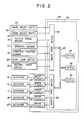
- Fig. 2 there is shown a block diagram of the suspension control system and the preferred embodiment of the damping effectiveness control system according to the present invention, which incorporates an electronic control device 28.
- the electrical output signals from all the various sensors and control means just described, i.e. from the mode select switch 25 and the mode select switch 26, from the vehicle speed sensor 14, from the steering sensor 17, from the throttle position sensor 19, from the stop lamp switch 20, and from the neutral start switch 23, are fed via electrical connecting means not particularly shown in the figures to an input port device 38 of a microcomputer 29 incorporated in the electronic control device 28, and the actuators 9 through 12 for the four shock absorber devices 1 through 4 are driven by drive circuits 30 through 33 respectively, also incorporated in the electronic control device 28, which are in their turn driven by an output port device 39 of said microcomputer 29; equally, a drive circuit 34 is provided for the aforementioned indicator 27, and this drive circuit 34 is also driven by said output port device 39 of said microcomputer 29.
- the microcomputer 29 may be, as suggested in Fig. 2, of per se conventional construction, having a CPU (central processing unit) 35, a ROM (read only memory) 36, and a RAM (random access memory) 37, all linked together and with the input port device 38 and with the output port device 39 by a commmon bus 40.
- CPU central processing unit
- ROM read only memory
- RAM random access memory
- the input port device 38 inputs the output electrical signals from the mode select switches 25 and 26 indicative of the orders given by the driver of the vehicle as to how the damping effectiveness control system for the shock absorber devices 1 through 4 is required to operate, the output electrical signal from the vehicle speed sensor 14 indicative of the vehicle road speed, the output electrical signal from the steering sensor 17 indicative of the amount of the vehicle is currently turning, the output electrical signal from the throttle position sensor 19 indicative of the current engine loads of the vehicle, the output electrical signal from the stop lamp switch 20 indicative of whether the vehicle is currently being braked or not, and the output electrical signal from the neutral start switch 23 indicative of whether the transmission 21 is currently driving the vehicle or not, and under the control of the CPU 35 applies suitable conversions to these signals and outputs digital signals representative thereof to the CPU 35 and/or the RAM 37, said digital signals being used as input data for the calculations performed by the microcomputer 29 as will be explained shortly.
- the output port device 39 receives output data of the calculations performed by the microcomputer 29, applies suitable conversions to these signals, and supplied output electrical signals representative thereof to the drive circuits 30 through 34, which according thereto produced and output electrical signals for controlling the actuators 9 through 12 for the shock absorber devices 1 through 4, and the indicator 27, as will also be explained shortly.
- the microcomputer 29 performs its calculations by obeying a program stored in its ROM 36 (detailed flow charts of its operation will be explained later), and functionally its effect is as follows. It determines a desired control mode according to the positions of the mode select switches 25 and 26, i.e.
- the CPU 35 decides that then the control mode desired is the MANUAL mode; and specifically, if in this case the mode select signal from the other mode select switch 26 is also OFF, then the CPU 35 decides that the control mode desired is the normal fixed MANUAL mode, while on the other hand, if the mode select signal from said other mode select switch 26 is ON, then the CPU 35 decides that the control mode desired is the sport fixed MANUAL mode.
- the CPU 35 constantly outputs control signals through the output port device 39 to control the drive circuits 30 through 33 to constantly set all of the actuators 9 through 12 to the same state, in which they control the damping effectiveness of each of the shock absorber devices 1 through 4 to be the same: in the case of the normal fixed MANUAL mode, said damping effectiveness of each of the shock absorber devices 1 through 4 is thus controlled to be at its minimum value, while on the other hand in the case of the sport fixed MANUAL mode said damping effectiveness of each of the shock absorber devices 1 through 4 is thus controlled to be at its medium value.
- the CPU 35 decides that then the control mode desired is the AUTO mode; and specifically, if in this case the mode select signal from the other mode select switch 26 is OFF, then the CPU 35 decides that the control mode desired is the normal base AUTO mode, while on the other hand, if the mode select signal from said other mode select switch 26 is also ON, then the CPU 35 decides that the control mode desired is the sport base AUTO mode.
- the CPU 35 outputs control signals through the output port device 39 to ongoingly control the device circuits 30 through 33 to set the actuators 9 through 12 to various appropriate states, in which they control the damping effectiveness of the various shock absorber devices 1 through 4 to be appropriate for the current operational conditions of the vehicle, in order to attain good ridability for the vehicle and in order to reduce changes in attitude of the vehicle, such as squat, dive, and roll.
- said damping effectiveness of each of the shock absorbing devices 1 through 4 is thus controlled to be either at its minimum value, or at its medium value, or at its maximum value, according to the output signals from the various sensors and switches, in other words according to the operational conditions of the vehicle; but, on the other hand, in the case of the sport base AUTO mode, said damping effectiveness of each of the shock absorber devices 1 through 4 is thus controlled to be either at its medium value, or at its maximum value, according to the output signals from the various sensors and switches, in other words according to the operational conditions of the vehicle, and its minimum value is excluded.
- the CPU 35 also outputs via the output port device 39 a control signal which controls the other drive circuit 34 to appropriately drive the indicator 27 to indicate to the driver of the vehicle in what control mode the damping effectiveness control system according to the present irwention for the shock absorber devices is functioning.
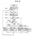
- FIG. 3 shows the operation of the program stored in the ROM 36 of the microcomputer 29, which was described in outline above, and the subroutines of which the flow charts are shown in Figs. 4A and 4B (to be described later) are called from this main programe.
- step 1 after the start of this main program, initialization of the RAM 12 of the microcomputer 29, as well as the actuators 9 through 12 for the shock absorber devices 1 through 4 for the wheels 5 through 8 respectively, is carried out, and in particular these actuators 9 through 12 are so controlled that the damping effectiveness of each of the shock absorber devices 1 through 4 is set to be at its minimum value. Then the flow of control passes to the step 2.
- step 2 data is (in fact sequentially) input to the RAM 37 of the microcomputer 29, through the input port device 38, representative of the current values of the output signals from the various sensors and switches described earlier, i.e. of the output signals from the mod select switch 25 and the mode select switch 26, from the vehicle speed sensor 14, from the steering sensor 17, from the throttle position sensor 19, from the stop lamp swtich 20 and from the neutral start switch 23; and thus this information is available to the CPU 37 henceforward, by inspection of the appropriate RAM locations.
- the overall program flow of this program consists of a cycle which returns to this step 2, and in fact this cycle is performed many tens of times per second, except when a delay is introduced during a subroutine called from the step 9 or during a subroutine called from the step 11 as will be explained later; so that up to date and current values of the signals from these various sensors and switches are always being consulted.
- the flow of control passes next to the step 3, in which the inputted data is preprocessed in preparation for the next stages of the proram; the details of this are not given because they are not critical for a general understanding of the system.
- the flow of control proceeds to the next step 4, which is a decision step.
- step 4 a decision is made as to whether the AUTO mode is currently selected by the vehicle driver or not, in other words as to whether the mode select signal currently being outputted from the mode select switch 25 is an ON signal or not. If the result of this decision is NO, so that the MANUAL operational mode is currently being selected, then the flow of control passes next to the step 5; whereas if the result of this decision is YES, so that the AUTO operational mode is currently being selected, then the flow of control passes next to the step 8.
- step 5 next in this step 5 a decision is made as to whether the normal fixed operational mode is currently selected by the vehicle driver or not, in other words as to whether the mode select signal currently being outputted from the other mode select switch 26 is an OFF signal or not. If the result of this decision is YES, so that the normal fixed operational mode is currently being selected, then the flow control passes next to the step 6; whereas if the result of this decision is NO, so that the sport fixed operational mode, rather than the normal fixed one, is currently being selected, then the flow of control passes next to the step 7.
- step 6 which as explained above is reached if and only if the operational mode currently selected by the vehicle driver is the normal fixed MANUAL. mode, then the microcomputer 29 outputs control signals to the actuators 9 through 12 for the shock absorber devices 1 through 4 for the wheels 5 through 8 respectively, via the output port device 39, such as to control said actuators 9 through 12 so that the damping effectiveness of each of the shock absorber devices 1 through 4 is set to be at its minimum value, as is appropriate in this normal fixed MANUAL mode operation.
- the flow of control of Fig. 3 program passes back to the step 2, to cycle again.
- step 6 which as explained above is reached if only and only if the operational mode currently selected by the vehicle driver is the sport fixed MANUAL mode, then the microcomputer 29 similarly outputs control signals to the actuators 9 through 12 for the shock absorber devices 1 through 4, such as to control said actuators 9 through 12 so that the damping effectiveness of each of the shock absorber devices 1 through 4 is set to be at its medium value, as is appropriate in this sport fixed MANUAL mode operation.
- the flow of control of the Fig. 3 program passes back to the step 2, to cycle again.
- step 8 a decision is made as to whether the normal base AUTO operational mode is currently selected by the vehicle driver or not, in other words as to whether the mode select signal currently being outputted from the other mode select switch 26 is an OFF signal or not. If the result of this decision is NO, so that the sport base AUTO operational mode, rather than the normal fixed one, is currently being selected, then the flow of control passes next to the step 9; whereas if the result of this decision is YES, so that the normal base operational mode is currently being selected, then the flow of control passes next to the step 10.
- step 10 at which point in the flow of the Fig. 3 program it has been determined that the normal base operational mode is currently being selected, next a decision is made as to whether the vehicle speed V is greater than a certain determinate value V1, or not.
- This decision is in order to establish whether the vehicle is currently in a high speed type operational situation, or not; typically the above mentioned determinate speed V1 may be about 80 kph. If the result of this decision is YES, so that the vehicle speed V is greater than V1, then the flow of control passes next to the step 9, so that the control is just as though the sport base AUTO operational mode was being selected by the driver; whereas if the result of this decision is NO, so that the vehicle speed V is less than V1, then the flow of control passed next to the step 11.
- the microcomputer 29 performs various appropriate calculations and decisions, and, according to the output signals from the various sensors described above and according to the current values of various vehicle operational parameters detected thereby, appropriately outputs control signals to the actuators 9 through 12 for the shock absorber devices 1 through 4 for the wheels 5 through 8 respectively, via the output port device 39, such as to control said actuators 9 through 12 so that the damping effectiveness of each of the shock absorber devices 1 through 4 is set to be at an appropriate value for these particular operating conditions, respectively between its medium value and its maximum value as is appropriate in the sport base AUTO operational mode, or between its minimum value and its medium value and its maximum value as is appropriate in the normal base AUTO operational mode.
- the flow of control of the Fig. 3 program passes back to the step 2 to cycle again as before of course only as long as the ignition switch of the vehicle is in the closed state.
- Fig. 5 is a type of phase space diagram in which vehicle speed is shown along the horizontal axis and steering angle is shown along the vertical axis, showing various phase space regions in the which roll limiting effect can be obtained in varying amounts by increase in the damping effectiveness of the shock absorbers: data corresponding to the information in this graph is determined in advance by experiment, and is stored in the ROM 36 of the microcomputer 29 in digital form.
- the region A of the phase space is a region of pairs of values of the vehicle speed and the turning angle (i.e.
- the region B is a phase space region in which such increase of the damping effectiveness of the shock absorber devices 1 through 4 has a much weaker but still perceptible roll limiting effect
- the region C is a phase space region in which such increase of the damping effectiveness of the shock absorber devices 1 through 4 has little or no perceptible roll limiting effect
- the region A' is a transitional region between the region A and the region B, while similarly the region B' is a transistional region between the region B and the region C.
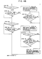
- the flow of control is shown as entering at the top of Fig. 4A, and first passes to the step 21.
- step 21 the damping effectiveness of each of the shock absorber devices 1 through 4 is set to its minimum value, by appropriate output of signals to the actuators 9 through 12 thereof via the output port device 39 by the microcomputer 29.
- step 22 the first of many decision steps.
- the flow of the remainder of this subroutine of Figs. 4A and 4B is as follows: the operational conditions of the vehicle are subjected in turn to four groups of tests, and if the condition of each test group in turn are not satisfied then the next such test group is performed.
- the flow of control passes from the left hand side of Fig. 4A or 4B to the right hand side, and the followng processes occur.
- the step 32, the step 37, or the step 41 the damping effectiveness of each of the shock absorber devices 1 through 4 is set to its maximum value, by appropriate output of signals to the actuators 9 through 12 thereof via the output port device 39 by the microcomputer 29. Then the flow of control enters a delay loop, which detains said control flow for a certain time period of the order of a few seconds until some particular condition is fulfilled.
- step 23 a decision is made as to whether a change of the operational conditions of the vehicle has led the point in the phase space of Fig. 5 representing said operational conditions from the region B' or from the region B to the region A, i.e. as to whether the phase space point representing the operational conditions of the vehicle in terms of vehicle speed and vehicle turning angle has transited from a region in which increase of the damping effectiveness of the shock absorbers 1 through 4 is moderately effective for decreasing vehicle body roll angle to a region in which said increase of damping effectiveness is clearly and definitely effective for thus decreasing vehicle body roll angle.
- this decision implemented by using certain flags and/ or variables, not particularly shown herein.
- step 24 is for initiating the provision of roll limiting effect by the preferred embodiment of the damping effectiveness control system according to the present invention.
- the damping effectiveness of each of the shock absorber devices 1 through 4 is set to its maximum value, by appropriate output of signals to the actuators 9 through 12 thereof via the output port device 39 by the microcomputer 29. This is effective for limiting the amount of body roll of the vehicle, as has already been decided by the first group of tests explained above.
- step 25 the flow of control passes to the step 25 to enter a delay loop, as follows: in the step 25 a decision is made as to whether a determined time interval t1, for example equal to two seconds, has elapsed since the point of the phase space of Fig. 5 transited from the region C either to the region B or to the region A', or not. Again, this decision is implemented by using certain flags and/or variables, not particularly shown herein.
- a determined time interval t1 for example equal to two seconds
- the flow of control is transferred back to the step 25 again, to perform a tight delay loop until the rsult of the decision becomes YES; whereas if the result of this decision is YES, so that now two seconds (exemplarily) have elapsed since shock absorber effectiveness increase for roll limitation was started, then the flow of control passes next to the step 26.
- this decision step 26 a decision is made as to whether a time period t2, for example equal to two seconds, has elapsed with the point in the phase space of Fig. 5 continuously outside the region A, or not. Again, this decision is implemented by using certain flags and/or variables, not particularly shown herein.
- the flow of control is transferred back to the step 25 again, to again perform a tight delay loop until the result of the step 26 decision becomes YES; whereas if the result of this decision is YES, so that now at least two seconds (exemplarily) have elapsed since shock absorber effectiveness increase for roll limitation ceased to be very effective, then the flow of control passes next to the step 27, shown in Fig. 4B. In the step 27, shown in Fig. 4B.
- this brief period on increase of damping effectiveness of the shock absorber devices 1 through 4 to the maximum value thereof provided as explained above by the program steps 24 through 26 is very effective in order to counteract vehicle body roll caused by sharp vehicle turning, when the vehicle is performing a turn within the limits of steering angle and vehicle speed which are liable to produce more than a certain amount of rolling; and when these limits of stearing angle and vehicle speed are left, after a certain determinate time the damping effectiveness of the shock absorber devices 1 through 4 is decreased back to its minimum value, in order to provide good ridability for the vehicle.
- this step 29 decision is implemented by using certian flags and/or varibles, not particularly shown herein. If the result of this decision is YES, so that now increase of the damping effectiveness of the shock absorbers 1 through 4 will be definitely effective for decreasing vehicle squat, and is now required, then the flow of control passes next to the step 32, whereas if the result of this decision is NO, so that vehicle jerk is judged to be at the present time not sufficient to cause any squat problem, then the flow of control passes next to the step 30.
- step 32 which is for initiating the provision of squat limiting effect by the preferred embodiment of the damping effectiveness control system according to the present invention.
- the damping effectiveness of each of the shock absorber devices 1 through 4 is set to its maximum value, by appropriate output of signals to the actuators 9 through 12 thereof via the output port deviced 39 by the microcomputer 29. This is effective for limiting the amount of body squat of the vehicle, as is required as just decided by the second group of tests explained above.
- the flow of control passes to the step 33, to enter a delay loop, as follows: in the step 33 a decision is made as to whether or not a determinate time interval t4, for example equal to two seconds, has elapsed since the decision occurred in the relevant step 29 or 31 from which control was just transferred to the previous step 32; in other words, in the case that control was transferred from the step 29 to the step 32 to reach this step 33, whether or not the determinate time t4 has elapsed since the throttle opening of the vehicle altered from at most the first determinate opening value thr1 to at least the second determinate opening value thr2 within the certain determinate time period t3, and, in the case that control was transferred from the step 31 to the step 32 to reach this step 33, whether or not the determinate time t4 has elapsed since the throttle opening of the vehicle altered to be above the third determinate opening value thr3.
- a determinate time interval t4 for example equal to two seconds
- this decision is implemented by using certain flags and/or variables, not particularly shown herein. If the result of this decision is YES, so that the shock absorber effectiveness increase for squat limitation has now been performed for two seconds, then the flow of control is transferred next to the step 27, shown in Fig. 4B and described above, and a shock absorber effectiveness increase for squat limitation is terminated. On the other hand, if the result of this decision is NO, so that as yet squat limitation has not yet been performed for (exemplarily) two seconds, then the flow of control passes next to the step 34.
- a certain determinate speed V4 for example 30 kph
- V5 another certain determinate speed
- the flow of control passes next to the step 36 which tests for such braking; whereas if the result of this decision is NO, so that the vehicle speed is judged to be too low for increase of the damping effectiveness of the shock absorbers 1 through 4, in the vent of hard vehicle braking, to be useful and effective for decreasing vehicle nose dive, then the flow of control passes next to the step 39, bypassing the step 36 and going directly to the step 39, to now start the fourth group of tests.
- step 37 which is for initiating the provision of nose dive limiting effect by the preferred embodiment of the damping effectiveness control system according to the present invention.
- the damping effectiveness of each of the shock absorber devices 1 thorugh 4 is set to its maximum value, by appropriate output of signals to the actuators 9 through 12 thereof via the output port device 39 by the microcomputer 29. This is effective for limiting the amount of nose dive of the vehicle, as is required as just decided by the third group of tests explained above.
- the flow of control passes to the step 38, to enter a delay loop, as follows.
- this brief period of increased damping effectiveness of the shock absorber devices 1 through 4 provided as explained above by the steps 37 and 38 is very effective in order to counteract vehicle nose dive caused by sharp vehicle braking, during vehicle operation in a medium to high speed operational region; and then the damping effectiveness of the shock absorber devices 1 through 4 is returned to the minimum value, in order to provide satisfactory vehicle ridability.
- V6 another certain determinate speed V6
- step 41 which is for initiating the provision of starting squat or tail lift limiting effect by the preferred embodiment of the damping effectiveness control system according to the present invention.
- the damping effectiveness of each of the shock absorber devices 1 through 4 is set to its maximum value, by appropriate output of signals to the actuators 9 through 12 thereof via the output port device 39 by the microcomputer 29. This is effective for limiting the amount of starting squat or tail lift of the vehicle, as is required as just decided by the fourth group of tests explained above.
- the flow of control passes to the step 42, to enter a delay loop, as follows: in the step 42 a decision is made as to . whether or not the vehicle road speed V is greater than equal to a certain determinate speed V7, for example 15 kph, i.e. as to whether the vehicle speed falls inside or outside a certain lower speed region in which starting squat or tail lift is a problem. If the result of this decision is YES, so that the region of problematical starting squat or tail lift has now definitely been left, then the flow of control is transferred next to the step 27, described above, and shock absorber effectiveness increase for starting squat or tail lift limitation is terminated.
- a certain determinate speed V7 for example 15 kph
- this decision step 43 a decision is made as to whether or not a determinate time interval t6, for example equal to five seconds, has elapsed since last the neutral starting switch 23 was in the on condition, i.e. since last the transmission of the vehicle has been engaged to any forward driving speed range. Again, this decision is implemented by using certain flags and/or variables, not particularly shown herein.
- the flow of control is transferred back to the step 42 again, to again perform a tight delay loop until the result of the step 42 decision or of the step 43 decision becomes YES; whereas if the result of this decision is YES, so that now the transmission of the vehicle has been out of any forward driving speed range for at least said determinate time period t6 of (exemplarily) five seconds, then the flow of control passes to the step 27, in which, as outlined previously, the damping effectiveness of each of the shock absorber devices 1 through 4 is reset to its minimum value; and then the flow of control returns to the main program of Fig.
- this brief period of increased damping effectiveness of the shock absorber devices 1 through 4 provided as explained above by the steps 41 through 43 is very effective in order to counteract vehicle starting squat or tail lift caused by vehicle acceleration from a very low vehicle speed or from rest; and then the damping effectiveness of the shock absorber devices 1 through 4 is returned to the minimum value, in order to provide satisfactory vehicle ridability.
- the damping effectivenesses of the shock absorber devices 1 through 4 are switched to and fro between their minimum values and their maximum values, being kept at their minimum values in order to provide satisfactory vehicle ridability at a well cushioned level, except when they are required to be increased to their maximum values in order to counteract the effects of vehicle roll, vehicle squat, vehicle nose dive, or vehicle starting squat or tail left.
- step 9 is the same as the step 11 subroutine just described, except that in the steps thereof corresponding to the steps 21 and 27 of said step 11 subroutine described above, rather than the damping effectiveness of each of the shock absorber devices 1 through 4 being set to its minimum value by appropriate output of signals to the actuators 9 through 12 thereof via the output port device 39 by the microcomputer 29, instead the damping effectiveness of each of the shock absorber devices 1 through 4 is in a similar fashion set to its medium value. And thus, in the steps of the Fig.
- the damping effectivenesses of the shock absorber devices are switched to and fro between their medium values and their maximum values, being kept at their medium values in order to provide satisfactory vehicle ridability at a relatively hard and sporty feeling level, except when they are required to be increased to their maximum values in order to counteract the effects of vehicle roll, vehicle squat, vehicle nose dive, or vehicle starting squat or tail lift.
- the above described series of four sets of tests respectively relating to provision of increased shock absorber effecti y eness for roll prevention, for squat prevention, for nose dive prevention, and for starting squat and tail lift prevention, could be performed in a different order, as long as the overall logic thereof was maintained.
- the present invention was shown as applied to a . vehicle incorporating an automatic transmission, the present invention should not be considered as being restricted to this application, but also could be applied to the case of a vehicle equipped with a manual transmission; and in such a case the steps 39 to 43 of the subroutine whose flow chart is shown in Fig. 4B would be omitted.
Landscapes
- Engineering & Computer Science (AREA)
- Mechanical Engineering (AREA)
- Vehicle Body Suspensions (AREA)
- Fluid-Damping Devices (AREA)
Applications Claiming Priority (2)
| Application Number | Priority Date | Filing Date | Title |
|---|---|---|---|
| JP59172146A JPS6150817A (ja) | 1984-08-18 | 1984-08-18 | 減衰力可変式ショックアブソ−バの減衰力制御装置 |
| JP172146/84 | 1984-08-18 |
Publications (3)
| Publication Number | Publication Date |
|---|---|
| EP0172272A2 EP0172272A2 (en) | 1986-02-26 |
| EP0172272A3 EP0172272A3 (en) | 1986-05-28 |
| EP0172272B1 true EP0172272B1 (en) | 1988-06-01 |
Family
ID=15936412
Family Applications (1)
| Application Number | Title | Priority Date | Filing Date |
|---|---|---|---|
| EP84115867A Expired EP0172272B1 (en) | 1984-08-18 | 1984-12-19 | Control system for three way variable shock absorber device for suspension with highest shock absorber effectiveness not selected in manual mode |
Country Status (4)
| Country | Link |
|---|---|
| US (1) | US4691284A (cg-RX-API-DMAC7.html) |
| EP (1) | EP0172272B1 (cg-RX-API-DMAC7.html) |
| JP (1) | JPS6150817A (cg-RX-API-DMAC7.html) |
| DE (1) | DE3471621D1 (cg-RX-API-DMAC7.html) |
Families Citing this family (45)
| Publication number | Priority date | Publication date | Assignee | Title |
|---|---|---|---|---|
| JPH07448B2 (ja) * | 1985-11-25 | 1995-01-11 | トヨタ自動車株式会社 | サスペンシヨン制御装置 |
| JPS62194921A (ja) * | 1986-02-21 | 1987-08-27 | Honda Motor Co Ltd | 緩衝器の減衰力制御方法 |
| JPH0780410B2 (ja) * | 1986-06-13 | 1995-08-30 | 日産自動車株式会社 | 車両用サスペンシヨン |
| US5144558A (en) * | 1986-06-13 | 1992-09-01 | Nissan Motor Company, Limited | Actively controlled automotive suspension system with adjustable rolling-stability and/or pitching-stability |
| JPH0723288Y2 (ja) * | 1986-06-30 | 1995-05-31 | 三菱自動車工業株式会社 | 車両用サスペンション装置 |
| DE3627549A1 (de) * | 1986-08-13 | 1988-02-18 | Daimler Benz Ag | Vorrichtung zum selbsttaetigen umschalten von fahrzeugaggregaten eines kraftfahrzeuges |
| US4809179A (en) * | 1987-01-20 | 1989-02-28 | Ford Motor Company | Control system for motor vehicle suspension unit |
| JP2575379B2 (ja) * | 1987-03-24 | 1997-01-22 | 日産自動車株式会社 | 能動型サスペンシヨン装置 |
| JPH0829649B2 (ja) * | 1987-03-31 | 1996-03-27 | 日産自動車株式会社 | 能動型サスペンシヨン装置 |
| DE3724271A1 (de) * | 1987-07-22 | 1989-02-02 | Bosch Gmbh Robert | Daempfungsvorrichtung |
| DE3867573D1 (de) * | 1987-09-03 | 1992-02-20 | Toyoda Chuo Kenkyusho Kk | Elektronisch geregeltes fluidumaufhaengungssystem mit vorausberechneter und rueckgekoppelter regelung der fahrzeuglage. |
| JPH0725245B2 (ja) * | 1987-09-04 | 1995-03-22 | 三菱自動車工業株式会社 | 車両用サスペンション装置 |
| DE3844838C2 (de) * | 1987-09-04 | 1994-03-31 | Mitsubishi Motors Corp | Fahrzeugaufhängung |
| JP2518349B2 (ja) * | 1988-04-19 | 1996-07-24 | トヨタ自動車株式会社 | 車輌用リヤサスペンション |
| JP2569714B2 (ja) * | 1988-04-19 | 1997-01-08 | トヨタ自動車株式会社 | 車輌用リヤサスペンション |
| FR2631480A1 (fr) * | 1988-05-16 | 1989-11-17 | Elf France | Procede et dispositifs d'automatisation et de simulation, en particulier pour motocycles |
| US5211420A (en) * | 1988-09-16 | 1993-05-18 | Honda Giken Kogyo Kabushiki Kaisha | Adjustable height suspension mechanism for two-wheeled motor vehicles |
| JPH02283512A (ja) * | 1989-04-22 | 1990-11-21 | Mitsubishi Electric Corp | サスペンション制御装置 |
| JP2514252B2 (ja) * | 1989-07-31 | 1996-07-10 | 日産自動車株式会社 | 能動型サスペンション |
| US5120982A (en) * | 1989-11-14 | 1992-06-09 | Ford Motor Company | Fault correcting circuit |
| US5137338A (en) * | 1991-02-11 | 1992-08-11 | Nartron Corporation | Combination vehicular braking and accessory control system |
| DE4115481C2 (de) * | 1991-05-11 | 2001-04-19 | Bosch Gmbh Robert | System zur Erhöhung des Fahrkomforts und der Fahrsicherheit |
| US5163705A (en) * | 1991-08-16 | 1992-11-17 | General Motors Corporation | Selectable damping vehicle suspension control responsive to transmission shift |
| US5186487A (en) * | 1991-08-16 | 1993-02-16 | General Motors Corporation | Selectable damping vehicle suspension control responsive to engine torque |
| US5163702A (en) * | 1991-08-16 | 1992-11-17 | General Motors Corporation | Selectable damping vehicle suspension control |
| JPH06115335A (ja) * | 1992-10-07 | 1994-04-26 | Toyota Motor Corp | 車輌の車体姿勢制御装置 |
| JP3171119B2 (ja) * | 1995-12-04 | 2001-05-28 | トヨタ自動車株式会社 | 車両の自動運転制御装置 |
| KR100702325B1 (ko) * | 2002-05-24 | 2007-03-30 | 주식회사 만도 | 전자제어 현가장치의 안티 스쿼트 제어방법 |
| US6879898B2 (en) * | 2003-01-03 | 2005-04-12 | General Motors Corporation | Method and apparatus for vehicle integrated chassis control system |
| US7165644B2 (en) * | 2004-03-18 | 2007-01-23 | Ford Global Technologies, Llc | Method and apparatus of controlling an automotive vehicle using brake-steer as a function of steering wheel torque |
| US20050206231A1 (en) * | 2004-03-18 | 2005-09-22 | Ford Global Technologies, Llc | Method and apparatus for controlling an automotive vehicle using brake-steer and normal load adjustment |
| US7229139B2 (en) * | 2004-03-18 | 2007-06-12 | Ford Global Technologies, Llc | Control system for brake-steer assisted parking and method therefor |
| US8380416B2 (en) | 2004-03-18 | 2013-02-19 | Ford Global Technologies | Method and apparatus for controlling brake-steer in an automotive vehicle in reverse |
| US7577508B2 (en) * | 2006-05-09 | 2009-08-18 | Lockheed Martin Corporation | Mobility traction control system and method |
| CA2651252A1 (en) * | 2006-05-09 | 2008-05-08 | Lockheed Martin Corporation | Mobility traction control system and method |
| US7831353B1 (en) * | 2006-09-21 | 2010-11-09 | Trw Automotive U.S. Llc | Vehicle control system and method of controlling a vehicle system |
| US8589049B2 (en) | 2007-12-03 | 2013-11-19 | Lockheed Martin Corporation | GPS-based system and method for controlling vehicle characteristics based on terrain |
| US8145402B2 (en) * | 2007-12-05 | 2012-03-27 | Lockheed Martin Corporation | GPS-based traction control system and method using data transmitted between vehicles |
| DE102009027939A1 (de) * | 2009-02-03 | 2010-08-05 | Robert Bosch Gmbh | Verfahren zur Fahrwerkregelung eines Kraftfahrzeugs, sowie Vorrichtung zur Durchführung |
| US8229639B2 (en) * | 2009-02-17 | 2012-07-24 | Lockheed Martin Corporation | System and method for stability control |
| US8352120B2 (en) | 2009-02-17 | 2013-01-08 | Lockheed Martin Corporation | System and method for stability control using GPS data |
| US8244442B2 (en) * | 2009-02-17 | 2012-08-14 | Lockheed Martin Corporation | System and method for stability control of vehicle and trailer |
| JP5463263B2 (ja) * | 2009-11-30 | 2014-04-09 | 日立オートモティブシステムズ株式会社 | 車両用サスペンション制御装置 |
| RU2524773C2 (ru) * | 2012-07-11 | 2014-08-10 | Вячеслав Васильевич Горбулин | Амортизатор электронно-регулируемый "аэр" |
| CN113752771B (zh) * | 2020-06-04 | 2024-05-17 | 广州汽车集团股份有限公司 | 汽车的抗点头控制方法、装置及相关设备 |
Family Cites Families (8)
| Publication number | Priority date | Publication date | Assignee | Title |
|---|---|---|---|---|
| US4333668A (en) * | 1979-12-17 | 1982-06-08 | The Bendix Corporation | Electronic adaptive ride control system |
| JPS57201707A (en) * | 1981-06-05 | 1982-12-10 | Nec Corp | Shock absorber |
| US4527676A (en) * | 1982-02-13 | 1985-07-09 | Atsugi Motor Parts Co., Ltd. | Variable-damping-force shock absorber |
| US4555126A (en) * | 1982-10-18 | 1985-11-26 | Mazda Motor Corporation | Vehicle suspension system |
| JPS59120509A (ja) * | 1982-12-27 | 1984-07-12 | Toyota Motor Corp | 車両のサスペンシヨン機構におけるシヨツクアブソ−バの減衰力制御装置 |
| US4586728A (en) * | 1983-02-28 | 1986-05-06 | Mazda Motor Corporation | Vehicle suspension means having variable suspension characteristics |
| JPS6034905U (ja) * | 1983-08-19 | 1985-03-09 | 三菱自動車工業株式会社 | 電子制御サスペンシヨン |
| JPS6069711U (ja) * | 1983-10-20 | 1985-05-17 | トキコ株式会社 | 減衰力調整式油圧緩衝装置 |
-
1984
- 1984-08-18 JP JP59172146A patent/JPS6150817A/ja active Granted
- 1984-12-14 US US06/681,586 patent/US4691284A/en not_active Expired - Lifetime
- 1984-12-19 EP EP84115867A patent/EP0172272B1/en not_active Expired
- 1984-12-19 DE DE8484115867T patent/DE3471621D1/de not_active Expired
Also Published As
| Publication number | Publication date |
|---|---|
| JPS6150817A (ja) | 1986-03-13 |
| JPH0446769B2 (cg-RX-API-DMAC7.html) | 1992-07-31 |
| DE3471621D1 (en) | 1988-07-07 |
| EP0172272A2 (en) | 1986-02-26 |
| US4691284A (en) | 1987-09-01 |
| EP0172272A3 (en) | 1986-05-28 |
Similar Documents
| Publication | Publication Date | Title |
|---|---|---|
| EP0172272B1 (en) | Control system for three way variable shock absorber device for suspension with highest shock absorber effectiveness not selected in manual mode | |
| EP0269132B1 (en) | Combined power steering and variable suspension control arrangement | |
| US6006151A (en) | Controller for an automatic transmission in a motor vehicle | |
| US5632503A (en) | Method for allowing enhanced driver selection of suspension damping and steering efforts | |
| JP2701429B2 (ja) | 自動変速機の制御装置 | |
| JP4938542B2 (ja) | 車両の車速制御装置 | |
| US6879898B2 (en) | Method and apparatus for vehicle integrated chassis control system | |
| JP2532059B2 (ja) | 車両のサスペンシヨン制御装置 | |
| US5390117A (en) | Transmission control with a fuzzy logic controller | |
| US6099086A (en) | Setpoint generator for control of an electrically controlled brake system | |
| US4797823A (en) | System for vehicle body roll control performing suspension hardness control | |
| JP3010892B2 (ja) | 車両のサスペンション制御装置 | |
| GB2285876A (en) | Method for gradually classifying driving styles and motor vehicle using this method | |
| JPH0811484B2 (ja) | 車両のサスペンシヨン制御装置 | |
| US20050090963A1 (en) | Device for controlling at least one control and/or regulating system arranged in a vehicle | |
| KR100384646B1 (ko) | 자동차내부장치를위한제어기 | |
| CN108662138B (zh) | 车辆用自动变速器的控制装置 | |
| JP3019384B2 (ja) | サスペンション制御装置 | |
| JPH0569723B2 (cg-RX-API-DMAC7.html) | ||
| JP3119284B2 (ja) | 車両用サスペンション制御装置 | |
| JP3119286B2 (ja) | 車両用サスペンション制御装置 | |
| JPS62151655A (ja) | 自動変速制御装置 | |
| JPH05169957A (ja) | サスペンション制御装置 | |
| JPH0696362B2 (ja) | 車両のサスペンシヨン制御装置 | |
| JP3094750B2 (ja) | 車両用サスペンション制御装置 |
Legal Events
| Date | Code | Title | Description |
|---|---|---|---|
| PUAI | Public reference made under article 153(3) epc to a published international application that has entered the european phase |
Free format text: ORIGINAL CODE: 0009012 |
|
| AK | Designated contracting states |
Designated state(s): DE FR GB |
|
| PUAL | Search report despatched |
Free format text: ORIGINAL CODE: 0009013 |
|
| AK | Designated contracting states |
Kind code of ref document: A3 Designated state(s): DE FR GB |
|
| 17P | Request for examination filed |
Effective date: 19860520 |
|
| 17Q | First examination report despatched |
Effective date: 19870313 |
|
| GRAA | (expected) grant |
Free format text: ORIGINAL CODE: 0009210 |
|
| AK | Designated contracting states |
Kind code of ref document: B1 Designated state(s): DE FR GB |
|
| REF | Corresponds to: |
Ref document number: 3471621 Country of ref document: DE Date of ref document: 19880707 |
|
| ET | Fr: translation filed | ||
| PLBE | No opposition filed within time limit |
Free format text: ORIGINAL CODE: 0009261 |
|
| STAA | Information on the status of an ep patent application or granted ep patent |
Free format text: STATUS: NO OPPOSITION FILED WITHIN TIME LIMIT |
|
| 26N | No opposition filed | ||
| REG | Reference to a national code |
Ref country code: GB Ref legal event code: 746 Effective date: 19931026 |
|
| REG | Reference to a national code |
Ref country code: FR Ref legal event code: D6 |
|
| PGFP | Annual fee paid to national office [announced via postgrant information from national office to epo] |
Ref country code: DE Payment date: 20001211 Year of fee payment: 17 |
|
| PGFP | Annual fee paid to national office [announced via postgrant information from national office to epo] |
Ref country code: FR Payment date: 20001212 Year of fee payment: 17 |
|
| PGFP | Annual fee paid to national office [announced via postgrant information from national office to epo] |
Ref country code: GB Payment date: 20001213 Year of fee payment: 17 |
|
| PG25 | Lapsed in a contracting state [announced via postgrant information from national office to epo] |
Ref country code: GB Free format text: LAPSE BECAUSE OF NON-PAYMENT OF DUE FEES Effective date: 20011219 |
|
| REG | Reference to a national code |
Ref country code: GB Ref legal event code: IF02 |
|
| PG25 | Lapsed in a contracting state [announced via postgrant information from national office to epo] |
Ref country code: DE Free format text: LAPSE BECAUSE OF NON-PAYMENT OF DUE FEES Effective date: 20020702 |
|
| GBPC | Gb: european patent ceased through non-payment of renewal fee |
Effective date: 20011219 |
|
| PG25 | Lapsed in a contracting state [announced via postgrant information from national office to epo] |
Ref country code: FR Free format text: LAPSE BECAUSE OF NON-PAYMENT OF DUE FEES Effective date: 20020830 |
|
| REG | Reference to a national code |
Ref country code: FR Ref legal event code: ST |