EP0171902A1 - Vorrichtung zur Regulierung der Konzentration einer Flüssigkeitsentwicklungseinrichtung - Google Patents
Vorrichtung zur Regulierung der Konzentration einer Flüssigkeitsentwicklungseinrichtung Download PDFInfo
- Publication number
- EP0171902A1 EP0171902A1 EP19850304655 EP85304655A EP0171902A1 EP 0171902 A1 EP0171902 A1 EP 0171902A1 EP 19850304655 EP19850304655 EP 19850304655 EP 85304655 A EP85304655 A EP 85304655A EP 0171902 A1 EP0171902 A1 EP 0171902A1
- Authority
- EP
- European Patent Office
- Prior art keywords
- concentration
- liquid
- liquid developer
- developing
- pipe
- Prior art date
- Legal status (The legal status is an assumption and is not a legal conclusion. Google has not performed a legal analysis and makes no representation as to the accuracy of the status listed.)
- Granted
Links
- 239000007788 liquid Substances 0.000 title claims abstract description 157
- 230000000977 initiatory effect Effects 0.000 claims description 2
- 238000011144 upstream manufacturing Methods 0.000 claims description 2
- 230000001603 reducing effect Effects 0.000 claims 1
- 230000009471 action Effects 0.000 abstract description 7
- 238000001514 detection method Methods 0.000 description 8
- 239000002245 particle Substances 0.000 description 8
- 238000011084 recovery Methods 0.000 description 7
- 230000003247 decreasing effect Effects 0.000 description 6
- 238000005070 sampling Methods 0.000 description 6
- 239000002904 solvent Substances 0.000 description 6
- 230000005540 biological transmission Effects 0.000 description 5
- 230000004044 response Effects 0.000 description 4
- 230000008021 deposition Effects 0.000 description 3
- 230000009467 reduction Effects 0.000 description 3
- 238000010586 diagram Methods 0.000 description 2
- 238000005259 measurement Methods 0.000 description 2
- 238000000034 method Methods 0.000 description 2
- 238000012986 modification Methods 0.000 description 2
- 230000004048 modification Effects 0.000 description 2
- 230000008569 process Effects 0.000 description 2
- 239000013589 supplement Substances 0.000 description 2
- 238000009834 vaporization Methods 0.000 description 2
- 230000008016 vaporization Effects 0.000 description 2
- 239000003570 air Substances 0.000 description 1
- 239000012080 ambient air Substances 0.000 description 1
- 230000003321 amplification Effects 0.000 description 1
- 238000009833 condensation Methods 0.000 description 1
- 230000005494 condensation Effects 0.000 description 1
- 230000008020 evaporation Effects 0.000 description 1
- 238000001704 evaporation Methods 0.000 description 1
- 239000000463 material Substances 0.000 description 1
- 238000003199 nucleic acid amplification method Methods 0.000 description 1
- 230000000630 rising effect Effects 0.000 description 1
- 230000035945 sensitivity Effects 0.000 description 1
- 230000001502 supplementing effect Effects 0.000 description 1
Images


Classifications
-
- G—PHYSICS
- G03—PHOTOGRAPHY; CINEMATOGRAPHY; ANALOGOUS TECHNIQUES USING WAVES OTHER THAN OPTICAL WAVES; ELECTROGRAPHY; HOLOGRAPHY
- G03G—ELECTROGRAPHY; ELECTROPHOTOGRAPHY; MAGNETOGRAPHY
- G03G15/00—Apparatus for electrographic processes using a charge pattern
- G03G15/06—Apparatus for electrographic processes using a charge pattern for developing
- G03G15/10—Apparatus for electrographic processes using a charge pattern for developing using a liquid developer
- G03G15/104—Preparing, mixing, transporting or dispensing developer
- G03G15/105—Detection or control means for the toner concentration
-
- Y—GENERAL TAGGING OF NEW TECHNOLOGICAL DEVELOPMENTS; GENERAL TAGGING OF CROSS-SECTIONAL TECHNOLOGIES SPANNING OVER SEVERAL SECTIONS OF THE IPC; TECHNICAL SUBJECTS COVERED BY FORMER USPC CROSS-REFERENCE ART COLLECTIONS [XRACs] AND DIGESTS
- Y10—TECHNICAL SUBJECTS COVERED BY FORMER USPC
- Y10T—TECHNICAL SUBJECTS COVERED BY FORMER US CLASSIFICATION
- Y10T137/00—Fluid handling
- Y10T137/2496—Self-proportioning or correlating systems
- Y10T137/2499—Mixture condition maintaining or sensing
- Y10T137/2509—By optical or chemical property
Definitions
- the present invention relates generally to a liquid developing apparatus for developing a electrostatic latent image in facsimiles, copying machines, printers or the like.
- the invention concerns a device or apparatus for controlling concentration in the liquid developing machine so that concentration of a liquid developer be constantly maintained to be constant.
- a liquid developer having fine colored particles termed toner dispersed in a solvent to be thereby visualized.
- Repetition of development results in decreasing of quantity of toner in the solvent, lowering concentration of the developer.
- concentration of development i.e. concentration of developer as well as density of developed image
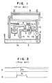
- Fig. 1 of the accompanying drawing shows a typical one of the hitherto known developing machine equiped with a concentration controlling apparatus for maintaining constant the concentration of a liquid developer.
- the known liquid developing machine includes a lift pump 2 for feeding a developing liquid (also referred to as liquid developer ) 3a contained in a tank 3 to a developing container 1 through a pipe 10.
- a developing liquid also referred to as liquid developer
- An electrostatic latent image on a recording sheet 8 is visualized by the developing liquid fed to fill the developing container 1.
- a pipe 11a is branched from the pipe 10 through which the developing liquid is fed upwardly and is equiped with a concentration detecting device 4 which is composed of a transparent pipe section 4a combined with a light emitting element 4b and a photoelectric sensor element 4c disposed on both sides of the transparent pipe section in diametrical opposition to each other.
- the developing liquid 3a also flows through the branch pipe lla, whereby concentration of the developing liquid is detected.
- the pipe lla is connected to a toner supplementing apparatus composed of a Venturi tube 5, a valve 7 and a pipe 9. Under the pressure of the liquid developer 3a flowing through the pipe lla, a negative pressure or vacuum . is produced by the Venturi tube 5 so that a negative pressure prevails within the pipe 9.
- the other end of the pipe 9 is immersed in a pool of concentrated toner 6.
- the concentrated toner 6 is supplementarily supplied to the tank or container 3 by way of the pipe 9, the Venturi tube 5 and a pipe 11b.
- the concentration detecting device 4 and the valve 7 is connected to a concentration controlling circuit 26a.
- the concentration detector responds to activate the concentration controlling circuit 26a in such a manner that the valve 7 is opened. In this state, the ambient air flows in the valve 7, causing the supplementary supply of the concentrated toner 6 to be stopped.
- the concentration controlling circuit 26a is composed of an amplifier circuit for amplifying the output signal of the concentration detector 4, a comparator for comparing the amplified output signal of the concentration detector 4 with a reference voltage and an electromagnetic valve controlling circuit for controlling the closing and opening operations of an electromagnetic or solenoid valve 7 in dependence on the output signal of the comparator.
- a control signal is supplied to the electromagnetic valve controlling circuit which responds thereto for producing a signal which triggers the opening or closing operation of the valve 7.
- Fig. 2 is a timing chart for illustrating the timing in the operation described above.
- the output signal of the amplifier circuit is shown at A
- the reference voltage value is indicated by Vo
- the output signal of the electromagnetic valve controlling circuit is shown at B.
- the valve 7 is closed.
- the concentrated toner 6 is added to the developing liquid 3a, as the result of which the amount of light transmitting through the transparent pipe section 4a is decreased. Consequently, the output level of the detecting signal amplifying circuit is correspondingly lowered, indicating that concentration of the developing liquid 3a is increased.
- the hitherto known liquid developing machine is however disadvantageous in that the negative pressure or vacuum can not be generated with high effiency or sensitivity due to such structure in which the Venturi tuve 5 is connected in parallel with the developing container 1 on the discharge side of the lift pump 2 so that the negative pressure is produced upon flowing of the discharged liquid developer 3a. Further, disposition and connection of the Venturi tube and the pipes 10a, 11a and 11b involve a complicated structure, an increased size of the machine and expensiveness thereof.
- the concentration controller employed in the known liquid developing machine mentioned above is so arranged . as to actuate or close the valve 7 in response to detection of lowered toner concentration of the developing liquid to thereby allow the concentrated toner to be added to the developing liquid under the action of the Venturi tube, While upon detection of the toner concentration having reached at the reference value, the valve 7 is actuated (opened) to stop the addition of the concentrated toner 6.
- the concentrated toner flowing though the pipe 9, the Venturi tube 5 and the pipe 11 at the time when the valve is opened is supplied to the developer tank 3 in excess, bringing about possibly an excessively high density of the toner particles in the liquid developer 3a. As the consequence, background fog and condensation of toner particles often take place, to a serious problem.
- An object of the present invention is to overcome the problems of the prior art developing machine described above and to provide a liquid developing apparatus in which the Venturi tube can be omitted from the concentration controlling system while piping arrangement can be simplified.
- Another object of the present invention is to provide a liquid developing apparatus equipped with a concentration contol system which is capable of maintaining concentration ( density of toner particles ) of a developing liquid constantly at a correct or proper level or value.
- a further object of the invention is to provide a device or apparatus for controlling concentration in liquid developing machine in which concentration of the developing liquid can be detected with high accuracy and improved reliability even in the case where a device for detecting concentration of the developing liquid is provided in a liquid deloper supply pipe at an intermediate portion thereof.
- a pressure reduction pump or vacuum pump is connected to a liquid developer circulating pipe for circulating a developing liquid between a strage tank and a developing container, wherein a pipe extending from a toner container containing concentrated toner liquid is connected to the vacuum pump at the suction side thereof, while a valve device (which may be operated manually or automatically ) is installed in said pipe.
- the valve device may be constituted by electromagnetic or solenoid valve or the like which can rapidly respond to the signal available from the output of a concentration detector, whereby the concentration control can be performed smoothly and uniformly.
- the concentration controller used in combination with the liquid developing machine is provided with control means for responding to a signal supplied from the concentration detector to thereby actuate intermittently the valve device for supplying the concentrated toner liquid over a predetermined time span, whereby the supplementary supply of the concentrated toner is repeatedly performed on a bit-by-bit basis over the predetermined time span.
- density of the toner particles dispersed in the developing liquid i.e. concentration of the developing liquid
- that portion of the liquid developer supplying pipe where the concentration detecting means is disposed is additionally provided with means for stagnating constsntly the liquid developer.
- FIG. 3 shows a general arrangement of the liquid developing machine having device for controlling concentration therein according to a first exemplary embodiment of the present invention
- Figs 4 and 5 are, respectively, a plan view and a perspective view showing a developing device employed in the apparatus shown in Fig. 3.
- a developing device or container 12 is connected to a suction or lift pipe 17 for lifting a liquid developer 14a from a liquid developer containing tank 14.
- the pipe 17 constitutes a part of the liquid developer circulating pipe system and is provided with a transparent section 17a in the vicinity of which a light emitting element 18a (a lamp is the case of the illustrated embodiment) and a photoelectric sensor 18b serving as a light receiving element are disposed to constitute a concentration detector 18 for detecting concentra- ion of the liquid developer.
- the developing device 12 includes a developing slit 20 and squeeze slits 21a and 21b, as shown in Figs. 4 and 5, wherein one end (lefthand end as viewed in the figure) of the developing slit 20 is connected to the lift or suction pipe 17.
- the other end of the slit 20 (righthand end as viewed in the figure) is integrally combined with corresponding end portions of the squeeze slits 21a and 21b and connected to a pipe 24 for recovery of the liquid developer.
- a reference numeral 23 denotes an electrostatic head for forming an electrostatic latent image on an electrostatic type recording sheet 19.
- the recovery pipe 24 is equiped with a vacum pump (P) 13. Under the action of this pump 13, the liquid developer 14a is discharged from the developing device or container 12 to be returned to the tank 14a.
- P vacum pump
- a pipe 22 is branched from the recovery pipe 24 and has a free end portion immersed in a pool of a concentrated toner liquid 15a, so that the toner liquid 15a is lifted or sucked upwardly through the pipe 24 under a negative pressure produced by the vacuum pump 13.
- a reference numeral 15 denotes a toner container for storing therein the concentrated toner liquid 15a.
- the branch pipe 22 is provided with a valve device which may be constituted by a manually operated valve or an automatically operated valve.
- an electromagnetic or solenoid valve 16 is employed and constitutes a concentration controller in cooperation with the concentration detector 18 and a concentration control circuit 26b which cooperates with the concentration detector 18 as will be described hereinafter.
- an electrostatic latent image is first formed on the recording sheet 19 by means of the electrostatic head 23 shown in Fig. 5. Subsequently, the electrostatic type recording sheet 19 is transported in the direction indicated by an arrow by transporting means (not shown) to a position over the developing container 12.
- the vacuum pump 13 is operated, whereby the pressure within the developing container 12 is reduced.
- the developing liquid 14a is lifted through the suction pipe 17 from the tank 14 to fill the developing container 12 with the liquid developer, whereby the electrostatic latent image on the recording sheet 19 is visualized or developed.
- the developing liquid 14a which has undergone consumption of the toner through the development is returned to the tank 14 by way of the vacuum pump 13 and the recovery pipe 24.
- the squeeze slits 21a and 21b of the developing container 12 are not connected to the suction pipe 17 but con- . nected only to the vacuum pump 13, differing from the case of the developing slit 20. Accordingly, no developing liquid 14a flows through the squeeze slits 21a and 21b, which are however in the pressure reduced state under the action of the vacuum pump 13.
- the developing liquid in excess deposited on the electrostatic type recording sheet which has reached the squeeze slit 21b is caused to be separated from the recording sheet 19 under the action of an air stream flowing between the developing container 12 and the recording sheet 19 and caught by the squeeze slit 21b to be returned to the liquid developer tank 14 by way of the vacuum pump 13.
- the recording sheet undergone the development through the developing slit 20 is get rid of the developing liquid in excess upon passing through the squeeze slit 21b to be transported in the dried state.
- the concentration detector 18 serves to detect concentration of the developing liquid 14a flowing through the suction pipe 17 toward the developing container 12. More specifically, the developing liquid flowing through the pipe 17 is illuminated with the lamp 18a, wherein the light transmitting through the pipe section 17a and the liquid developer 14a is received by the photoelectric sensor 18b. When the amount of light received by the sensor 18b is increased beyond a present reference value, the electromagnetic or solenoid valve 16 is opened under the control of the concentration control circuit 26b.
- the concentration detector 18 is activated to start the measurement of the amount of light transmission.
- the amount of light transmission is large, it is decided that the developing liquid is thinner as compared with the reference concentration, resulting in that a signal is supplied to open the solenoid valve 16. Since the branch pipe 22 is reduced in pressure under the action of the vacuum pump 13, the concentrated toner liquid 15a is lifted through the branch pipe 22 from the toner container 15 to be supplied to the developing liquid tank 14.
- concentration of the liquid developer 14a within the tank 14 is thus increased to attain the reference concentration, the amount of light transmission is decreased as compared with that obtained through the preceding measurement. This decrease in light transmission is detected by the concentration detector 18, whereupon the electromagnetic or solenoid valve 16 is closed under the control of the concentration control circuit. The supplement of toner is thus completed.
- the output signal of the concentration detector 18 is sampled periodically at a predetermined time interval to control the period during which the electromagnetic valve 16 is opened, when concentration become lower than the reference value, to thereby realize more effective supplementary addition of the toner.
- Fig. 6 shows in a block diagram a circuit configuration of a concentration control circuit 26b which is improved over the concentration control circuit 26a.shown in Fig. 1.
- a reference symbol 18a denotes a light emitting lamp
- 25 denotes a lamp driving circuit
- 18b denotes a photoelectric sensor
- 27 denotes a preamplifier for amplifying the output signal voltage of the photoelectric sensor
- 28 denotes a sampling circuit for sampling periodically at a . predetermined time interval the output signal voltage of the sensor 18b after amplification through the amplifier 27.
- a numeral 29 denotes a comparator circuit for comparing the output signal of the sampling circuit 28 with a reference voltage
- 30 denotes a timing generator circuit for generating a timing signal for initiating the concentration control and a timing signal for the concentration detection, i.e. the timing signal for determining the sampling interval
- 31 denotes an electromagnetic valve control circuit which responds to the output signal of the comparator circuit for generating a control signal to open and close the electromagnetic or solenoid valve 16.
- Fig. 7 shows a timing chart.
- reference letters C and D designate two timing signal or periodical pulse signals generated by the timing generator circuit 30.
- the timing signal shown at C in Fig. 7 has a sufficiently long period T 1
- the timing signal illustrated at D is generated in synchronism with the leading edge of the timing pulse shown at C and includes a number of pulses (five pulses in the case of the illustrated embodiment) each having a shorter period T 2 than that (T 1 ) of the . timing signal D.
- the timing signal C determines the timing at which the control of concentration of the liquid developer is initiated, while the timing signal D determines the timing at which concentration of the developing liquid is to be detected and the timing at which the concentrated toner liquid is to be supplementarily added.
- This signal G is compared with the reference voltage signal V o ( represented by G' in Fig. 6) through the comparator circuit 29, as the result of which the pulse signal H produced when the signal G is of higher peak value than the reference voltage signal V o is supplied to the solenoid valve control circuit 31.
- a pulse signal I of a period T 3 is generated in response to the signal H applied from the comparator circuit 29, whereby the electromagnetic or solenoid valve 16 is opened for a time duration corresponding to the period T 3 .
- the concentrated toner liquid 15a is supplied to the liquid developer tank 14.
- the time duration corresponding to the period T 3 of the pulse signal I is so set that a small amount of the concentrated toner liquid is supplied and that concentration of the liquid developer 14a does not exceed the reference value to any appreciable degree through a single addition of the toner during the period T 3 . More specifically, after the concentrated toner liquid 15a is supplied during the period T 3 , concentration of the liquid developer is measured again. At that time, if concentration as detected does not attain the reference level, the concentrated toner liquid 15a is again supplied for the period T 3 . This operation is repeated until concentration of the liquid developer has attained the reference value.
- the concentrated toner adding means is actuated intermittently for a predetermined duration for controlling concentration of the.liquid developer in response to the detected concentration.
- Fig. 8 shows a developing machine according to a second embodiment of the invention.
- the concentration detector 18 constituting the means for detecting concentration. of the liquid developer is arranged on the liquid developer suction pipe 17 at an intermediate portion which constitutes a part of a U-like pipe section 17b serving as a liquid developer stagnating mean.
- a normally closed solenoid (electromagnetic) valve 41 is installed in the suction pipe 17 at a position downstream of the concentration detector 18.
- the concentration detector 18 it is possible to install the concentration detector 18 at a portion of the pipe 17 rising up from the developer tank 14 or at the bottom of the U-like pipe section 17b.
- the electromagnetic valve 41 is first closed, whereby the lifting or suction of the liquid developer 14a from the tank 14 is stopped. Subsequently, the liquid developer remaining within the developing slit 20 of the developing container 12 is recovered to the tank 14 through a recovery pipe 24 under the suction exerted by the vacuum pump 13, which is followed by the stoppage of the vacuum pump 13.
- the inner wall of the transparent pipe section 17a operatively combined with the concentration 18 is always wetted with the developing liquid, to prevent the toner contained in the liquid developer from being deposited on the wall of the transparent pipe section in the. dried state.
- the electromagnetic valve 41 disposed downstream - of the U-like pipe section 17b closes the suction pipe 17 at the top portion thereof at the end of the developing process, the liquid developer remaining within the suction pipe 17 is protected from vaporization, which in turn assists in preventing deposition of the toner on the inner wall of the pipe in dried state. Accordingly, in the application where the developing machine is not left unused for such an extended time that the liquid developer remaining in the upper portion of the suction pipe downstream of the electromagnetic valve 18 is all vaporized, the electromagnetic valve 41 may be spared.
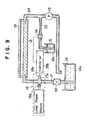
- Fig. 9 shows a developing machine according to a third embodiment of the present invention.
- a normally closed electromagnetic valve 42 is installed on the suction pipe 17 of a straight configuration at a location upstream of the concentration detector 18.
- the electromagnetic valve 42 By closing the electromagnetic valve 42 upon completion of a development process, the liquid developer can remain within the portion of the suction pipe 17 located downstream of the electromagnetic valve 42, whereby deposition of toner on the transparent pipe section 17a operatively combined with the concentration detector 18 due to evaporation of the solvent of developer can be prevented.
- an electromagnetic valve 41 similar to the valve..41 shown in Fig. 8 can be disposed on the suction pipe 17 at a location downstream of the concentration detector 18.
- a transmission type photoelectric sensor device is employed as the concentration detector. It can be understood - that a reflection type sensor may also be used to this end.
- the transparent wall section of the pipe operatively combined with the concentration detecting means is constantly wetted with the developing liquid, whereby,toner deposition on the that portion of the pipe due to vaporization of the solvent of the liquid developer can be positively prevented or suppressed.
- other constitutent components are same as or equivalent to those of the first embodiment and denoted by like reference symbols. Repetition of detailed description of these components will be unnecessary.
Landscapes
- Physics & Mathematics (AREA)
- General Physics & Mathematics (AREA)
- Wet Developing In Electrophotography (AREA)
Applications Claiming Priority (6)
| Application Number | Priority Date | Filing Date | Title |
|---|---|---|---|
| JP13566584A JPS6114666A (ja) | 1984-06-29 | 1984-06-29 | 液体現像装置 |
| JP13566784A JPS6114667A (ja) | 1984-06-29 | 1984-06-29 | 液体現像装置の濃度制御装置 |
| JP135665/84 | 1984-06-29 | ||
| JP135667/84 | 1984-06-29 | ||
| JP2036685A JPS61179481A (ja) | 1985-02-05 | 1985-02-05 | 液体現像装置 |
| JP20366/85 | 1985-02-05 |
Publications (2)
| Publication Number | Publication Date |
|---|---|
| EP0171902A1 true EP0171902A1 (de) | 1986-02-19 |
| EP0171902B1 EP0171902B1 (de) | 1990-09-05 |
Family
ID=27283004
Family Applications (1)
| Application Number | Title | Priority Date | Filing Date |
|---|---|---|---|
| EP19850304655 Expired - Lifetime EP0171902B1 (de) | 1984-06-29 | 1985-06-28 | Vorrichtung zur Regulierung der Konzentration einer Flüssigkeitsentwicklungseinrichtung |
Country Status (3)
| Country | Link |
|---|---|
| US (1) | US4671309A (de) |
| EP (1) | EP0171902B1 (de) |
| DE (1) | DE3579534D1 (de) |
Cited By (3)
| Publication number | Priority date | Publication date | Assignee | Title |
|---|---|---|---|---|
| EP0589653A3 (de) * | 1992-09-22 | 1994-10-12 | Xerox Corp | Tonerkonzentrationsmessung mit Selbsteichung. |
| EP0929009A3 (de) * | 1998-01-13 | 2001-03-28 | NEC Corporation | Tonerdichtedetektor, Tintenstrahlkopf, Entwicklungseinheit und Bilderzeugungsgerät wobei dieser Detektor verwended wird |
| WO2024129124A1 (en) * | 2022-12-15 | 2024-06-20 | Hewlett-Packard Development Company, L.P. | Reducing particle size distribution in a printing fluid |
Families Citing this family (17)
| Publication number | Priority date | Publication date | Assignee | Title |
|---|---|---|---|---|
| US4714087A (en) * | 1987-03-27 | 1987-12-22 | Jones Jamieson B | Fuel additive proportioning apparatus and method |
| US4857750A (en) * | 1987-12-17 | 1989-08-15 | Texas Instruments Incorporated | Sensor for determining photoresist developer strength |
| US5329338A (en) * | 1991-09-06 | 1994-07-12 | Xerox Corporation | Optical transparency detection and discrimination in an electronic reprographic printing system |
| US5369476A (en) * | 1992-01-28 | 1994-11-29 | Cactus | Toner control system and method for electrographic printing |
| US5623715A (en) * | 1994-08-23 | 1997-04-22 | Clark; Lloyd D. | Liquid toner concentrate management system and method |
| DE69818125T2 (de) * | 1997-02-27 | 2004-06-17 | Hitachi, Ltd. | Aufzeichnungsgerät mit Ionenflusskopf und Flüssigentwicklung |
| JP3022823B2 (ja) * | 1997-10-08 | 2000-03-21 | 新潟日本電気株式会社 | 液体濃度検出装置 |
| KR100322554B1 (ko) * | 1998-03-06 | 2002-06-24 | 윤종용 | 습식인쇄기의현상액농도측정장치 |
| US5960231A (en) * | 1998-11-03 | 1999-09-28 | Xerox Corporation | Variable thickness concentrate sense window |
| JP2000304693A (ja) * | 1999-04-16 | 2000-11-02 | Nec Niigata Ltd | 現像液の濃度測定方法、その装置および転写装置 |
| JP2001042652A (ja) * | 1999-08-03 | 2001-02-16 | Nec Niigata Ltd | インク濃度調整機構およびこのインク濃度調整機構を備えた電子写真装置 |
| US6616760B2 (en) * | 1999-12-17 | 2003-09-09 | Tokyo Electron Limited | Film forming unit |
| JP4194541B2 (ja) * | 2004-08-05 | 2008-12-10 | 東京エレクトロン株式会社 | 液処理装置、液処理方法及び液状態検出装置 |
| JP4735462B2 (ja) * | 2006-07-27 | 2011-07-27 | 株式会社日立製作所 | 導電パターン形成装置と導電パターン形成方法 |
| JP4735591B2 (ja) * | 2007-04-03 | 2011-07-27 | 株式会社日立製作所 | 導電パターン形成装置 |
| JP6324917B2 (ja) * | 2015-03-03 | 2018-05-16 | 富士フイルム株式会社 | 液体供給装置及び画像形成装置 |
| JP6983709B2 (ja) * | 2018-03-29 | 2021-12-17 | 株式会社日立製作所 | 分析システム、及び分析方法 |
Citations (6)
| Publication number | Priority date | Publication date | Assignee | Title |
|---|---|---|---|---|
| US3381662A (en) * | 1962-11-27 | 1968-05-07 | Harris Intertype Corp | Electrophotographic micro-copy printer |
| US3540409A (en) * | 1967-08-21 | 1970-11-17 | Varian Associates | Electrographic liquid inker employing a vacuum head and means for rapidly valving off the head |
| US3739800A (en) * | 1971-05-04 | 1973-06-19 | Copystatics Mfg Corp | Toner supply system for copying machine |
| US4119989A (en) * | 1977-01-03 | 1978-10-10 | Pitney-Bowes, Inc. | System for controlling concentration of developer solution |
| US4222497A (en) * | 1976-03-22 | 1980-09-16 | Xerox Corporation | System and method for monitoring and maintaining a predetermined concentration of material in a fluid carrier |
| US4240085A (en) * | 1979-09-28 | 1980-12-16 | Xerox Corporation | Electrographic recorder |
Family Cites Families (5)
| Publication number | Priority date | Publication date | Assignee | Title |
|---|---|---|---|---|
| US3299787A (en) * | 1962-11-27 | 1967-01-24 | Harris Intertype Corp | Electrophotographic micro-copy printer |
| US3548855A (en) * | 1967-11-20 | 1970-12-22 | Eaton Yale & Towne | Electronic timer |
| DE1936167C3 (de) * | 1969-07-16 | 1980-07-17 | Canon K.K., Tokio | Elektrofotografisches Kopiergerät |
| US4224154A (en) * | 1978-12-20 | 1980-09-23 | Steininger Jacques M | Swimming pool chemical control system |
| DE3138503A1 (de) * | 1981-09-28 | 1983-04-07 | SEP Gesellschaft für technische Studien, Entwicklung, Planung mbH, 8000 München | Verfahren zum kontinuierlichen regenerieren von chromatierungen fuer zink-, kadmium- und aehnliche metallbeschichtungen |
-
1985
- 1985-06-28 EP EP19850304655 patent/EP0171902B1/de not_active Expired - Lifetime
- 1985-06-28 DE DE8585304655T patent/DE3579534D1/de not_active Expired - Lifetime
- 1985-07-01 US US06/750,588 patent/US4671309A/en not_active Expired - Fee Related
Patent Citations (6)
| Publication number | Priority date | Publication date | Assignee | Title |
|---|---|---|---|---|
| US3381662A (en) * | 1962-11-27 | 1968-05-07 | Harris Intertype Corp | Electrophotographic micro-copy printer |
| US3540409A (en) * | 1967-08-21 | 1970-11-17 | Varian Associates | Electrographic liquid inker employing a vacuum head and means for rapidly valving off the head |
| US3739800A (en) * | 1971-05-04 | 1973-06-19 | Copystatics Mfg Corp | Toner supply system for copying machine |
| US4222497A (en) * | 1976-03-22 | 1980-09-16 | Xerox Corporation | System and method for monitoring and maintaining a predetermined concentration of material in a fluid carrier |
| US4119989A (en) * | 1977-01-03 | 1978-10-10 | Pitney-Bowes, Inc. | System for controlling concentration of developer solution |
| US4240085A (en) * | 1979-09-28 | 1980-12-16 | Xerox Corporation | Electrographic recorder |
Cited By (4)
| Publication number | Priority date | Publication date | Assignee | Title |
|---|---|---|---|---|
| EP0589653A3 (de) * | 1992-09-22 | 1994-10-12 | Xerox Corp | Tonerkonzentrationsmessung mit Selbsteichung. |
| EP0929009A3 (de) * | 1998-01-13 | 2001-03-28 | NEC Corporation | Tonerdichtedetektor, Tintenstrahlkopf, Entwicklungseinheit und Bilderzeugungsgerät wobei dieser Detektor verwended wird |
| US6389244B1 (en) | 1998-01-13 | 2002-05-14 | Nec Corporation | Toner density sensor, and ink jet head, developing unit and image forming apparatus in which toner density sensor is used |
| WO2024129124A1 (en) * | 2022-12-15 | 2024-06-20 | Hewlett-Packard Development Company, L.P. | Reducing particle size distribution in a printing fluid |
Also Published As
| Publication number | Publication date |
|---|---|
| US4671309A (en) | 1987-06-09 |
| DE3579534D1 (de) | 1990-10-11 |
| EP0171902B1 (de) | 1990-09-05 |
Similar Documents
| Publication | Publication Date | Title |
|---|---|---|
| EP0171902B1 (de) | Vorrichtung zur Regulierung der Konzentration einer Flüssigkeitsentwicklungseinrichtung | |
| US4533234A (en) | Automatic density control method for a photocopying machine | |
| US4119989A (en) | System for controlling concentration of developer solution | |
| US6425497B1 (en) | Method and apparatus for dispensing resist solution | |
| JPH0769598B2 (ja) | 処理液槽への給水方法 | |
| JPH0769597B2 (ja) | 処理液槽への給水方法 | |
| JPS5886544A (ja) | 現像機の液補充量制御装置 | |
| JPH0636115B2 (ja) | 液体現像装置の濃度制御装置 | |
| JPH0312520Y2 (de) | ||
| JPS6114666A (ja) | 液体現像装置 | |
| JPS57163226A (en) | Character printing method for photographic film | |
| JPS62144184A (ja) | 静電記録装置の画像濃度調整装置 | |
| JPS6444472A (en) | Toner empty detecting method for developing device | |
| JPS5712685A (en) | Controller for viscosity of jet ink | |
| JPS6333158Y2 (de) | ||
| JPS62113179A (ja) | 複写機のトナ−濃度制御装置 | |
| JPH06270498A (ja) | 自動伝票発行装置 | |
| JPS54103359A (en) | Toner density controller | |
| JPS57136669A (en) | Developer density controller | |
| JPS56113154A (en) | Jam detector | |
| JPS5964451A (ja) | 用紙重送検出装置 | |
| JPS5590981A (en) | Toner replenishment control unit | |
| JPS61240233A (ja) | 複写機の自動原稿送り装置 | |
| JPS58118285A (ja) | ロ−ル紙の終端検出装置 | |
| JPH10218431A (ja) | 状態検知装置 |
Legal Events
| Date | Code | Title | Description |
|---|---|---|---|
| PUAI | Public reference made under article 153(3) epc to a published international application that has entered the european phase |
Free format text: ORIGINAL CODE: 0009012 |
|
| AK | Designated contracting states |
Designated state(s): DE FR GB |
|
| 17P | Request for examination filed |
Effective date: 19860818 |
|
| 17Q | First examination report despatched |
Effective date: 19880127 |
|
| GRAA | (expected) grant |
Free format text: ORIGINAL CODE: 0009210 |
|
| AK | Designated contracting states |
Kind code of ref document: B1 Designated state(s): DE FR GB |
|
| REF | Corresponds to: |
Ref document number: 3579534 Country of ref document: DE Date of ref document: 19901011 |
|
| ET | Fr: translation filed | ||
| PLBE | No opposition filed within time limit |
Free format text: ORIGINAL CODE: 0009261 |
|
| STAA | Information on the status of an ep patent application or granted ep patent |
Free format text: STATUS: NO OPPOSITION FILED WITHIN TIME LIMIT |
|
| 26N | No opposition filed | ||
| REG | Reference to a national code |
Ref country code: GB Ref legal event code: 746 Effective date: 19960819 |
|
| PGFP | Annual fee paid to national office [announced via postgrant information from national office to epo] |
Ref country code: FR Payment date: 19970610 Year of fee payment: 13 |
|
| PGFP | Annual fee paid to national office [announced via postgrant information from national office to epo] |
Ref country code: GB Payment date: 19970619 Year of fee payment: 13 |
|
| PGFP | Annual fee paid to national office [announced via postgrant information from national office to epo] |
Ref country code: DE Payment date: 19970704 Year of fee payment: 13 |
|
| PG25 | Lapsed in a contracting state [announced via postgrant information from national office to epo] |
Ref country code: GB Free format text: LAPSE BECAUSE OF NON-PAYMENT OF DUE FEES Effective date: 19980628 |
|
| GBPC | Gb: european patent ceased through non-payment of renewal fee |
Effective date: 19980628 |
|
| PG25 | Lapsed in a contracting state [announced via postgrant information from national office to epo] |
Ref country code: FR Free format text: LAPSE BECAUSE OF NON-PAYMENT OF DUE FEES Effective date: 19990226 |
|
| PG25 | Lapsed in a contracting state [announced via postgrant information from national office to epo] |
Ref country code: DE Free format text: LAPSE BECAUSE OF NON-PAYMENT OF DUE FEES Effective date: 19990401 |
|
| REG | Reference to a national code |
Ref country code: FR Ref legal event code: ST |