EP0170768B1 - Abziehvorrichtung für eine Rolle - Google Patents
Abziehvorrichtung für eine Rolle Download PDFInfo
- Publication number
- EP0170768B1 EP0170768B1 EP85102926A EP85102926A EP0170768B1 EP 0170768 B1 EP0170768 B1 EP 0170768B1 EP 85102926 A EP85102926 A EP 85102926A EP 85102926 A EP85102926 A EP 85102926A EP 0170768 B1 EP0170768 B1 EP 0170768B1
- Authority
- EP
- European Patent Office
- Prior art keywords
- roll
- arms
- cutter rail
- frame
- connecting bridge
- Prior art date
- Legal status (The legal status is an assumption and is not a legal conclusion. Google has not performed a legal analysis and makes no representation as to the accuracy of the status listed.)
- Expired
Links
Images

Classifications
-
- A—HUMAN NECESSITIES
- A47—FURNITURE; DOMESTIC ARTICLES OR APPLIANCES; COFFEE MILLS; SPICE MILLS; SUCTION CLEANERS IN GENERAL
- A47K—SANITARY EQUIPMENT; ACCESSORIES THEREFOR, e.g. TOILET ACCESSORIES
- A47K10/00—Body-drying implements; Toilet paper; Holders therefor
- A47K10/24—Towel dispensers; Toilet paper dispensers
- A47K10/32—Dispensers for paper towels or toilet paper
- A47K10/34—Dispensers for paper towels or toilet paper dispensing from a web, e.g. with mechanical dispensing means
- A47K10/38—Dispensers for paper towels or toilet paper dispensing from a web, e.g. with mechanical dispensing means the web being rolled-up
-
- B—PERFORMING OPERATIONS; TRANSPORTING
- B65—CONVEYING; PACKING; STORING; HANDLING THIN OR FILAMENTARY MATERIAL
- B65H—HANDLING THIN OR FILAMENTARY MATERIAL, e.g. SHEETS, WEBS, CABLES
- B65H35/00—Delivering articles from cutting or line-perforating machines; Article or web delivery apparatus incorporating cutting or line-perforating devices, e.g. adhesive tape dispensers
- B65H35/0006—Article or web delivery apparatus incorporating cutting or line-perforating devices
- B65H35/002—Hand-held or table apparatus
-
- A—HUMAN NECESSITIES
- A47—FURNITURE; DOMESTIC ARTICLES OR APPLIANCES; COFFEE MILLS; SPICE MILLS; SUCTION CLEANERS IN GENERAL
- A47K—SANITARY EQUIPMENT; ACCESSORIES THEREFOR, e.g. TOILET ACCESSORIES
- A47K10/00—Body-drying implements; Toilet paper; Holders therefor
- A47K10/24—Towel dispensers; Toilet paper dispensers
- A47K10/32—Dispensers for paper towels or toilet paper
- A47K10/34—Dispensers for paper towels or toilet paper dispensing from a web, e.g. with mechanical dispensing means
- A47K10/38—Dispensers for paper towels or toilet paper dispensing from a web, e.g. with mechanical dispensing means the web being rolled-up
- A47K2010/3863—Dispensers for paper towels or toilet paper dispensing from a web, e.g. with mechanical dispensing means the web being rolled-up with roll rotation braking devices
-
- A—HUMAN NECESSITIES
- A47—FURNITURE; DOMESTIC ARTICLES OR APPLIANCES; COFFEE MILLS; SPICE MILLS; SUCTION CLEANERS IN GENERAL
- A47K—SANITARY EQUIPMENT; ACCESSORIES THEREFOR, e.g. TOILET ACCESSORIES
- A47K10/00—Body-drying implements; Toilet paper; Holders therefor
- A47K10/24—Towel dispensers; Toilet paper dispensers
- A47K10/32—Dispensers for paper towels or toilet paper
- A47K10/34—Dispensers for paper towels or toilet paper dispensing from a web, e.g. with mechanical dispensing means
- A47K10/38—Dispensers for paper towels or toilet paper dispensing from a web, e.g. with mechanical dispensing means the web being rolled-up
- A47K2010/3881—Dispensers for paper towels or toilet paper dispensing from a web, e.g. with mechanical dispensing means the web being rolled-up with tearing edges having movable parts
Definitions
- the invention relates to a device for pulling a web wound up into a roll, in particular from paper, and tearing off the unwound section, with a frame which rotatably supports the roll and which is supported by the cutting rail, which rests resiliently against the lateral surface of the roll.
- the rail is formed by the lower edge of a drop flap which is mounted horizontally above the roller and is usually also spring-loaded. The latter must be held down when the unwound section is torn off. This is practically only possible with small web widths. Larger formals require the section to be grasped with both hands.
- the object of the invention is to provide a generic device that functions more conveniently in this regard and is structurally simpler in the rest.
- the cutting rail extends protected in the back of the U-bridge.
- the risk of injury is effectively reduced.
- the U-bracket preferably consists of round material (tube), the cutting rail ending approximately at the level of the lower apex line of the lateral surface.
- the bearing arms of the frame extend protrudingly from a connecting bridge on which angularly shaped feet sit, the horizontal legs of which protrude under the roller.
- the angularly shaped feet are arranged on the connecting bridge in the axial direction of the roller so that they can be locked and locked. In this way you can even get stackable frame constructions that allow universal use in standing or hanging form.
- the connecting bridge is formed by two tubes running parallel to one another, against the end faces of which the bearing arms are braced.
- Such tubes can at the same time fulfill the function of a guide rail with regard to bringing about an individual spacing of the feet from one another or from the cheek-shaped bearing arms.
- the invention further proposes that tension springs are arranged in the arms. These tension springs, which are located in spring chambers in such a favorable way, bring the advantageous permanent system load for the cutting rail. They also give the bracket the function of a brake. The role, which may have a high dead weight, therefore no longer runs as easily if the trigger is too vigorous.
- a favorable assignment of the cutting rail is achieved in that it has an angled cross-sectional shape.
- the invention also proposes that the bearing arms on the inner surface have bearing recesses which are open radially upwards for the ends of the winding core of the roll.
- the device for pulling off a sheet 2 of paper wound up into roll 1 has a frame 3.
- the horizontal connecting bridge consists of two mutually parallel tubes arranged one above the other, the end faces of which are braced against jaw-like bearing arms 8.
- the feet 4 can be adjusted on the connecting bridge 7 with respect to one another or with respect to the bearing arms 8 parallel to the axis of the roller 1.
- the respective distance position is fixed.
- the upward leg 6 of the feet 4 is formed into a clamp, that is to say the said leg 6 has on its rear side a bead-like insertion recesses for the pipes of the connecting bridge 7.
- the corresponding counter well is located on a clamp jaw 9, which is clamped against the leg 6 by screws, not shown, this with a clamping fixation on the tubes.
- the exposed horizontally projecting bearing arms 8 of the frame 3 have on their inner surface 8 'radially upwardly open bearing troughs 10 for the ends 11' of the winding core 11 of the roll 1.
- the ends 11 ' can be offset, so that the winding core essentially aligns with the rounded end face 8 "of the bearing arms 8 or springs back behind it, whereas the ends 11' turn out to be substantially smaller in cross section.
- the frame 3 is assigned a cutting rail 12 resiliently abutting against the lateral surface 1 'of the roller 1.
- the latter sits in the bearing arms 8 of the frame 3 in the radial direction to the roll 1 longitudinally displaceable arms 13.
- the latter are aligned horizontally and intersect the longitudinal central axis x-x of the winding core 11.
- tubular material with a round cross-section is used.
- a longitudinal bore 14 is used for guidance, the diameter of which is reduced in the end region on the connection bridge side, so that a stop shoulder 15 is present for the front end of the arm 13 there.
- the two arms 13 are connected to one another via a horizontal web 16. Arms 13 and web 16 form a U-bracket.
- the web 16 which is formed from a tube, is connected to the arms 13 by means of elbows 17.
- the elbows each have a plug-in projection 17 ′ or 17 ′′ following the arch zone.
- the mutually directed plug-in projections 17 ′ enter the ends of the tubular web 16 while the plug-in projections 17 "pointing towards the front end (8") of the bearing arms 8 are inserted into the ends of the arms there.
- the tension springs which draw in the arms 13 in order to achieve the system load on the cutting rail are designated by 19. They extend in the tubular arm 13 and are fixed at both ends.
- the plug-in projection 17 "continues into a stepped, central pin 20, which has a transverse bore 21 into which the end of the spring configured as a hook engages.
- the detachability of the curved piece 17 enables convenient assembly and disassembly.
- the other spring end, also designed as a hook is held on a central pin 20 of a screw plug 22, which has the corresponding transverse bore 21.
- the cutting rail 12 lying on the rear surface of the web 16 facing the roller 1 ends approximately at the level of the lower apex line 16 of the web 16.
- the cutting rail has an obtuse-angled cross-sectional shape.
- the longer leg which forms a sawtooth structure 23 on its lower narrow edge, extends essentially vertically, i.e. it is slightly set against the circumferential rounding of the roll 1, so that no damage to the winding material occurs when the roll is turned back.
- the shorter leg essentially takes a course that takes the rounding of the web into account.
- the cutting rail which is held in a spring-loaded system, also acts as a brake for the roller.
- the increased spring tension results in an adapted, greater braking force than with a reduced supply or cross section.
- the configuration can be such that the remainder of the winding is no longer braked, which, as already indicated, is related to the thickness of the winding core.
- the frame 3 can also be used as a wall console under a table - by screwing it onto a wall in the use form shown in the drawing.
- the leg 6 has the necessary holes for fasteners.
- the wall can also be fastened via the clamp jaw 9 by screwing it onto the wall; the leg 6 could then be omitted.
- a hook connection is also conceivable by using the clamp jaw 9, in that the lower clamp jaw region is simply undercut for the entry of the hook head on the wall.
- a console can be formed above the roller 1 for setting up a further frame 3 to be arranged above it, up to a kind of tower structure of still further devices.
- one of the bearing arms 8 - with a correspondingly broad surface - could serve as a foot for a vertical installation.
Landscapes
- Health & Medical Sciences (AREA)
- Public Health (AREA)
- Replacement Of Web Rolls (AREA)
- Fuel-Injection Apparatus (AREA)
- Valve Device For Special Equipments (AREA)
- Electrical Discharge Machining, Electrochemical Machining, And Combined Machining (AREA)
- Unwinding Webs (AREA)
Description
- Die Erfindung bezieht sich auf eine Vorrichtung zum Abziehen einer zur Rolle aufgewickelten Bahn, insbesondere aus Papier, und Abreissen des abgewickelten Abschnitts, mit einem die Rolle drehbar lagernden Gestell und von diesem getragener, federnd gegen die Mantelfläche der Rolle anliegender Schneidschiene.
- Bei bekannten Vorrichtungen dieser Art (EP-A-55 422) ist die Schiene von der unteren Kante einer horizontal oberhalb der Rolle gelagerten, meist auch federbelasteten Fallklappe gebildet. Letztere muss beim Abreissen des abgewickelten Abschnitts niedergehalten werden. Dies ist praktisch aber nur bei geringen Bahnbreiten möglich. Grössere Formale erfordern es, den Abschnitt mit beiden Händen zu erfassen.
- Aufgabe der Erfindung ist es, eine gattungsgemässe Vorrichtung anzugeben, die in dieser Hinsicht gebrauchsgünstiger funktioniert und im übrigen baulich einfacher ist.
- Gelöst ist diese Aufgabe durch die im Anspruch 1 angegebene Erfindung.
- Die Unteransprüche sind vorteilhafte Weiterbildungen der erfindungsgemässen Vorrichtung.
- Zufolge solcher Ausgestaltung ist eine gattungsgemässe Vorrichtung von erhöhtem Gebrauchswert erzielt. Neben dem erreichten einfacheren Aufbau ermöglicht sie eine leichtere Handhabung, dies sogar unabhängig von der Bahnbreite. Es liegt stets die gebrauchsgerechte Schneidschienenstellung vor, und zwar sogar praktisch unabhängig von der sich verändernden Wickeldikke der Rolle. Die Schneidschiene ist einfach von in den Lagerarmen des Gestelles in radialer Richtung zur Rolle horizontal längsverschieblichen Armen getragen. Die ohnehin an Gestellen dieser Art grundsätzlich vorhandenen Lagerarme werden demzufolge optimal genutzt. Für die Längsverschieblichkeit der geführten Arme lässt sich nahezu die ganze Länge der Lagerarme ausnutzen. In baulich vorteilhafter Weise wird weiter so vorgegangen, dass die Schneidschiene an einem zusammen mit den Armen einen U- Bügel bildenden Steg sitzt und auf der der Rolle zugekehrten Rückflanke des Steges liegt. So erstreckt sich die Schneidschiene geschützt im Rücken des U-Steges. Die Verletzungsgefahr ist wirksam herabgesetzt. Vorzugsweise besteht der U-Bügel aus Rundmaterial (Rohr), wobei die Schneidschiene etwa auf Höhe der unteren Scheitellinie der Mantelfläche endet. Weiter ist es im Hinblick auf die Standstabilität günstig, dass die Lagerarme des Gestelles ausladend von einer Verbindungsbrücke ausgehen, an welcher winkelförmig gestaltete Füsse sitzen, deren horizontaler Schenkel unter die Rolle ragt. Dabei erweist es sich weiter als vorteilhaft, dass die winkelförmig gestalteten Füsse auf der Verbindungsbrücke in Achsrichtung der Rolle ver- und feststellbar angeordnet sind. Auf diese Weise kommt man sogar zu stapelfähigen Gestellkonstruktionen, die einen universellen Einsatz in stehender oder hängender Form erlaubt. Eine vorteilhafte Ausgestaltung ergibt sich noch durch die Massnahme, dass die Verbindungsbrücke von zwei parallel zueinander verlaufenden Rohren gebildet ist, gegen deren Stirmflächen die Lagerarme verspannt sind. Solche Rohre können zugleich die Funktion einer Führungsschiene erfüllen in bezug auf die Herbeiführung eines individuellen Abstands der Füsse zueinander bzw. zu den backenförmigen Lagerarmen. Weiter bringt die Erfindung in Vorschlag, dass in den Armen Zugfedern angeordnet sind. Diese so günstigst in Federkammern liegenden Zugfedern bringen die gebrauchsvorteilhafte permanente Anlagebelastung für die Schneidschiene. Ausserdem verleihen sie dem Bügel die Funktion einer Bremse. Die gegebenenfalls ein hohes Eigengewicht aufweisende Rolle läuft dadurch bei zu schwungvollem Abzug nicht mehr so leicht nach. Eine günstige Zuordnung der Schneidschiene ist dadurch erreicht, dass diese abgewinkelte Querschnittsform besitzt. Unter Nutzung der Innenecke ergibt sich gleichsam von selbst eine zuordnungsgerechte Lage. Die Fixierung der Schneidschiene erfolgt einfach unter Zwischenlage eines Doppelklebebandes.. Schliesslich bringt die Erfindung noch in Vorschlag, dass die Lagerarme auf der Innenfläche radial nach oben hin offene Lagermulden für die Enden des Wickelkerns der Rolle aufweisen.
- Der Gegenstand der Erfindung ist nachstehend anhand eines zeichnerisch veranschaulichten Ausführungsbeispiels näher erläutert. Es zeigt:
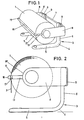
- Fig. 1 die erfindungsgemässe Vorrichtung in Perspektive,
- Fig. 2 eine Seitenansicht hierzu, gegen Fig. 1 etwas vergrössert,
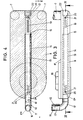
- Fig. 3 eine Draufsicht auf den einen Lagerarm im Massstab 1:1,
- Fig. 4 den Schnitt gemäss Linie IV-IV in Fig. 3,
- Fig. 5 die Vorderansicht der Vorrichtung,
- Fig. 6 einen Eckabschnitt des U-Bügels,
- Fig. 7 eine partielle Rückansicht der Schneidschiene und
- Fig. 8 die Stirnansicht hierzu.
- Die Vorrichtung zum Abziehen einer zur Rolle 1 aufgewickelten Bahn 2 aus Papier besitzt ein Gestell 3.
- Bestandteil dieses Gestelles 3 sind zwei winkeIförmig gestaltete Füsse 4, deren horizontaler Schenkel 5 die Vorderkante der vollständigen Rolle 1 noch etwas überragt und deren vertikaler, nach oben gerichteter Schenkel 6 an einer Verbindungsbrücke 7 des Gestelles 3 angreift. Die horizontale Verbindungsbrücke besteht aus zwei parallel zueinander verlaufenden, übereinander angeordneten Rohren, deren Stirnflächen gegen Backenartige Lagerarme 8 verspannt sind.
- Die Füsse 4 können auf der Verbindungsbrücke 7 in bezug aufeinander bzw. in bezug auf die Lagerarme 8 raumparallel zur Achsrichtung der Rolle 1 verstellt werden. Die jeweilige Abstandslage wird fixiert. Hierzu ist der nach oben gerichtete Schenkel 6 der Füsse 4 zu einer Klemmschelle ausgebildet, d.h. der genannte Schenkel 6 weist auf seiner Rückseite eine sickenartige Einlagerungsvertiefungen für die Rohre der Verbindungsbrücke 7 auf. Die entsprechende Gegenvertiefung befindet sich an je einer Schellenbacke 9, welche durch nicht näher dargestellte Schrauben gegen den Schenkel 6 verspannt wird, dies unter klemmender Festlegung an den Rohren.
- Die freiliegend horizontal vorstehenden Lagerarme 8 des Gestelles 3 weisen an ihrer Innenfläche 8' radial nach oben hin offene Lagermulden 10 für die Enden 11' des Wickelkerns 11 der Rolle 1 auf. Die Enden 11' können abgesetzt sein, so dass der Wickelkern im wesentlichen mit der gerundeten Stirnfläche 8" der Lagerarme 8 fluchtet bzw. dahinter zurückspringt, die Enden 11' dagegen wesentlich querschnittskleiner ausfallen.
- Dem Gestell 3 ist eine federnd gegen die Mantelfläche 1' der Rolle 1 anliegende Schneidschiene 12 zugeordnet. Letztere sitzt an in den Lagerarmen 8 des Gestelles 3 in radialer Richtung zur Rolle 1 längsverschieblichen Armen 13. Letztere sind horizontal ausgerichtet und schneiden die Längsmittelachse x-x des Wickelkerns 11. Bezüglich der Arme 13 ist auf Rohrmaterial runden Querschnitts zurückgegriffen. Zur Führung dient eine Längsbohrung 14, die im verbindungsbrückenseitigen Endbereich im Durchmesser reduziert ist, so dass eine Anschlagschulter 15 für das dortige Stirnende des Armes 13 vorliegt.
- Die beiden Arme 13 stehen über einen horizontalen Steg 16 miteinander in Verbindung. Arme 13 und Steg 16 bilden einen U-Bügel. Die Anbindung des aus einem Rohr gebildeten Stegs 16 an die Arme 13 erfolgt mittels Bogenstücken 17. Letztere weisen im Anschluss an die Bogenzone je einen Steckvorsprung 17' bzw. 17" auf. Die gegeneinander gerichteten Steckvorpsrünge 17' treten in die Enden des rohrförmigen Steges 16 ein, während die gegen das Stirnende (8") der Lagerarme 8 weisenden Steckvorsprünge 17" in die dortigen Enden der Arme eingeführt sind. Bezüglich der Vorsprünge 17' genügt eine lose Steckverbindung, da die Führung der Arme 13 die Stecklagersichert; im anderen Fall ist dagegen je eine Madenschraube 18 eingesetzt, die, eine Querbohrung des Armes 13 durchsetzend, in den Vorsprung 17" eintritt, der das entsprechende Gegengewinde besitzt.
- Die die Arme 13 zur Erzielung der Anlagebelastung der Schneidschiene einziehenden Zugfedern sind mit 19 bezeichnet. Sie erstrecken sich im rohrförmigen Arm 13 und sind beiderends fixiert. Dazu setzt sich einerseits der Steckvorsprung 17" in einen abgesetzten, zentralen Zapfen 20 fort, welcher eine Querbohrung 21 aufweist, in die das dortige, zu einem Haken gestaltete Ende der Feder eingreift. Die Lösbarkeit des Bogenstückes 17 ermöglicht eine bequeme Montage bzw. Demontage. Das andere, ebenfalls zu einem Haken gestaltete Federende ist an einem die entsprechende Querbohrung 21 aufweisenden, zentralen Zapfen 20 eines Schraubstopfens 22 gehalten.
- Die auf der der Rolle 1 zugekehrten Rückfläche des Steges 16 liegende Schneidschiene 12 endet etwa auf Höhe der unteren Scheitellinie 16 des Steges 16. Die Schneidschiene besitzt eine stumpfwinklige Querschnittsform. Der längere, an seiner unteren Schmalkante eine Sägezahnstruktur 23 bildende Schenkel erstreckt sich im wesentlichen vertikal, d.h. er ist leicht entgegen der Umfangsrundung der Rolle 1 abgestellt, so dass bei Rückdrehen der Rolle keine Beschädigung des Wickelgutes auftritt. Der kürzere Schenkel nimmt im wesentlichen einen die Rundung des Steges berücksichtigenden Verlauf. Dessen Schmahlkante endet noch unterhalb der oberen Scheitellinie 16" des Steges 16. Insgesamt liegt so eine zuordnungsgünstige Ausgestaltung vor, da der stumpfe Winkelinnenraum im Grunde zu einer selbstkorrigierenden Ausrichtung der Schneidschiene 12 führt. Sie ist einfach unter Zwischenlage eines Doppelklebebandes 24 hoher Haftkraft befestigt.
- Die in federnder Anlage gehaltene Schneidschiene wirkt zugleich als Bremse für die Rolle. Bei entsprechend grossem Wickelvorrat liegt zufolge der erhöhten Federspannung eine angepasst grössere Bremskraft vor als bei verringertem Vorrat bzw. Querschnitt. Die Ausgestaltung kann so vorgenommen sein, dass der Wickelrest nicht mehr gebremst ist, was, wie schon angedeutet, aber mit der Dicke des Wickelkerns zusammenhängt.
- Das Gestell 3 lässt sich auch als Wandkonsoleauch unter Tisch - benutzen, indem es in der aus der zeichnerischen Darstellung ersichtlichen Gebrauchsform an einer Wand angeschraubt wird. Der Schenkel 6 weist die dazu erforderlichen Bohrungen für Befestigungsmittel auf. Die Wandbefestigung kann auch über die Schellenbacke 9 erfolgen, indem diese an die Wand geschraubt wird; der Schenkel 6 könnte dann entfallen. Andererseits ist aber auch durch Nutzung der Schellenbacke 9 eine Hakenverbindung denkbar, indem der untere Schellenbackenbereich einfach hinterschnitten wird zum Eintritt des wandseitigen Hakenkopfes. Zufolge Zuordnung weiterer Füsse 4 lässt sich oberhalb der Rolle 1 eine Konsole bilden zum Aufstellen eines darüber anzuordnenden, weiteren Gestelles 3, bis zu einer Art Turmaufbau von noch weiteren Geräten. Auch könnte einer der Lagerarme 8- bei entsprechend breitflächiger Gestallt -, als Fuss für eine senkrechte Aufstellung dienen.
Claims (10)
Priority Applications (1)
| Application Number | Priority Date | Filing Date | Title |
|---|---|---|---|
| AT85102926T ATE27947T1 (de) | 1984-06-30 | 1985-03-14 | Abziehvorrichtung fuer eine rolle. |
Applications Claiming Priority (2)
| Application Number | Priority Date | Filing Date | Title |
|---|---|---|---|
| DE8419633U | 1984-06-30 | ||
| DE19848419633U DE8419633U1 (de) | 1984-06-30 | 1984-06-30 | Abziehvorrichtung |
Publications (2)
| Publication Number | Publication Date |
|---|---|
| EP0170768A1 EP0170768A1 (de) | 1986-02-12 |
| EP0170768B1 true EP0170768B1 (de) | 1987-06-24 |
Family
ID=6768379
Family Applications (1)
| Application Number | Title | Priority Date | Filing Date |
|---|---|---|---|
| EP85102926A Expired EP0170768B1 (de) | 1984-06-30 | 1985-03-14 | Abziehvorrichtung für eine Rolle |
Country Status (3)
| Country | Link |
|---|---|
| EP (1) | EP0170768B1 (de) |
| AT (1) | ATE27947T1 (de) |
| DE (2) | DE8419633U1 (de) |
Cited By (1)
| Publication number | Priority date | Publication date | Assignee | Title |
|---|---|---|---|---|
| DE202007016557U1 (de) | 2007-11-27 | 2009-04-02 | Hüdig und Rocholz GmbH & Co. KG | Abziehvorrichtung für einen Wickel einer Bahn |
Families Citing this family (6)
| Publication number | Priority date | Publication date | Assignee | Title |
|---|---|---|---|---|
| NZ225572A (en) * | 1987-07-29 | 1991-09-25 | First Green Park Pty Ltd | Rolled sheet material dispenser: surface engaging brake roller |
| FR2753694B1 (fr) * | 1996-09-20 | 1998-11-06 | Appareil de coupe et de distribution de produits conditionnes en rouleaux | |
| DE20301162U1 (de) * | 2003-01-22 | 2004-06-03 | Hüdig und Rocholz GmbH & Co. KG | Vorrichtung zum Abziehen einer zur Rolle aufgewickelten Bahn |
| MX366593B (es) | 2012-05-29 | 2019-07-15 | Gpcp Ip Holdings Llc | Dispensador de producto de hoja con porción móvil de carga. |
| CA2957106C (en) | 2014-08-08 | 2023-02-14 | Georgia-Pacific Consumer Products Lp | Sheet product dispensers and related methods for reducing sheet product usage |
| CN109230780A (zh) * | 2018-07-24 | 2019-01-18 | 芜湖金茂包装制品有限公司 | 一种纸制品包装用胶带截取装置 |
Family Cites Families (2)
| Publication number | Priority date | Publication date | Assignee | Title |
|---|---|---|---|---|
| DE3034256A1 (de) * | 1980-09-11 | 1982-04-15 | Apura GmbH + Co PWA Einmalhandtücher, 6200 Wiesbaden | Vorrichtung zur entnahme von abschnitten eines bahnfoermigen materials |
| DE3049323C2 (de) * | 1980-12-29 | 1984-11-22 | Feldmühle AG, 4000 Düsseldorf | Vorrichtung zum Abrollen und Trennen von Materialbahnen |
-
1984
- 1984-06-30 DE DE19848419633U patent/DE8419633U1/de not_active Expired
-
1985
- 1985-03-14 EP EP85102926A patent/EP0170768B1/de not_active Expired
- 1985-03-14 AT AT85102926T patent/ATE27947T1/de not_active IP Right Cessation
- 1985-03-14 DE DE8585102926T patent/DE3560282D1/de not_active Expired
Cited By (1)
| Publication number | Priority date | Publication date | Assignee | Title |
|---|---|---|---|---|
| DE202007016557U1 (de) | 2007-11-27 | 2009-04-02 | Hüdig und Rocholz GmbH & Co. KG | Abziehvorrichtung für einen Wickel einer Bahn |
Also Published As
| Publication number | Publication date |
|---|---|
| ATE27947T1 (de) | 1987-07-15 |
| DE3560282D1 (en) | 1987-07-30 |
| EP0170768A1 (de) | 1986-02-12 |
| DE8419633U1 (de) | 1984-09-27 |
Similar Documents
| Publication | Publication Date | Title |
|---|---|---|
| DE3636943C2 (de) | ||
| DE3525292C1 (de) | Kabeltrommelabroller | |
| EP0170768A1 (de) | Abziehvorrichtung für eine Rolle | |
| AT395458B (de) | Im bauwesen beim erstellen eines gebaeudes zu verwendende und an einer gebaeudewand im bereich einer herzustellenden decke zu befestigende vorrichtung zum halten eines umfangsseitigen schalbrettes einer deckenschalung | |
| EP0055422B1 (de) | Vorrichtung zum Abrollen und Trennen von Materialbahnen | |
| AT396382B (de) | In der hoehe variierbare aussparschalung fuer eine tueroeffnung od.dgl. ausnehmung in einer gebaeudewand | |
| DE8802658U1 (de) | Klemmhalter für die Befestigung der Tragstange eines Bettschleiers | |
| EP1004743A2 (de) | Senkrechtmarkise | |
| DE3121204C2 (de) | ||
| EP1727452A1 (de) | Leicht montierbarer papierbefeuchter | |
| DE2522885C2 (de) | Vorrichtung zur Staubbekämpfung in Streben mit mechanischer Kohlengewinnung im Untertagebergbau, mittels Düsen | |
| DE9420979U1 (de) | Dungförderer zur Stallentmistung | |
| DE952164C (de) | Vorrichtung zum Vorpfaenden von Stahlkappen fuer den Strebausbau | |
| DE20112914U1 (de) | Hilfsgerät zum Tapezieren | |
| DE29919446U1 (de) | Haltevorrichtung für eine Deckenrandschalung | |
| DE19908667A1 (de) | Gerät zum Kantenabkleben | |
| DE2004107C3 (de) | Deckelplatte aus Stahl zum Verschliessen einer im Sockelabschnitt eines Lichtmastes aus Stahlrohr angeordneten Montageoeffnung | |
| AT337945B (de) | Versetzbare trennwand | |
| AT385887B (de) | Fuehrung fuer ausziehbare moebelteile | |
| DE1429774C (de) | Halter fur Papierhandtuchrollen | |
| DE620498C (de) | Vorrichtung zum Verhueten des UEberschlagens von Rollvorhaengen | |
| DE1607349B1 (de) | Vorrichtung zur Entfernung von Huehnerkot an Kaefigreihen | |
| DE1753054C3 (de) | ||
| DE9115419U1 (de) | Leiterhalter | |
| CH400522A (de) | Wandkonsole, insbesondere für Fenstersimsen und dergleichen |
Legal Events
| Date | Code | Title | Description |
|---|---|---|---|
| PUAI | Public reference made under article 153(3) epc to a published international application that has entered the european phase |
Free format text: ORIGINAL CODE: 0009012 |
|
| AK | Designated contracting states |
Kind code of ref document: A1 Designated state(s): AT BE CH DE FR GB IT LI LU NL SE |
|
| 17P | Request for examination filed |
Effective date: 19860305 |
|
| 17Q | First examination report despatched |
Effective date: 19861014 |
|
| GRAA | (expected) grant |
Free format text: ORIGINAL CODE: 0009210 |
|
| AK | Designated contracting states |
Kind code of ref document: B1 Designated state(s): AT BE CH DE FR GB IT LI LU NL SE |
|
| REF | Corresponds to: |
Ref document number: 27947 Country of ref document: AT Date of ref document: 19870715 Kind code of ref document: T |
|
| REF | Corresponds to: |
Ref document number: 3560282 Country of ref document: DE Date of ref document: 19870730 |
|
| ET | Fr: translation filed | ||
| ITF | It: translation for a ep patent filed | ||
| PLBE | No opposition filed within time limit |
Free format text: ORIGINAL CODE: 0009261 |
|
| STAA | Information on the status of an ep patent application or granted ep patent |
Free format text: STATUS: NO OPPOSITION FILED WITHIN TIME LIMIT |
|
| 26N | No opposition filed | ||
| ITTA | It: last paid annual fee | ||
| PGFP | Annual fee paid to national office [announced via postgrant information from national office to epo] |
Ref country code: SE Payment date: 19920116 Year of fee payment: 8 |
|
| PGFP | Annual fee paid to national office [announced via postgrant information from national office to epo] |
Ref country code: LU Payment date: 19920122 Year of fee payment: 8 |
|
| PGFP | Annual fee paid to national office [announced via postgrant information from national office to epo] |
Ref country code: FR Payment date: 19920124 Year of fee payment: 8 |
|
| PGFP | Annual fee paid to national office [announced via postgrant information from national office to epo] |
Ref country code: AT Payment date: 19920220 Year of fee payment: 8 |
|
| PGFP | Annual fee paid to national office [announced via postgrant information from national office to epo] |
Ref country code: GB Payment date: 19920303 Year of fee payment: 8 |
|
| EPTA | Lu: last paid annual fee | ||
| PG25 | Lapsed in a contracting state [announced via postgrant information from national office to epo] |
Ref country code: LU Free format text: LAPSE BECAUSE OF NON-PAYMENT OF DUE FEES Effective date: 19930314 Ref country code: GB Effective date: 19930314 Ref country code: AT Effective date: 19930314 |
|
| PG25 | Lapsed in a contracting state [announced via postgrant information from national office to epo] |
Ref country code: SE Effective date: 19930315 |
|
| GBPC | Gb: european patent ceased through non-payment of renewal fee |
Effective date: 19930314 |
|
| PG25 | Lapsed in a contracting state [announced via postgrant information from national office to epo] |
Ref country code: FR Effective date: 19931130 |
|
| REG | Reference to a national code |
Ref country code: FR Ref legal event code: ST |
|
| EUG | Se: european patent has lapsed |
Ref document number: 85102926.4 Effective date: 19931008 |
|
| PGFP | Annual fee paid to national office [announced via postgrant information from national office to epo] |
Ref country code: DE Payment date: 20031229 Year of fee payment: 20 |
|
| PGFP | Annual fee paid to national office [announced via postgrant information from national office to epo] |
Ref country code: NL Payment date: 20040204 Year of fee payment: 20 |
|
| PGFP | Annual fee paid to national office [announced via postgrant information from national office to epo] |
Ref country code: CH Payment date: 20040206 Year of fee payment: 20 |
|
| PGFP | Annual fee paid to national office [announced via postgrant information from national office to epo] |
Ref country code: BE Payment date: 20040209 Year of fee payment: 20 |
|
| PG25 | Lapsed in a contracting state [announced via postgrant information from national office to epo] |
Ref country code: LI Free format text: LAPSE BECAUSE OF EXPIRATION OF PROTECTION Effective date: 20050313 Ref country code: CH Free format text: LAPSE BECAUSE OF EXPIRATION OF PROTECTION Effective date: 20050313 |
|
| PG25 | Lapsed in a contracting state [announced via postgrant information from national office to epo] |
Ref country code: NL Free format text: LAPSE BECAUSE OF EXPIRATION OF PROTECTION Effective date: 20050314 |
|
| BE20 | Be: patent expired |
Owner name: *HUDIG UND ROCHOLZ G.M.B.H. & CO. K.G. Effective date: 20050314 |
|
| REG | Reference to a national code |
Ref country code: CH Ref legal event code: PL |
|
| NLV7 | Nl: ceased due to reaching the maximum lifetime of a patent |
Effective date: 20050314 |
|
| BE20 | Be: patent expired |
Owner name: *HUDIG UND ROCHOLZ G.M.B.H. & CO. K.G. Effective date: 20050314 |