EP0170018B1 - Procédé et dispositif d'autodiagnostic d'organes de réglage - Google Patents
Procédé et dispositif d'autodiagnostic d'organes de réglage Download PDFInfo
- Publication number
- EP0170018B1 EP0170018B1 EP19850107387 EP85107387A EP0170018B1 EP 0170018 B1 EP0170018 B1 EP 0170018B1 EP 19850107387 EP19850107387 EP 19850107387 EP 85107387 A EP85107387 A EP 85107387A EP 0170018 B1 EP0170018 B1 EP 0170018B1
- Authority
- EP
- European Patent Office
- Prior art keywords
- actuator
- control
- internal combustion
- combustion engine
- signal
- Prior art date
- Legal status (The legal status is an assumption and is not a legal conclusion. Google has not performed a legal analysis and makes no representation as to the accuracy of the status listed.)
- Expired - Lifetime
Links
Images
Classifications
-
- F—MECHANICAL ENGINEERING; LIGHTING; HEATING; WEAPONS; BLASTING
- F02—COMBUSTION ENGINES; HOT-GAS OR COMBUSTION-PRODUCT ENGINE PLANTS
- F02D—CONTROLLING COMBUSTION ENGINES
- F02D41/00—Electrical control of supply of combustible mixture or its constituents
- F02D41/02—Circuit arrangements for generating control signals
- F02D41/18—Circuit arrangements for generating control signals by measuring intake air flow
-
- F—MECHANICAL ENGINEERING; LIGHTING; HEATING; WEAPONS; BLASTING
- F02—COMBUSTION ENGINES; HOT-GAS OR COMBUSTION-PRODUCT ENGINE PLANTS
- F02D—CONTROLLING COMBUSTION ENGINES
- F02D31/00—Use of speed-sensing governors to control combustion engines, not otherwise provided for
- F02D31/001—Electric control of rotation speed
- F02D31/002—Electric control of rotation speed controlling air supply
- F02D31/003—Electric control of rotation speed controlling air supply for idle speed control
- F02D31/005—Electric control of rotation speed controlling air supply for idle speed control by controlling a throttle by-pass
-
- F—MECHANICAL ENGINEERING; LIGHTING; HEATING; WEAPONS; BLASTING
- F02—COMBUSTION ENGINES; HOT-GAS OR COMBUSTION-PRODUCT ENGINE PLANTS
- F02D—CONTROLLING COMBUSTION ENGINES
- F02D41/00—Electrical control of supply of combustible mixture or its constituents
- F02D41/22—Safety or indicating devices for abnormal conditions
- F02D41/221—Safety or indicating devices for abnormal conditions relating to the failure of actuators or electrically driven elements
-
- F—MECHANICAL ENGINEERING; LIGHTING; HEATING; WEAPONS; BLASTING
- F02—COMBUSTION ENGINES; HOT-GAS OR COMBUSTION-PRODUCT ENGINE PLANTS
- F02D—CONTROLLING COMBUSTION ENGINES
- F02D2200/00—Input parameters for engine control
- F02D2200/02—Input parameters for engine control the parameters being related to the engine
- F02D2200/04—Engine intake system parameters
- F02D2200/0406—Intake manifold pressure
-
- Y—GENERAL TAGGING OF NEW TECHNOLOGICAL DEVELOPMENTS; GENERAL TAGGING OF CROSS-SECTIONAL TECHNOLOGIES SPANNING OVER SEVERAL SECTIONS OF THE IPC; TECHNICAL SUBJECTS COVERED BY FORMER USPC CROSS-REFERENCE ART COLLECTIONS [XRACs] AND DIGESTS
- Y02—TECHNOLOGIES OR APPLICATIONS FOR MITIGATION OR ADAPTATION AGAINST CLIMATE CHANGE
- Y02T—CLIMATE CHANGE MITIGATION TECHNOLOGIES RELATED TO TRANSPORTATION
- Y02T10/00—Road transport of goods or passengers
- Y02T10/10—Internal combustion engine [ICE] based vehicles
- Y02T10/40—Engine management systems
Definitions
- the invention is based on a method and a device according to the type of the main claim and the first device claim.
- a variable which is usually electrical and has a specific function profile
- a controller which processes certain input signals from the controlled system assigned to it and dash incorporates the result achieved by its actuator adjustment into its actuation behavior, namely by evaluating corresponding actual value variables measured by it.
- US-A-4 414 950 From US-A-4 414 950 it is known to carry out the functionality of a sensor by means of a plausibility check of the output signal of this sensor on the basis of another sensor signal, this other sensor signal relating to another operating parameter and being processed for another control or regulating task. It is proposed in US-A-4 414 950 to check the functionality of a speed sensor by comparing the speed signal for a given operating point with the output signal of a pressure gauge in the intake manifold of the internal combustion engine and determining the functionality of the speed sensor when between Speed value and intake pressure value a predetermined relationship is met.
- a problem is, however, a diagnosis of the actuator itself, which could be carried out without reactions occurring in the control path assigned to or controlled by this actuator, which are not desired and without it being necessary to shut down the system or to move the actuator the assignment of additional hardware components that are then required to be recorded and evaluated in the sense of a diagnosis.
- the measure can be regarded as simply performing an actuator diagnosis with the system shut down by actuating the respective actuator, for example by supplying an externally generated signal, and then simply the actuator reaction visually or where this is not possible , for example by feeling or by means of a hearing test.
- JP-A-57-186038 it is known from JP-A-57-186038 to recognize an error state of the actuator of the idle system when the idle switch is actuated by checking the current speed signal value by means of a logic device.
- n; L7as the method according to the invention with the characterizing features of the main claim or the device according to the invention with the characterizing features of the first device claim have the advantage that self-diagnosis of actuators including their mechanical function is possible without any additional effort, no additional hardware components being required and Depending on the training and integration of the systems involved, the diagnosis can also be carried out at least in part by running a program and comparing measured and stored values at specific time intervals, if necessary by the same microprocessors or small computers that are responsible for the actual control of the control element in the control system.
- the invention is designed so that it is the result of a self-diagnosis Control of the actuator is detected at least indirectly, using an actual value, which is prepared for other control purposes anyway by suitable actual value transmitters and supplied to the overall system.
- a self-diagnosis of the actuator of an idle charge control when operating an internal combustion engine this means that a pressure measurement or air volume or air mass measurement in the intake manifold of the internal combustion engine, also as a function, is evaluated as the actual value for the reaction of the LFR actuator to be checked, the control, for which the LFR actuator forms a sub-component, does not need any information relating to air values, but uses a speed variable as the actual value.
- the invention is able to check not only a certain working point of the actuator for proper function, but to run the entire actuator variation, to detect mechanical damage, such as jamming of the actuator, and at the same time to loose contacts or other faults in the actuator circuit to capture.
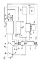
- FIG. 1 shows schematically a possible exemplary embodiment of a circuit for self-diagnosis of actuators using discrete components of a block diagram
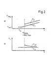
- FIG. 2 shows curves of the actuator opening as a percentage of an idle charge control and related load signals, in each case above the speed when an internal combustion engine is in overrun.
- the basic idea of the present invention is to control the actuator of a specific control system in the case of combined regulating or control systems, specifically in those operating states in which the controlled system controlled by this regulating system shows no or almost no reactions to the actuator change, that is to say no corresponding changes ( undesirable) effects and insofar as there is no influence on the actual value of this control system, but in doing so evaluate the sinal of another actual value that belongs to another control system but is correlated with the size controlled by the relevant actuator.
- the description given below of the preferred exemplary embodiment of the invention is therefore to be evaluated with regard to the overall functional and time sequence, the mode of operation achieved by the blocks discussed in each case and with regard to the respective interaction of the subfunction (s) represented by the individual components, the references to the individual circuit blocks facilitate understanding of the present invention.
- the invention relates to the application example of a self-diagnosis of the idle charge control actuator (LFR actuator) when operating an internal combustion engine, which is therefore only discussed in detail below.
- LFR actuator idle charge control actuator
- the basic principle of such an idle charge control is that the controller 10 of the idle charge control has certain input signals relating to a speed setpoint, the speed actual value, the temperature of the internal combustion engine and the like. are supplied and this, without going into too much detail, supplies its downstream output stage 12 with a signal so that it can control the actual actuator, which is designed, for example, as a so-called two-winding rotary actuator, such that one belonging to the two-winding rotary actuator 13 Valve 13a, for example in an air bypass line 14 to intake pipe 15 with throttle valve 16 essentially closed (idling), controls the amount of air to be supplied to internal combustion engine 17 in such a way that the actual speed n, st , can be disregarded within predetermined limits. It is understood that such an embodiment of an idle charge regulator is only one of the possible embodiments.
- the combined system of controlled control and regulation of an internal combustion engine 17 further includes, in addition to the integrated idle charge control, an electrical or electronic injection control and / or ignition control, and possibly further control systems, including load detection via a pressure measurement or an air quantity or air mass measurement in the intake manifold 15.
- Such an air flow sensor is indicated in FIG. 1 by 18 and can schematically comprise a mechanically pivotable baffle flap 18a, the pivoting angle of which is a measure of that via the intake pipe of the internal combustion engine amount of air supplied is Q.
- the injection controller 20 uses, inter alia, this load signal Q and a speed list signal n ist and generates injection commands at its output which are fed to fuel injection valves 21.
- the injection controller 20 can also process a large number of other input signals and operating state signals which are fed to it and which are indicated overall by the arrow A in FIG. 1.
- the invention comes into play, in which the operating states of the internal combustion engine are first selected, in which the driver naturally does not actuate the accelerator pedal in normal operation of the motor vehicle, i.e. with the internal combustion engine running and without the function or the system being switched off, and in which an operation is also carried out changed control of the LFR actuator to change the amount of additional air it produces does not result in any unpleasant or unexpected effects on driving or engine behavior.
- a change in the actuator opening is carried out based on the normal LFR actuator value, namely by means of a correspondingly different control signal, and the change in the air quantity or mass or the measured intake manifold pressure, which is determined by this change, is checked.
- the changed actuator control can be carried out by influencing the LFR controller or its output stage 12 accordingly, or that the LFR actuator is supplied with a separate control signal via a connecting line 22 from a discrete diagnostic circuit 23. It should be emphasized again that this diagnostic circuit can also be part of the program flow of the microcomputer, for example the IlC-controlled Motronic / L-Jetronic systems.
- the operating states which are suitable for the diagnostic control of the LFR actuator are preferably sliding operating states of the internal combustion engine with overrun cutoff above a predetermined speed threshold (for example n> 1800 min- 1 ). If the actuator is opened further above this speed threshold, it can be checked at the same time whether this changes the load signal measured by the encoder 18, by setting up a possible drop in speed. Such an actuator control is otherwise not noticeable in driving behavior, since the fuel cut-off means that the injection is interrupted anyway and therefore only the air throughput through the intake manifold 15 and the internal combustion engine 17 changes.
- a predetermined speed threshold for example n> 1800 min- 1
- a load signal results for a normal, predetermined actuator opening T , depending on the rotational speed in the push mode, corresponding to the curve a in FIG. 2
- this load signal must have the value tL2 in Fig. 2 in accordance with the curve of the load signal versus the speed at b) in FIG. 2 enlarge.
- These data resulting from the diagram profiles in FIG. 2 can be part of an additional memory 24 for the diagnostic circuit 23, or are stored at a suitable location in the memory means of the microcomputers or microprocessors forming the control systems, so that it is possible for a GUT- Evaluation required correlation between diagnostic control of the actuator and the assigned load signal from the stored data.
- the special exemplary embodiment in FIG. 1 also has a fuel cut-off detection block 25 or a post-start detection block 25 ', which will be discussed in a moment.
- the diagnostic circuit 23 is preferably also supplied with an actual value signal of the rotational speed, which is also present during the operation of an internal combustion engine and is supplied, for example, by an encoder 26 in a suitable manner , for example inductively or capacitively, scans certain markings 27a on a crankshaft-synchronously rotating disk 27.
- an LFR actuator check to use the post-start according to block 25 'in FIG. 1 as a suitable operating state .
- an increased idle speed is initially set when the actuator opening is initiated by the LFR controller itself. Then the associated large amount of air is reduced by closing the actuator until the desired idle speed is reached.
- the variation of the air volume from the transmitter 18 as a result and correlated with the change in the actuator opening can also be checked for plausibility in the diagnostic circuit 23.
- the diagnosis process is also initiated by a suitable post-start signal; However, it is not the diagnostic circuit 23 which then controls the LFR actuator, but rather the control signal for the LFR actuator is fed to the latter and, in parallel, the diagnostic circuit 23 or corresponding areas in the microcomputer which, when the restart signal is present, simultaneously receives the load signal from another control loop is used as the actual value and compares the values and / or function curves supplied and / or measured to it with the stored assignments.
Claims (8)
Applications Claiming Priority (4)
| Application Number | Priority Date | Filing Date | Title |
|---|---|---|---|
| DE3428620 | 1984-08-03 | ||
| DE3428620 | 1984-08-03 | ||
| DE19843435465 DE3435465A1 (de) | 1984-08-03 | 1984-09-27 | Verfahren und vorrichtung zur eigendiagnose von stellgliedern |
| DE3435465 | 1984-09-27 |
Publications (3)
| Publication Number | Publication Date |
|---|---|
| EP0170018A2 EP0170018A2 (fr) | 1986-02-05 |
| EP0170018A3 EP0170018A3 (en) | 1988-03-23 |
| EP0170018B1 true EP0170018B1 (fr) | 1990-10-03 |
Family
ID=25823538
Family Applications (1)
| Application Number | Title | Priority Date | Filing Date |
|---|---|---|---|
| EP19850107387 Expired - Lifetime EP0170018B1 (fr) | 1984-08-03 | 1985-06-14 | Procédé et dispositif d'autodiagnostic d'organes de réglage |
Country Status (5)
| Country | Link |
|---|---|
| US (1) | US4601199A (fr) |
| EP (1) | EP0170018B1 (fr) |
| JP (1) | JPH065197B2 (fr) |
| BR (1) | BR8503654A (fr) |
| DE (2) | DE3435465A1 (fr) |
Cited By (2)
| Publication number | Priority date | Publication date | Assignee | Title |
|---|---|---|---|---|
| DE4229774C2 (de) * | 1992-09-05 | 2002-06-20 | Bosch Gmbh Robert | Vorrichtung zur Steuerung einer Brennkraftmaschine |
| DE19707868B4 (de) * | 1997-02-27 | 2008-10-30 | Robert Bosch Gmbh | Verfahren und Vorrichtung zur Überwachung eines Systems zur Steuerung einer Brennkraftmaschine |
Families Citing this family (38)
| Publication number | Priority date | Publication date | Assignee | Title |
|---|---|---|---|---|
| JPS62649A (ja) * | 1985-06-25 | 1987-01-06 | Honda Motor Co Ltd | 内燃エンジン用制御装置の出力タイミング異常検出方法 |
| JPH0663471B2 (ja) * | 1986-02-13 | 1994-08-22 | 本田技研工業株式会社 | 内燃機関の補助空気量制御装置 |
| US4943924A (en) * | 1986-06-27 | 1990-07-24 | Nissan Motor Company, Limited | Trouble checking apparatus |
| DE3624441A1 (de) * | 1986-07-19 | 1988-01-28 | Bosch Gmbh Robert | Diagnoseverfahren zur quantitativen ueberpruefung von stellgliedern bei brennkraftmaschinen |
| JPS6388248A (ja) * | 1986-10-01 | 1988-04-19 | Toyota Motor Corp | 排気ガス浄化装置の故障診断装置 |
| DE3730513A1 (de) * | 1987-09-11 | 1989-03-23 | Triumph Adler Ag | Schaltungsanordnung fuer eine vorrichtung zur leerlauffuellungsregelung bei brennkraftmaschinen |
| DE3802771A1 (de) * | 1988-01-30 | 1989-08-10 | Bosch Gmbh Robert | Sicherheitssystem fuer brennkraftmaschinen |
| DE3803078C2 (de) * | 1988-02-03 | 2000-11-02 | Bosch Gmbh Robert | Verfahren und Einrichtung zur Positionsüberwachung eines elektrischen Ist-Positionsgebers |
| DE3808382A1 (de) * | 1988-03-12 | 1989-09-21 | Bosch Gmbh Robert | Verfahren und vorrichtung zur ueberwachung eines sicherheitsabstellers bei brennkraftmaschinen |
| DE3808381C2 (de) * | 1988-03-12 | 1996-07-11 | Bosch Gmbh Robert | Verfahren und Vorrichtung zur Überwachung eines Sicherheitsabstellers bei Brennkraftmaschinen |
| JPH0623736Y2 (ja) * | 1988-08-10 | 1994-06-22 | トヨタ自動車株式会社 | 内燃機関のエバポパージ異常検出装置 |
| DE3828932A1 (de) * | 1988-08-26 | 1990-03-01 | Teves Gmbh Alfred | Verfahren zur ueberwachung des betriebs einer hydraulischen, pneumatischen, mechanischen und/oder elektrischen vorrichtung |
| JPH02105034A (ja) * | 1988-10-14 | 1990-04-17 | Mitsubishi Electric Corp | 故障診断装置 |
| US4875456A (en) * | 1989-02-08 | 1989-10-24 | Japan Electronic Control Systems Company Limited | Self-diagnosis system for auxiliary air control system of internal combustion engine |
| DE3914536C2 (de) * | 1989-05-02 | 1998-05-14 | Bosch Gmbh Robert | Verfahren und Vorrichtung zur Diagnose von Stellgliedern bei der Regelung und/oder Steuerung von Betriebsparametern in Verbindung der Leerlaufregelung und der Tankentlüftung bei Brennkraftmaschinen |
| US4974444A (en) * | 1989-07-05 | 1990-12-04 | Ford Motor Company | Electronically controlled engine throttle plate adjustment |
| DE3925881A1 (de) * | 1989-08-04 | 1991-02-07 | Bosch Gmbh Robert | Verfahren und vorrichtung zur steuerung und/oder regelung der motorleistung einer brennkraftmaschine eines kraftfahrzeugs |
| DE3942836A1 (de) * | 1989-12-23 | 1991-06-27 | Daimler Benz Ag | Verfahren zur bewegungs- und lagezustandserkennung eines durch magnetische wechselwirkung zwischen zwei endpositionen beweglichen bauteiles eines induktiven elektrischen verbrauchers |
| DE4005973A1 (de) * | 1990-02-26 | 1991-09-05 | Bosch Gmbh Robert | Diagnoseverfahren zur ueberpruefung von stellgliedern zur steuerung von brennkraftmaschinen |
| JPH041451A (ja) * | 1990-04-17 | 1992-01-06 | Mitsubishi Electric Corp | エンジンの故障診断装置 |
| DE4024036A1 (de) * | 1990-07-28 | 1992-01-30 | Audi Ag | Verfahren zum betrieb einer brennkraftmaschine |
| DE4130846A1 (de) * | 1991-09-17 | 1993-03-18 | Egm Entwicklung Montage | Verfahren zum pruefen von komponenten fuer verbrennungsmotoren |
| DE4220286C2 (de) * | 1992-06-20 | 2001-08-09 | Bosch Gmbh Robert | Verfahren zur Funktionsüberprüfung eines Stellelements in einem Fahrzeug |
| JPH07119559A (ja) * | 1993-10-26 | 1995-05-09 | Mitsubishi Electric Corp | 内燃機関の制御装置 |
| JPH07311620A (ja) * | 1994-05-17 | 1995-11-28 | Nec Corp | 制御用コンピュータのための故障検出装置 |
| DE4419548B4 (de) * | 1994-06-03 | 2004-02-19 | Samson Ag | Verfahren zur Überwachung der Funktionsfähigkeit eines pneumatischen Stellgerätes |
| BR9509446A (pt) * | 1994-10-26 | 1997-12-23 | Siemens Ag | Processo para a análise de um valor medido como também de um analisador de valor medido para a execução do processo |
| DE19643297C1 (de) * | 1996-10-21 | 1998-03-12 | Samson Ag | Verfahren und Vorrichtung zur Überwachung von Stellgeräten |
| DE19650828B4 (de) * | 1996-12-07 | 2005-09-29 | Robert Bosch Gmbh | Prüfgerät zur Überprüfung eines Steuergeräts |
| DE19923296A1 (de) * | 1999-05-21 | 2000-12-07 | Baelz Gmbh Helmut | Anlage mit Prüfeinrichtung |
| DE10001583C2 (de) * | 2000-01-17 | 2002-03-21 | Bosch Gmbh Robert | Verfahren und Einrichtung zur Funktionsüberwachung eines Gasströmungssteuerorgans, insbesondere einer Drallkappe, bei einer Brennkraftmaschine |
| DE10039952C2 (de) | 2000-08-16 | 2003-04-24 | Siemens Ag | Verfahren zur Überprüfung einer Abgasrückführanlage |
| DE10053334B4 (de) | 2000-10-27 | 2018-08-02 | Robert Bosch Gmbh | Verfahren und Vorrichtung zur Steuerung eines Stellelements in einem Fahrzeug |
| DE10145906A1 (de) * | 2001-09-18 | 2003-04-10 | Bosch Gmbh Robert | Verfahren zur Durchfühung einer Ferndiagnose bei einem Kraftfahrzeug, Fahrzeugdiagnosemodul und Servicecenter |
| DE10320031A1 (de) * | 2003-05-06 | 2004-12-16 | Samson Ag | Verfahren und Vorrichtung zum Prüfen der Betriebssicherheit eines Prozessstellgeräts |
| DE102004039138B4 (de) * | 2004-08-12 | 2009-02-19 | Bosch Rexroth Pneumatics Gmbh | Ventileinheit |
| DE102006010542B3 (de) | 2006-03-07 | 2007-08-23 | Siemens Ag | Verfahren zum Erkennen einer fehlerhaften Stelleinrichtung |
| JP5144169B2 (ja) * | 2007-08-17 | 2013-02-13 | 本田技研工業株式会社 | コージェネレーション装置 |
Citations (1)
| Publication number | Priority date | Publication date | Assignee | Title |
|---|---|---|---|---|
| JPS57186038A (en) * | 1981-05-11 | 1982-11-16 | Automob Antipollut & Saf Res Center | Idle speed controller |
Family Cites Families (10)
| Publication number | Priority date | Publication date | Assignee | Title |
|---|---|---|---|---|
| IT1081383B (it) * | 1977-04-27 | 1985-05-21 | Magneti Marelli Spa | Apparecchiatura elettronica per il controllo dell'alimentazione di una miscela aria/benzina di un motore a combustione interna |
| DE2846804C2 (de) * | 1978-10-27 | 1982-08-12 | Volkswagenwerk Ag, 3180 Wolfsburg | Verfahren und Anordnung zur Erzielung einer Korrektur einer Kennlinie, die in einer Ansteuereinrichtung für ein Kraftstoffzumeßorgan einer Brennkraftmaschine gespeichert ist |
| JPS5596339A (en) * | 1979-01-13 | 1980-07-22 | Nippon Denso Co Ltd | Air-fuel ratio control method |
| JPS55126841A (en) * | 1979-03-23 | 1980-10-01 | Nissan Motor Co Ltd | Diagnosing method of controller for motorcar |
| DE2935585C2 (de) * | 1979-09-04 | 1982-04-08 | Dürkoppwerke GmbH, 4800 Bielefeld | Schaltungsanordnung zur mit Gleichspannung durchführbaren Durchgangsprüfung |
| JPS5770931A (en) * | 1980-10-06 | 1982-05-01 | Honda Motor Co Ltd | Trouble backup device for air fuel ratio feddback controller of internal combustion engine |
| DE3128245A1 (de) * | 1981-07-17 | 1983-01-27 | Dr.Ing.H.C. F. Porsche Ag, 7000 Stuttgart | "verfahren zur steuerung des verbrennungsablaufs in brennkraftmaschinen" |
| DE3211644A1 (de) * | 1982-03-30 | 1983-10-13 | Daimler-Benz Ag, 7000 Stuttgart | Vorrichtung zur ausfallerkennung eines sensors |
| JPS595310A (ja) * | 1982-07-02 | 1984-01-12 | Nissan Motor Co Ltd | 車両故障診断装置 |
| JPS5925056A (ja) * | 1982-08-03 | 1984-02-08 | Toyota Motor Corp | 内燃機関のアイドル回転速度制御弁の異常検出方法 |
-
1984
- 1984-09-27 DE DE19843435465 patent/DE3435465A1/de not_active Withdrawn
-
1985
- 1985-06-14 DE DE8585107387T patent/DE3579972D1/de not_active Expired - Lifetime
- 1985-06-14 EP EP19850107387 patent/EP0170018B1/fr not_active Expired - Lifetime
- 1985-07-11 US US06/754,514 patent/US4601199A/en not_active Expired - Lifetime
- 1985-07-24 JP JP60162193A patent/JPH065197B2/ja not_active Expired - Lifetime
- 1985-08-02 BR BR8503654A patent/BR8503654A/pt not_active IP Right Cessation
Patent Citations (1)
| Publication number | Priority date | Publication date | Assignee | Title |
|---|---|---|---|---|
| JPS57186038A (en) * | 1981-05-11 | 1982-11-16 | Automob Antipollut & Saf Res Center | Idle speed controller |
Cited By (2)
| Publication number | Priority date | Publication date | Assignee | Title |
|---|---|---|---|---|
| DE4229774C2 (de) * | 1992-09-05 | 2002-06-20 | Bosch Gmbh Robert | Vorrichtung zur Steuerung einer Brennkraftmaschine |
| DE19707868B4 (de) * | 1997-02-27 | 2008-10-30 | Robert Bosch Gmbh | Verfahren und Vorrichtung zur Überwachung eines Systems zur Steuerung einer Brennkraftmaschine |
Also Published As
| Publication number | Publication date |
|---|---|
| JPH065197B2 (ja) | 1994-01-19 |
| DE3579972D1 (de) | 1990-11-08 |
| EP0170018A3 (en) | 1988-03-23 |
| DE3435465A1 (de) | 1986-02-13 |
| EP0170018A2 (fr) | 1986-02-05 |
| JPS6145950A (ja) | 1986-03-06 |
| US4601199A (en) | 1986-07-22 |
| BR8503654A (pt) | 1986-05-06 |
Similar Documents
| Publication | Publication Date | Title |
|---|---|---|
| EP0170018B1 (fr) | Procédé et dispositif d'autodiagnostic d'organes de réglage | |
| DE3624441C2 (fr) | ||
| EP0470960B1 (fr) | Procede et dispositif de controle de la manoeuvrabilite de la soupape d'aeration d'un reservoir | |
| DE102008001569B4 (de) | Verfahren und Vorrichtung zur Adaption eines Dynamikmodells einer Abgassonde | |
| DE3914536C2 (de) | Verfahren und Vorrichtung zur Diagnose von Stellgliedern bei der Regelung und/oder Steuerung von Betriebsparametern in Verbindung der Leerlaufregelung und der Tankentlüftung bei Brennkraftmaschinen | |
| DE10230899B4 (de) | Verfahren zum Diagnostizieren einer fehlerhaften Ventilhubstellung einer Brennkraftmaschine | |
| EP0437559B1 (fr) | Procede et dispositif de commande et/ou de regulation de la puissance du moteur a combustion interne d'un vehicule | |
| DE4302483C2 (de) | Verfahren und Vorrichtung zur Steuerung einer Brennkraftmaschine | |
| EP1222378A1 (fr) | Dispositif et procede pour commander une unite d'entrainement | |
| WO2000063546A1 (fr) | Procede et dispositif pour le controle d'un calculateur dans un vehicule | |
| WO2009095333A1 (fr) | Procédé pour la commande d'un moteur à combustion interne | |
| EP1309781B1 (fr) | Procede et dispositif de commande d'un moteur thermique | |
| WO1991005155A1 (fr) | Procede et dispositif de commande d'arrivee d'air dans un moteur a combustion interne | |
| DE4208133C2 (de) | Fehlerdiagnoseeinrichtung für eine Abgasrückführungssteuereinheit | |
| DE102015210226B4 (de) | Verfahren und Vorrichtung zur Erhöhung der Leistung eines Verbrennungsmotors durch Nutzung eines Turboladerdrehzahlmodells und eines Turboladerdrehzahlsensors | |
| EP0708233B1 (fr) | Procédé et dispositif pour commander un moteur à combustion interne | |
| DE4341434C1 (de) | Verfahren und Vorrichtung zur Funktionsüberprüfung einer Brennkraftmaschine | |
| DE4220286C2 (de) | Verfahren zur Funktionsüberprüfung eines Stellelements in einem Fahrzeug | |
| DE3235497C2 (fr) | ||
| DE102012200032A1 (de) | Verfahren und Vorrichtung zur Dynamik-Diagnose von Sensoren | |
| DE19741086B4 (de) | Verfahren und Vorrichtung zur Überwachung der Einstellung eines Stellelements | |
| WO2010081607A1 (fr) | Procédé d'exécution d'un certain nombre d'injections | |
| WO2007017358A1 (fr) | Dispositif de commande et element pour vehicule automobile | |
| EP1243778B1 (fr) | Procédé de diagnostic du fonctionnement d'au moins un élément d'agitation de la charge par évaluation des irrégularités de régime | |
| DE4222693C2 (de) | Elektronische Motorsteuerung mit einer Anreicherungsfunktion |
Legal Events
| Date | Code | Title | Description |
|---|---|---|---|
| PUAI | Public reference made under article 153(3) epc to a published international application that has entered the european phase |
Free format text: ORIGINAL CODE: 0009012 |
|
| AK | Designated contracting states |
Designated state(s): DE FR GB |
|
| PUAL | Search report despatched |
Free format text: ORIGINAL CODE: 0009013 |
|
| AK | Designated contracting states |
Kind code of ref document: A3 Designated state(s): DE FR GB |
|
| 17P | Request for examination filed |
Effective date: 19880923 |
|
| 17Q | First examination report despatched |
Effective date: 19890208 |
|
| GRAA | (expected) grant |
Free format text: ORIGINAL CODE: 0009210 |
|
| AK | Designated contracting states |
Kind code of ref document: B1 Designated state(s): DE FR GB |
|
| ET | Fr: translation filed | ||
| GBT | Gb: translation of ep patent filed (gb section 77(6)(a)/1977) | ||
| REF | Corresponds to: |
Ref document number: 3579972 Country of ref document: DE Date of ref document: 19901108 |
|
| PLBI | Opposition filed |
Free format text: ORIGINAL CODE: 0009260 |
|
| 26 | Opposition filed |
Opponent name: SIEMENS AKTIENGESELLSCHAFT, BERLIN UND MUENCHEN Effective date: 19910703 |
|
| RAP4 | Party data changed (patent owner data changed or rights of a patent transferred) |
Owner name: ROBERT BOSCH GMBH |
|
| PLBN | Opposition rejected |
Free format text: ORIGINAL CODE: 0009273 |
|
| STAA | Information on the status of an ep patent application or granted ep patent |
Free format text: STATUS: OPPOSITION REJECTED |
|
| 27O | Opposition rejected |
Effective date: 19920623 |
|
| PGFP | Annual fee paid to national office [announced via postgrant information from national office to epo] |
Ref country code: GB Payment date: 19960531 Year of fee payment: 12 |
|
| PG25 | Lapsed in a contracting state [announced via postgrant information from national office to epo] |
Ref country code: GB Free format text: LAPSE BECAUSE OF NON-PAYMENT OF DUE FEES Effective date: 19970614 |
|
| REG | Reference to a national code |
Ref country code: FR Ref legal event code: D6 |
|
| GBPC | Gb: european patent ceased through non-payment of renewal fee |
Effective date: 19970614 |
|
| PGFP | Annual fee paid to national office [announced via postgrant information from national office to epo] |
Ref country code: DE Payment date: 19991230 Year of fee payment: 16 |
|
| PGFP | Annual fee paid to national office [announced via postgrant information from national office to epo] |
Ref country code: FR Payment date: 20000621 Year of fee payment: 16 |
|
| PG25 | Lapsed in a contracting state [announced via postgrant information from national office to epo] |
Ref country code: FR Free format text: LAPSE BECAUSE OF NON-PAYMENT OF DUE FEES Effective date: 20020228 |
|
| PG25 | Lapsed in a contracting state [announced via postgrant information from national office to epo] |
Ref country code: DE Free format text: LAPSE BECAUSE OF NON-PAYMENT OF DUE FEES Effective date: 20020403 |
|
| APAH | Appeal reference modified |
Free format text: ORIGINAL CODE: EPIDOSCREFNO |