EP0170018B1 - Process and apparatus for the self-testing of control levers - Google Patents
Process and apparatus for the self-testing of control levers Download PDFInfo
- Publication number
- EP0170018B1 EP0170018B1 EP19850107387 EP85107387A EP0170018B1 EP 0170018 B1 EP0170018 B1 EP 0170018B1 EP 19850107387 EP19850107387 EP 19850107387 EP 85107387 A EP85107387 A EP 85107387A EP 0170018 B1 EP0170018 B1 EP 0170018B1
- Authority
- EP
- European Patent Office
- Prior art keywords
- actuator
- control
- internal combustion
- combustion engine
- signal
- Prior art date
- Legal status (The legal status is an assumption and is not a legal conclusion. Google has not performed a legal analysis and makes no representation as to the accuracy of the status listed.)
- Expired - Lifetime
Links
Images
Classifications
-
- F—MECHANICAL ENGINEERING; LIGHTING; HEATING; WEAPONS; BLASTING
- F02—COMBUSTION ENGINES; HOT-GAS OR COMBUSTION-PRODUCT ENGINE PLANTS
- F02D—CONTROLLING COMBUSTION ENGINES
- F02D41/00—Electrical control of supply of combustible mixture or its constituents
- F02D41/02—Circuit arrangements for generating control signals
- F02D41/18—Circuit arrangements for generating control signals by measuring intake air flow
-
- F—MECHANICAL ENGINEERING; LIGHTING; HEATING; WEAPONS; BLASTING
- F02—COMBUSTION ENGINES; HOT-GAS OR COMBUSTION-PRODUCT ENGINE PLANTS
- F02D—CONTROLLING COMBUSTION ENGINES
- F02D31/00—Use of speed-sensing governors to control combustion engines, not otherwise provided for
- F02D31/001—Electric control of rotation speed
- F02D31/002—Electric control of rotation speed controlling air supply
- F02D31/003—Electric control of rotation speed controlling air supply for idle speed control
- F02D31/005—Electric control of rotation speed controlling air supply for idle speed control by controlling a throttle by-pass
-
- F—MECHANICAL ENGINEERING; LIGHTING; HEATING; WEAPONS; BLASTING
- F02—COMBUSTION ENGINES; HOT-GAS OR COMBUSTION-PRODUCT ENGINE PLANTS
- F02D—CONTROLLING COMBUSTION ENGINES
- F02D41/00—Electrical control of supply of combustible mixture or its constituents
- F02D41/22—Safety or indicating devices for abnormal conditions
- F02D41/221—Safety or indicating devices for abnormal conditions relating to the failure of actuators or electrically driven elements
-
- F—MECHANICAL ENGINEERING; LIGHTING; HEATING; WEAPONS; BLASTING
- F02—COMBUSTION ENGINES; HOT-GAS OR COMBUSTION-PRODUCT ENGINE PLANTS
- F02D—CONTROLLING COMBUSTION ENGINES
- F02D2200/00—Input parameters for engine control
- F02D2200/02—Input parameters for engine control the parameters being related to the engine
- F02D2200/04—Engine intake system parameters
- F02D2200/0406—Intake manifold pressure
-
- Y—GENERAL TAGGING OF NEW TECHNOLOGICAL DEVELOPMENTS; GENERAL TAGGING OF CROSS-SECTIONAL TECHNOLOGIES SPANNING OVER SEVERAL SECTIONS OF THE IPC; TECHNICAL SUBJECTS COVERED BY FORMER USPC CROSS-REFERENCE ART COLLECTIONS [XRACs] AND DIGESTS
- Y02—TECHNOLOGIES OR APPLICATIONS FOR MITIGATION OR ADAPTATION AGAINST CLIMATE CHANGE
- Y02T—CLIMATE CHANGE MITIGATION TECHNOLOGIES RELATED TO TRANSPORTATION
- Y02T10/00—Road transport of goods or passengers
- Y02T10/10—Internal combustion engine [ICE] based vehicles
- Y02T10/40—Engine management systems
Definitions
- the invention is based on a method and a device according to the type of the main claim and the first device claim.
- a variable which is usually electrical and has a specific function profile
- a controller which processes certain input signals from the controlled system assigned to it and dash incorporates the result achieved by its actuator adjustment into its actuation behavior, namely by evaluating corresponding actual value variables measured by it.
- US-A-4 414 950 From US-A-4 414 950 it is known to carry out the functionality of a sensor by means of a plausibility check of the output signal of this sensor on the basis of another sensor signal, this other sensor signal relating to another operating parameter and being processed for another control or regulating task. It is proposed in US-A-4 414 950 to check the functionality of a speed sensor by comparing the speed signal for a given operating point with the output signal of a pressure gauge in the intake manifold of the internal combustion engine and determining the functionality of the speed sensor when between Speed value and intake pressure value a predetermined relationship is met.
- a problem is, however, a diagnosis of the actuator itself, which could be carried out without reactions occurring in the control path assigned to or controlled by this actuator, which are not desired and without it being necessary to shut down the system or to move the actuator the assignment of additional hardware components that are then required to be recorded and evaluated in the sense of a diagnosis.
- the measure can be regarded as simply performing an actuator diagnosis with the system shut down by actuating the respective actuator, for example by supplying an externally generated signal, and then simply the actuator reaction visually or where this is not possible , for example by feeling or by means of a hearing test.
- JP-A-57-186038 it is known from JP-A-57-186038 to recognize an error state of the actuator of the idle system when the idle switch is actuated by checking the current speed signal value by means of a logic device.
- n; L7as the method according to the invention with the characterizing features of the main claim or the device according to the invention with the characterizing features of the first device claim have the advantage that self-diagnosis of actuators including their mechanical function is possible without any additional effort, no additional hardware components being required and Depending on the training and integration of the systems involved, the diagnosis can also be carried out at least in part by running a program and comparing measured and stored values at specific time intervals, if necessary by the same microprocessors or small computers that are responsible for the actual control of the control element in the control system.
- the invention is designed so that it is the result of a self-diagnosis Control of the actuator is detected at least indirectly, using an actual value, which is prepared for other control purposes anyway by suitable actual value transmitters and supplied to the overall system.
- a self-diagnosis of the actuator of an idle charge control when operating an internal combustion engine this means that a pressure measurement or air volume or air mass measurement in the intake manifold of the internal combustion engine, also as a function, is evaluated as the actual value for the reaction of the LFR actuator to be checked, the control, for which the LFR actuator forms a sub-component, does not need any information relating to air values, but uses a speed variable as the actual value.
- the invention is able to check not only a certain working point of the actuator for proper function, but to run the entire actuator variation, to detect mechanical damage, such as jamming of the actuator, and at the same time to loose contacts or other faults in the actuator circuit to capture.
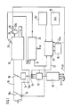
- FIG. 1 shows schematically a possible exemplary embodiment of a circuit for self-diagnosis of actuators using discrete components of a block diagram
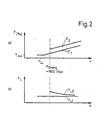
- FIG. 2 shows curves of the actuator opening as a percentage of an idle charge control and related load signals, in each case above the speed when an internal combustion engine is in overrun.
- the basic idea of the present invention is to control the actuator of a specific control system in the case of combined regulating or control systems, specifically in those operating states in which the controlled system controlled by this regulating system shows no or almost no reactions to the actuator change, that is to say no corresponding changes ( undesirable) effects and insofar as there is no influence on the actual value of this control system, but in doing so evaluate the sinal of another actual value that belongs to another control system but is correlated with the size controlled by the relevant actuator.
- the description given below of the preferred exemplary embodiment of the invention is therefore to be evaluated with regard to the overall functional and time sequence, the mode of operation achieved by the blocks discussed in each case and with regard to the respective interaction of the subfunction (s) represented by the individual components, the references to the individual circuit blocks facilitate understanding of the present invention.
- the invention relates to the application example of a self-diagnosis of the idle charge control actuator (LFR actuator) when operating an internal combustion engine, which is therefore only discussed in detail below.
- LFR actuator idle charge control actuator
- the basic principle of such an idle charge control is that the controller 10 of the idle charge control has certain input signals relating to a speed setpoint, the speed actual value, the temperature of the internal combustion engine and the like. are supplied and this, without going into too much detail, supplies its downstream output stage 12 with a signal so that it can control the actual actuator, which is designed, for example, as a so-called two-winding rotary actuator, such that one belonging to the two-winding rotary actuator 13 Valve 13a, for example in an air bypass line 14 to intake pipe 15 with throttle valve 16 essentially closed (idling), controls the amount of air to be supplied to internal combustion engine 17 in such a way that the actual speed n, st , can be disregarded within predetermined limits. It is understood that such an embodiment of an idle charge regulator is only one of the possible embodiments.
- the combined system of controlled control and regulation of an internal combustion engine 17 further includes, in addition to the integrated idle charge control, an electrical or electronic injection control and / or ignition control, and possibly further control systems, including load detection via a pressure measurement or an air quantity or air mass measurement in the intake manifold 15.
- Such an air flow sensor is indicated in FIG. 1 by 18 and can schematically comprise a mechanically pivotable baffle flap 18a, the pivoting angle of which is a measure of that via the intake pipe of the internal combustion engine amount of air supplied is Q.
- the injection controller 20 uses, inter alia, this load signal Q and a speed list signal n ist and generates injection commands at its output which are fed to fuel injection valves 21.
- the injection controller 20 can also process a large number of other input signals and operating state signals which are fed to it and which are indicated overall by the arrow A in FIG. 1.
- the invention comes into play, in which the operating states of the internal combustion engine are first selected, in which the driver naturally does not actuate the accelerator pedal in normal operation of the motor vehicle, i.e. with the internal combustion engine running and without the function or the system being switched off, and in which an operation is also carried out changed control of the LFR actuator to change the amount of additional air it produces does not result in any unpleasant or unexpected effects on driving or engine behavior.
- a change in the actuator opening is carried out based on the normal LFR actuator value, namely by means of a correspondingly different control signal, and the change in the air quantity or mass or the measured intake manifold pressure, which is determined by this change, is checked.
- the changed actuator control can be carried out by influencing the LFR controller or its output stage 12 accordingly, or that the LFR actuator is supplied with a separate control signal via a connecting line 22 from a discrete diagnostic circuit 23. It should be emphasized again that this diagnostic circuit can also be part of the program flow of the microcomputer, for example the IlC-controlled Motronic / L-Jetronic systems.
- the operating states which are suitable for the diagnostic control of the LFR actuator are preferably sliding operating states of the internal combustion engine with overrun cutoff above a predetermined speed threshold (for example n> 1800 min- 1 ). If the actuator is opened further above this speed threshold, it can be checked at the same time whether this changes the load signal measured by the encoder 18, by setting up a possible drop in speed. Such an actuator control is otherwise not noticeable in driving behavior, since the fuel cut-off means that the injection is interrupted anyway and therefore only the air throughput through the intake manifold 15 and the internal combustion engine 17 changes.
- a predetermined speed threshold for example n> 1800 min- 1
- a load signal results for a normal, predetermined actuator opening T , depending on the rotational speed in the push mode, corresponding to the curve a in FIG. 2
- this load signal must have the value tL2 in Fig. 2 in accordance with the curve of the load signal versus the speed at b) in FIG. 2 enlarge.
- These data resulting from the diagram profiles in FIG. 2 can be part of an additional memory 24 for the diagnostic circuit 23, or are stored at a suitable location in the memory means of the microcomputers or microprocessors forming the control systems, so that it is possible for a GUT- Evaluation required correlation between diagnostic control of the actuator and the assigned load signal from the stored data.
- the special exemplary embodiment in FIG. 1 also has a fuel cut-off detection block 25 or a post-start detection block 25 ', which will be discussed in a moment.
- the diagnostic circuit 23 is preferably also supplied with an actual value signal of the rotational speed, which is also present during the operation of an internal combustion engine and is supplied, for example, by an encoder 26 in a suitable manner , for example inductively or capacitively, scans certain markings 27a on a crankshaft-synchronously rotating disk 27.
- an LFR actuator check to use the post-start according to block 25 'in FIG. 1 as a suitable operating state .
- an increased idle speed is initially set when the actuator opening is initiated by the LFR controller itself. Then the associated large amount of air is reduced by closing the actuator until the desired idle speed is reached.
- the variation of the air volume from the transmitter 18 as a result and correlated with the change in the actuator opening can also be checked for plausibility in the diagnostic circuit 23.
- the diagnosis process is also initiated by a suitable post-start signal; However, it is not the diagnostic circuit 23 which then controls the LFR actuator, but rather the control signal for the LFR actuator is fed to the latter and, in parallel, the diagnostic circuit 23 or corresponding areas in the microcomputer which, when the restart signal is present, simultaneously receives the load signal from another control loop is used as the actual value and compares the values and / or function curves supplied and / or measured to it with the stored assignments.
Description
Die Erfindung geht aus von einem Verfahren und einer Vorrichtung nach der Gattung des Hauptanspruchs bzw. des ersten Vorrichtungsanspruchs. Auf vielen Gebieten der Technik ist es üblich, bestimmte Größen, Werte oder Positionen durch Regelung oder Steuerung zu bestimmen, inden einem beliebigen Stellglied eine üblicherweise elektrische, einen bestimmten Funktionsverlauf aufweisende Größe von einem Regler zugeführt wird, der bestimmte Eingangssignale aus der ihm zugeordneten Regelstrecke verarbeitet und dash durch seine Stellgliedverstellung erzielte Ergebnis in sein Ansteuerverhalten, nämlich durch Auswertung von ihm gemessenem, entsprechendem Istwertgrößen einbezieht.The invention is based on a method and a device according to the type of the main claim and the first device claim. In many fields of technology, it is common to determine certain variables, values or positions by means of regulation or control, in which a variable, which is usually electrical and has a specific function profile, is fed to any actuator by a controller which processes certain input signals from the controlled system assigned to it and dash incorporates the result achieved by its actuator adjustment into its actuation behavior, namely by evaluating corresponding actual value variables measured by it.
Aus der US-A-4 414 950 in bekannt, die Funktionsfähigkeit eines Sensors mittels Plausibilitätsprüfung des Ausganssignals dieses Sensors anhand eines anderen Sensorsignals vorzunehmen, wobei sich diese andere Sensorsignal auf einen anderen Betriebsparameter bezieht und für eine andere Steuer- oder Regelaufgabe verarbeitet wird. So wird in der US-A-4 414 950 vorgeschlagen, die Funktionsfähigkeit eines Drehzahlsensors dadurch zu überprüfen, daß für einen vorgegebenen Betriebspunkt das Drehzahlsignal mit dem Ausgangssignal eines Druckmessers im Ansaugrohr des Brennkraftmaschine verglichen wird und die Funktionsfähigkeit des Drehzahlsensors dann festgestellt wird, wenn zwischen Drehzahlwert und Ansaugdruckwert eine vorgegebene Beziehung erfüllt ist.From US-A-4 414 950 it is known to carry out the functionality of a sensor by means of a plausibility check of the output signal of this sensor on the basis of another sensor signal, this other sensor signal relating to another operating parameter and being processed for another control or regulating task. It is proposed in US-A-4 414 950 to check the functionality of a speed sensor by comparing the speed signal for a given operating point with the output signal of a pressure gauge in the intake manifold of the internal combustion engine and determining the functionality of the speed sensor when between Speed value and intake pressure value a predetermined relationship is met.
Problematisch ist allerdings eine Diagnose des Stellglieds selbst, die durchgeführt werden könnte, ohne daß es in der diesem Stellglied zugeordneten oder von ihm kontrollierten Regelstrecke zu Reaktionen kommt, die nicht gewünscht sind und ohne daß es erforderlich ist, das System stillzulegen bzw. die Stellgliedbewegung durch die Zuordnung dann zusätzlich notwendig werdender Hardware-Komponenten zu erfassen und im Sinne einer Diagnose auszuwerten.A problem is, however, a diagnosis of the actuator itself, which could be carried out without reactions occurring in the control path assigned to or controlled by this actuator, which are not desired and without it being necessary to shut down the system or to move the actuator the assignment of additional hardware components that are then required to be recorded and evaluated in the sense of a diagnosis.
Als bekannt, jedenfalls als verfügbar kann dabei die Maßnahme angesehen werden, eine Stellgleiddiagnose einfach bei stillgelegtem System dadurch durchzuführen, daß man das jeweilige Stellglied, etwa durch Zuführung eines extern erzeugten Signals, betätigt und dann die Stellgliedreaktion einfach visuell oder, wo dies nicht möglich ist, beispielsweise durch Fühlen oder mittels eines Hörtestes feststellt.As known, in any case as available, the measure can be regarded as simply performing an actuator diagnosis with the system shut down by actuating the respective actuator, for example by supplying an externally generated signal, and then simply the actuator reaction visually or where this is not possible , for example by feeling or by means of a hearing test.
Aus der JP-A-57-186038 ist in diesem Zusammenhang bekannt, bei betätigtem Leerlaufschalter durch Überprüfen des momentanen Drezahlsignalwertes mittels einer Logikeinrichtung einen Fehlerzustand des Stellgliedes des Leerlaufsystems zu erkennen.In this context, it is known from JP-A-57-186038 to recognize an error state of the actuator of the idle system when the idle switch is actuated by checking the current speed signal value by means of a logic device.
Die folgenden Ausführungen beziehen sich speziell auf die Gegebenheiten bei der Stellglieddiagnose eines sogenannten Leerlauffüllungsreglers bei Brennkraftsmaschinen, für welche die vorliegende Erfindung in ihrer Anwendung besonders geeignet ist. Es versteht sich aber, daß die Erfindung nicht auf die durch sie möglich gewordene Eigendiagnose des LFR-Stellers bei einer Brennkraftmaschine beschränkt ist, sondern der erfindungsgemäße Rahmen Stellglieddiagnosen bei beliebigen Steuerungs- und Regelungssystemen ermöglicht.The following statements relate specifically to the conditions in the final control diagnosis of a so-called idle charge controller in internal combustion engines, for which the present invention is particularly suitable in its application. It goes without saying, however, that the invention is not limited to the self-diagnosis of the LFR actuator in an internal combustion engine that it has made possible, but rather that the framework according to the invention enables actuator diagnostics in any control and regulation systems.
Bleibt man bei dem bevorzugten Anwendungsgebiet im Bereich der Regelung von Brennkraftsmaschinen bzw. der den Betrieb eines Kraftfahrzeugs noch stärker überdeckender Regelungssysteme wie beispielsweise die unter der Bezeichnung Motronic oder L-Jetronic bekannten Systeme, die zum überwiegenden Teil von Mikrorechnern gesteuert sind (pC-gesteuert), dann sind bei solchen Einrichtungen Eigendiagnosen der beteiligten Komponenten in zunehmendem Maße gewünscht und erforderlich. Die Überprüfung der Geber des jeweiligen Systems ist vergleichsweise einfach möglich, da die Gebersignale als Eingangsgrößen im Rechner vorliegen und durch eine entsprechende Subroutine leicht auf Plausibilität überprüft werden können. Die Überprüfung der von den Reglern oder Steuerungen angesteuerten Stellglieder ist jedoch wesentlich aufwendiger, da von den jeweiligen Ausgängen mindestens Rückführungen zum Rechner nötig wären, die eine zusätzliche Hardware-Komponente bedeuten (Verdrahtung), außerdem aber eine mechanische Beschädigung des Stellglieds selbst (beispielsweise ein Verklemmen des LFR-Stellers) gar nicht erkennen lassen.If you stay with the preferred field of application in the field of control of internal combustion engines or control systems that cover the operation of a motor vehicle even more, such as the systems known under the name Motronic or L-Jetronic, which are mainly controlled by microcomputers (PC-controlled) , then self-diagnosis of the components involved is increasingly desired and required in such facilities. It is comparatively easy to check the sensors of the respective system, since the sensor signals are available as input variables in the computer and can be easily checked for plausibility by means of a corresponding subroutine. Checking the actuators controlled by the controllers or controls is, however, much more complex, since at least returns to the computer would be required from the respective outputs, which would mean an additional hardware component (wiring), but also mechanical damage to the actuator itself (e.g. jamming) of the LFR controller) cannot be recognized at all.
Es besteht daher Bedarf nach der Möglichkeit, bei Stellgliedern von Steuerungen oder Regelungen eine Eigendiagnose ohne zusätzlichen Hardware-Aufwand durchzuführen, wobei einmal der Normalbetrieb des gesteuerten oder geregelten Systems nicht gestört wird, andererseits aber eine echte, mindestens mittelbar auf die Stellgliedbeweguhg zurückzuführende Rückmeldung zur Auswertung gelangen kann.There is therefore a need for the possibility to carry out self-diagnosis for actuators of control systems without additional hardware expenditure, whereby the normal operation of the controlled or regulated system is not disturbed, but on the other hand there is real feedback, at least indirectly attributable to the actuator movement, for evaluation can reach.
n;L7as erfindungsgemäße Verfahren mit den anzeichnenden Merkmalen des Hauptanspruchs bzw. die erfindungsgemäße Vorrichtung mit den kennzeichnenden Merkmalen des ersten Vorrichtungsanspruchs haben den Vorteil, daß ohne jeden zusätzlichen Aufwand eine Eigendiagnose von Stellgliedern einschließlich deren mechanischer Funktion möglich ist, wobei keinerlei zusätzliche Hardware-Komponenten benötigt werden und die Diagnose auch, je nach Ausbildung und Integration der beteiligten Systeme, mindestens teilweise durch einen Programmablauf und dem Vergleich gemessener zu gespeicherten Werten in bestimmten Zeitintervallen durchgeführt werden kann, gegebenenfalls von den gleichen Mikroprozessoren oder Kleinrechnern, die für die eigentliche Stellgliedansteuerung im Regelsystem verantwortlich sind. n; L7as the method according to the invention with the characterizing features of the main claim or the device according to the invention with the characterizing features of the first device claim have the advantage that self-diagnosis of actuators including their mechanical function is possible without any additional effort, no additional hardware components being required and Depending on the training and integration of the systems involved, the diagnosis can also be carried out at least in part by running a program and comparing measured and stored values at specific time intervals, if necessary by the same microprocessors or small computers that are responsible for the actual control of the control element in the control system.
Die Erfindung ist dabei so ausgelegt, daß sie die Folge einer zur Eigendiagnose vorgenommenen Ansteuerung des Stellgliedes mindestens indirekt erfaßt, und zwar anhand einer Istwertgröße, die für andere Regelzwecke ohnehin durch geeignete Istwertgeber aufbereitet und dem Gesamtsystem zugeführt wird. Angewendet auf das spezielle Ausführungsbeispiel einer Eigendiagnose des Stellglieders einer Leerlauffüllungsregelung beim Betrieb einer Brennkraftmaschine bedeutet dies, daß als Istwert eine Druckmessung bzw. Luftmengen- oder Luftmassenmessung im Saugrohr der Brennkraftmaschine, auch als Funktion, ausgewertet wird für die zu überprüfende Reaktion des LFR-Stellers, wobei die Regelung, zu welcher der LFR-Steller eine Teilkomponente bildet, auf Luftwerte bezogene Angaben gar nicht benötigt, sondern selbst als Istwert eine Drehzahlgröße benutzt.The invention is designed so that it is the result of a self-diagnosis Control of the actuator is detected at least indirectly, using an actual value, which is prepared for other control purposes anyway by suitable actual value transmitters and supplied to the overall system. Applied to the special exemplary embodiment of a self-diagnosis of the actuator of an idle charge control when operating an internal combustion engine, this means that a pressure measurement or air volume or air mass measurement in the intake manifold of the internal combustion engine, also as a function, is evaluated as the actual value for the reaction of the LFR actuator to be checked, the control, for which the LFR actuator forms a sub-component, does not need any information relating to air values, but uses a speed variable as the actual value.
Dabei ist die Erfindung in der Lage, nicht nut einen bestimmten Arbeitspunkt des Stellgliedes auf einwandfreie Funktion zu überprüfen, sondern die gesamte Stellervariation abzufahren, über diesen Funktionsverlauf auch mechanische Beschädigungen, etwa ein Verklemmen des Stellers zu erkennen und gleichzeitig Wackelkontakte oder sonstige Störungen im Stellerkreis zu erfassen.The invention is able to check not only a certain working point of the actuator for proper function, but to run the entire actuator variation, to detect mechanical damage, such as jamming of the actuator, and at the same time to loose contacts or other faults in the actuator circuit to capture.
Durch die in den Unteransprüchen aufgeführten Maßnahmen sind vorteilhafte Weiterbildungen und Verbesserungen der Erfindung möglich.Advantageous further developments and improvements of the invention are possible through the measures listed in the subclaims.
Ein Ausführungsbeispiel der Erfindung ist in der Zeichnung dargestellt und wird in der nachfolgenden Beschreibung näher erläutert. Es zeigen Fig. 1 schematisiert ein mögliches Ausführungsbeispiel einer Schaltung zur Eigendiagnose von Stellgliedern anhand von diskreten Komponenten eines Blockschaltbildes und Fig. 2 Kurvenverläufe der Stelleröffnung in Prozent einer Leerlauffüllungsregelung und auf diese bezogen entsprechende Lastsignale, jeweils über der Drezahl im Schiebebetrieb einer Brennkraftmaschine.An embodiment of the invention is shown in the drawing and is explained in more detail in the following description. 1 shows schematically a possible exemplary embodiment of a circuit for self-diagnosis of actuators using discrete components of a block diagram, and FIG. 2 shows curves of the actuator opening as a percentage of an idle charge control and related load signals, in each case above the speed when an internal combustion engine is in overrun.
Der Grundgedanke vorliegender Erfindung besteht darin, bei kombinierten Regel- oder Steuerungssystemen das Stellglied eines bestimmten Regelsystems anzusteuern, und zwar bei solchen Betriebszuständen, bei denen die von diesem Regelsystem beherrschte Regelstrecke keiner oder nahezu keine Reaktionen auf die Stellgliedänderung zeigt, sich also keine entsprechenden, (unerwünschten) Auswirkungen ergeben und insofern auch kein Einfluß auf die Istwertgröße dieses Regelsystems erfolgen kann, dabei aber das Sinal einer anderen Istwertgröße auszuwerten, die zu einem anderen Regelsystem gehört, jedoch mit der von dem betreffenden Stellglied geregelten Größe korreliert ist.The basic idea of the present invention is to control the actuator of a specific control system in the case of combined regulating or control systems, specifically in those operating states in which the controlled system controlled by this regulating system shows no or almost no reactions to the actuator change, that is to say no corresponding changes ( undesirable) effects and insofar as there is no influence on the actual value of this control system, but in doing so evaluate the sinal of another actual value that belongs to another control system but is correlated with the size controlled by the relevant actuator.
In diesem Zusammenhang sei zunächst darauf hingewiesen, daß die folgenden Erläuterungen der Erfindung diese anhand eines möglichen Ausführungsbeispiels eines Blockschaltbildes angeben, die Erfindung jedoch auf die diskrete Schaltstufendarstellung nicht beschränkt ist, die daher ausschließlich die funktionellen Grundwirkungen der Erfindung veranschaulichen und spezielle Funktionsabläufe in jedenfalls einer möglichen Realisierungsform angeben soll. Es versteht sich, daß die einzelnen Bausteine und Blöcke an analoger, digitaler oder auch hybrider Technik aufgebaut sein können, oder auch, ganz oder teilweise zusammengefaßt, entsprechende Bereich von programmgesteuerten digitalen Systemen, beispielsweise also Mikroprozessoren, Mikrorechner, digitale oder analoge Logikschaltungen o.dgl. umfassen können. Die im folgenden angegebene Beschreibung des bevorzugten Ausführungsbeispiels der Erfindung ist daher bezüglich des funktionellen Gesamt- und Zeitablaufs, der durch die jeweils besprochenen Blöcke erzielten Wirkungsweise und bezüglich des jeweiligen Zusammenwirkens der durch die einzelnen Komponenten dargestellten Teilfunktion(en) zu werten, wobei die Hinweise auf die einzelnen Schaltungsblöcke das Verständis der vorliegenden Erfindung erleichtern. Speziell bezieht sich der Erfindung auf das Anwendungsbeispiel einer Eigendiagnose des Leerlauffüllungsregelungs-Stellers (LFR-Stellers) beim Betrieb einer Brennkraftmaschine, auf die daher im folgenden lediglich noch im einzelnen eingegangen wird.In this context, it should first be pointed out that the following explanations of the invention indicate this using a possible exemplary embodiment of a block diagram, but the invention is not restricted to the discrete switching stage representation, which therefore only illustrate the basic functional effects of the invention and special functional sequences in any case possible Realization form should specify. It goes without saying that the individual modules and blocks can be constructed using analog, digital or else hybrid technology, or else, in whole or in part, corresponding areas of program-controlled digital systems, for example microprocessors, microcomputers, digital or analog logic circuits or the like . can include. The description given below of the preferred exemplary embodiment of the invention is therefore to be evaluated with regard to the overall functional and time sequence, the mode of operation achieved by the blocks discussed in each case and with regard to the respective interaction of the subfunction (s) represented by the individual components, the references to the individual circuit blocks facilitate understanding of the present invention. In particular, the invention relates to the application example of a self-diagnosis of the idle charge control actuator (LFR actuator) when operating an internal combustion engine, which is therefore only discussed in detail below.
Das Grundprinzip einer solchen Leerlauffülungsregelung besteht darin, daß dem Regler 10 der Leerlauffüllungsregelung bestimmte Eingangssignale bezüglich eines Drehzahlsollwertes, des Drehzahlistwertes, der Temperatur der Brennkraftsmachine u.dgl. zugeführt werden und dieser, ohne zu stark auf Einzelheiten einzugehen, seiner nachgeschalteten Endstufe 12 ein Signal zuführt, so daß diese das eigentliche Stellglied, welches beispielsweise als sogenannter Zweiwicklungs-Drehsteller ausgebildet ist, so ansteuern kann, daß ein zu dem Zweiwicklungs-Drehsteller 13 gehörendes Ventil 13a beispielsweise in einer Luftbypaßleitung 14 zum Ansaugrohr 15 bei im wesentlichen geschlossener Drosselklappe 16 (Leerlauf) die der Brennkraftmaschine 17 zuzuführende Luftmenge so steuert, daß die, Istdrehzahl n,st,'nnerhaib vorgegebener Grenzentgehatten werdenckann. Es versteht sich, daß einer solches Ausführungsbeispiel eines Leerlaüffüllungsreglers nur eine der möglichen Ausführungsformen darstellt.The basic principle of such an idle charge control is that the
Das kombinierte System der gesteuerten Führung und Regelung einer Brennkraftsmaschine 17 umfaßt ferner, neben der insbesondere auch integrierten Leerlauffüllungsregelung, eine elektrische oder elektronische Einspritzregelung und/ oder Zündungsregelung, gegebenenfalls noch weitere Regelungssysteme, einschließlich einer Lasterfassung über eine Druckmessung oder eine Luftmengen- oder Luftmassenmessung im Saugrohr 15. Ein solcher Luftmengengeber, wie er im folgenden lediglich nocht gennant werden soll, ist in Fig. 1 mit 18 angegeben und kann schematisch eine mechanisch verschwenkbare Stauklappe 18a umfassen, deren Verschwenkwinkel ein Maß für die über das Saugrohr der Brennkraftmaschine zugeführte Luftmenge Q ist. Der Einspritzregler 20 benutzt u.a. dieses Lastsignal Q und eine Drehzahlistsignal nist und erzeugt an seinem Ausgang Einspritzbefehle, die Kraftstoffeinspritzventilen 21 zugeführt werden. Hierzu kann die Einspritzregelung 20 noch eine Vielzahl anderer, ihr zugeführter Eingangssignale und Betriebszustandssignale verarbeiten, die in Fig. 1 insgesamt durch den Pfeil A gekennzeichnet sind.The combined system of controlled control and regulation of an
Genauer braucht zum Verständis vorliegender Erfindung auf die einzelnen Unterregelsysteme eines kombinierten Gesamtsystems nicht eingegangen zu werden - man erkennt aber, daß eine Überprüfung des LFR-Stellers 13 bis zu seiner mechanischen Funktionsfähigkeit mindestens sehr aufwenig und umständlich ist, da jedenfalls über die vom Ventil 13 jeweils eingenommene Stellung Angaben nicht vorliegen und schon die Rückführung lediglich der elektrischen Ansteuersignale für den LFR-Steller zusätzliche Verdrahtungsmittel (Hardware) erforderlich machen würden.To understand the present invention, it is not necessary to go into detail about the individual sub-control systems of a combined overall system - but it can be seen that a check of the
Hier setzt die Erfindung ein, wobei zunächst Betriebszustände der Brennkraftmaschine ausgesucht werden, in denen der Fahrer im Normalbetrieb des Kraftfahrzeugs selbstverständlich, also bei laufender Brennkraftmaschine und ohne daß die Funktion oder das Systems abegeschaltet sind, keine Betätigung des Gaspedals durchführt, und in denen ferner eine veränderte Ansteuerung des LFR-Stellers zur Veränderung der von ihm erbrachten Zusatzluftmenge keine unangenehmen oder unerwarteten Auswirkungen auf das Fahr- bzw. Motorverhalten zur Folge hat. In solchen Betriebszuständen wird dann von dem normalen LFR-Stellerwert ausgehend eine Änderung der Stelleröffnung, nämlich durch ein entsprechend unterschiedliches Ansteuersignals, durchgeführt und die durch diese Änderung bewirkte, durch Messung festgestellte Änderung der Luftmenge bzw. -masse oder des gemessenen Saugrohrdrucks überprüft. Es versteht sich, daß die geänderte Stelleransteurung durch entsprechende Beeinflussung des LFR-Reglers oder seiner Endstufe 12 vorgenommen werden kann, oder daß dem LFR-Steller ein separates Ansteuersignal über eine Verbindungsleitung 22 von einer diskreten Diagnoseschaltung 23 zugeführt wird. Es sei nochmals betont, daß diese Diagnoseschaltung aber auch Teil des Programmablaufs des Mikrorechners, also beispielsweise der IlCgesteuerten Motronic/L-Jetronic-Systeme sein kann.This is where the invention comes into play, in which the operating states of the internal combustion engine are first selected, in which the driver naturally does not actuate the accelerator pedal in normal operation of the motor vehicle, i.e. with the internal combustion engine running and without the function or the system being switched off, and in which an operation is also carried out changed control of the LFR actuator to change the amount of additional air it produces does not result in any unpleasant or unexpected effects on driving or engine behavior. In such operating states, a change in the actuator opening is carried out based on the normal LFR actuator value, namely by means of a correspondingly different control signal, and the change in the air quantity or mass or the measured intake manifold pressure, which is determined by this change, is checked. It goes without saying that the changed actuator control can be carried out by influencing the LFR controller or its
Als Betriebszustände, die sich für die Diagnoseansteuerung des LFR-Stellers eignen, sind bevorzugt Schiebebetriebszuständende der Brennkraftmaschine mit Schubabschaltung oberhalb einer vorgegebenen Drehzahlschwelle (beispielsweise n > 1800 min-1) geeignet. Wird oberhalb diese Drehzahlschwelle der Steller weiter geöffnet, dann kann gleichzeitig überprüft werden, ob sich hierdurch das vom Geber 18 gemessene Lastsignal ändert, unter Einrichtung eines eventuell stattfindenden Drezahlabfalls. Eine solche Stelleransteuerung macht sich im übrigen im Fahrverhhalten in keiner Weise bemerkbar, da durch die Schubabschaltung die Einspritzung ohnehin unterbrochen ist und sich daher lediglich der Luftdurchsatz durch das Saugrohr 15 und die Brennkraftmaschine 17 ändert.The operating states which are suitable for the diagnostic control of the LFR actuator are preferably sliding operating states of the internal combustion engine with overrun cutoff above a predetermined speed threshold (for example n> 1800 min- 1 ). If the actuator is opened further above this speed threshold, it can be checked at the same time whether this changes the load signal measured by the
Bezieht man sich auf das Beispiel eines luftmengenmessenden Systems, dann ergibt sich für eine normale, vorgegebene Stelleröffnung T, in Abhängigkeit zur Drehzahl im Schiebebetrieb entsprechend dem Kurvenverlauf a in Fig. 2 ein Lastsignal
Wird nun entsprechend dem Diagnose-Ansteuersignal der Steller kurzzeitig z.B. auf das Tastverhältnis (im Ansteuersignal für den Zweiwicklungs-Drehsteller) T2 geöffnet, dann muß sich entsprechend dem Kurvenverlauf des Lastsignals über der Drehzahl bei b) in Fig. 2 dieses Lastsignal auf den Wert tL2 vergrößern. Diese sich aus den Diagrammverläufen der Fig. 2 ergebenden Daten können Teil eines zusätzlichen Speichers 24 zur Diagnoseschaltung 23 sein, oder sind an geeigneter Stelle in den Speichermitteln der die Regelsysteme bildenden Mikrorechner oder Mikroprozessoren abgelegt, so daß es möglich ist, die für eine GUT-Bewertung erforderliche Korrelation zwischen Diagnoseansteurung des Stellers und dem zugeordneten Lastsignal aus den gespeicherten Daten zu entnehmen.If, according to the diagnostic control signal, the actuator is briefly opened, e.g. to the duty cycle (in the control signal for the two-winding rotary actuator) T2 , then this load signal must have the value tL2 in Fig. 2 in accordance with the curve of the load signal versus the speed at b) in FIG. 2 enlarge. These data resulting from the diagram profiles in FIG. 2 can be part of an
Da nur bei bestimmten Betriebszuständen die Eigendiagnose erfolgen soll, verfügt das spezielle Ausführungsbeispiel der Fig. 1 noch über einen Schubabschaltungs-Erkennungsblock 25 bzw. einen Nachstart-Erkennungsblock 25', auf den gleich noch eingegangen wird. Der Diagnoseschaltung 23 wird also neben der Angabe der von ihr für die Durchführung geeigneten Diagnose des Stellers erforderlichen Betriebszustände vorzugsweise noch ein Istwertsignal der Drehzahl zugeführt, welches ja ebenfalls beim Betrieb einer Brennkraftmaschine vorhanden ist und beispielsweise von einem Geber 26 geliefert wird, der in geeigneter Weise, beispielsweise induktiv oder kapazitiv, bestimmte Markierungen 27a an einer kurbelwellensynchron drehenden Scheibe 27 abtastet.Since the self-diagnosis should only take place in certain operating states, the special exemplary embodiment in FIG. 1 also has a fuel cut-
Je nach Ausmaß der sich ergebenden Scheibebetriebsdrehzahlen und der Dauer des Schiebebetriebs ist es natürlich möglich, die gesamte Stellervariation abzufahren und daher auch den funktionellen Verlauf und das einwandfreie Arbeiten des Stellers bei Ändergung der ihm zugeführten Eingangssignale zu überprüfen. Wird eine ganzer Funktionsverlauf in der Stellerposition abgefahren, dann ist es auch möglich, Wackelkontakte, u.dgl. festzustellen, wenn nämlich beispielsweise einer kontinuierlichen Änderung des Stelleransteuersignals oder Diagnosesignals sprunghafte Lastsignaländerungen folgen. Durch die ständig durchgeführte Korrelation des bei einem bestimmten Diagnoseansteuersignals für den Steller zu erwartenden Lastsignals ist eine schnelle und, falls gewünscht, sich bei bestimmten Betriebszuständen stets wiederholende Eigendiagnose des Stellglieds möglich.Depending on the extent of the resulting disk operating speeds and the duration of the pushing operation, it is of course possible to run through the entire actuator variation and therefore also to check the functional course and the flawless operation of the actuator when the input signals supplied to it change. If an entire function sequence is followed in the actuator position, then it is also possible to have loose contacts, etc. to determine if, for example, a continuous change in the actuator control signal or diagnostic signal is followed by sudden load signal changes. Due to the constant correlation of the at a certain diagnostic control signal for the load signal to be expected from the actuator is quick and, if desired, self-diagnosis of the actuator which is always repetitive in certain operating states possible.
Es versteht sich, daß eine solche Eigendiagnose nicht auf den einen Brennkraftsmaschinenbetriebszustand der Schubabschaltung beschränkt zu bleiben braucht - es ist als weiteres Ausführungsbeispiel für eine LFR-Steller- überprüfung auch möglich, als geeigneten Betriebszustand etwa den Nachstart entsprechend Block 25' in Fig. 1 heranzuziehen. Bei einem Nachstart wird zunächst bei großer, vom LFR-Regler selbst veranlaßter Stelleröffnung eine erhöhte Leerlaufdrehzahl eingestellt. Anschließend wird durch Schließen des Stellers die dazugehörige große Luftmenge abgeregelt, bis sich die jeweils angestrebte Leerlauf-Solldrehzahl einstellt. Unter entsprechender Berücksichtigung der Istdrehzahländerung kann daher ebenfalls die Variation der Luftmenge vom Geber 18 als Folge und korreliert zur Steller-Öffnungsänderung auf Plausibilität in der Diagnoseschaltung 23 überprüft werden.It goes without saying that such self-diagnosis need not be limited to the one internal combustion engine operating state of the overrun fuel cutoff - it is also possible as a further exemplary embodiment for an LFR actuator check to use the post-start according to block 25 'in FIG. 1 as a suitable operating state . During a post-start, an increased idle speed is initially set when the actuator opening is initiated by the LFR controller itself. Then the associated large amount of air is reduced by closing the actuator until the desired idle speed is reached. With appropriate consideration of the actual speed change, the variation of the air volume from the
Im letzteren Fall erfolgt die Einleitung des Diagnosevorgangs zwar ebenfalls durch ein geeignetes Nachstart-Signal; es ist aber nicht die Diagnoseschaltung 23, die dann den LFR-Steller ansteuert, sondern das Ansteuersignal für den LFR-Steller wird diesem und parallel der Diagnoseschaltung 23 oder entsprechenden Bereichen im Mikrorechner zugeführt, der bei Vorliegen des Nachstartsignals gleichzeitig das Lastsignal aus einem anderen Regelkreis als Istwert heranzieht und die ihm zugeführten und/ oder gemessenen Werte oder Funktionsverläufe mit den gespeicherten Zuordnungen vergleicht.In the latter case, the diagnosis process is also initiated by a suitable post-start signal; However, it is not the
Claims (8)
Applications Claiming Priority (4)
| Application Number | Priority Date | Filing Date | Title |
|---|---|---|---|
| DE3428620 | 1984-08-03 | ||
| DE3428620 | 1984-08-03 | ||
| DE3435465 | 1984-09-27 | ||
| DE19843435465 DE3435465A1 (en) | 1984-08-03 | 1984-09-27 | METHOD AND DEVICE FOR THE SELF-DIAGNOSIS OF ACTUATORS |
Publications (3)
| Publication Number | Publication Date |
|---|---|
| EP0170018A2 EP0170018A2 (en) | 1986-02-05 |
| EP0170018A3 EP0170018A3 (en) | 1988-03-23 |
| EP0170018B1 true EP0170018B1 (en) | 1990-10-03 |
Family
ID=25823538
Family Applications (1)
| Application Number | Title | Priority Date | Filing Date |
|---|---|---|---|
| EP19850107387 Expired - Lifetime EP0170018B1 (en) | 1984-08-03 | 1985-06-14 | Process and apparatus for the self-testing of control levers |
Country Status (5)
| Country | Link |
|---|---|
| US (1) | US4601199A (en) |
| EP (1) | EP0170018B1 (en) |
| JP (1) | JPH065197B2 (en) |
| BR (1) | BR8503654A (en) |
| DE (2) | DE3435465A1 (en) |
Cited By (2)
| Publication number | Priority date | Publication date | Assignee | Title |
|---|---|---|---|---|
| DE4229774C2 (en) * | 1992-09-05 | 2002-06-20 | Bosch Gmbh Robert | Device for controlling an internal combustion engine |
| DE19707868B4 (en) * | 1997-02-27 | 2008-10-30 | Robert Bosch Gmbh | Method and device for monitoring a system for controlling an internal combustion engine |
Families Citing this family (38)
| Publication number | Priority date | Publication date | Assignee | Title |
|---|---|---|---|---|
| JPS62649A (en) * | 1985-06-25 | 1987-01-06 | Honda Motor Co Ltd | Output timing abnormality detecting method for control device for internal-combustion engine |
| JPH0663471B2 (en) * | 1986-02-13 | 1994-08-22 | 本田技研工業株式会社 | Auxiliary air amount control device for internal combustion engine |
| US4943924A (en) * | 1986-06-27 | 1990-07-24 | Nissan Motor Company, Limited | Trouble checking apparatus |
| DE3624441A1 (en) * | 1986-07-19 | 1988-01-28 | Bosch Gmbh Robert | Diagnostic method for quantitative testing of actuators in internal-combustion engines |
| JPS6388248A (en) * | 1986-10-01 | 1988-04-19 | Toyota Motor Corp | Trouble diagnostic device for exhaust gas purifying device |
| DE3730513A1 (en) * | 1987-09-11 | 1989-03-23 | Triumph Adler Ag | Circuit arrangement for a device for controlling the idling charge in internal combustion engines |
| DE3802771A1 (en) * | 1988-01-30 | 1989-08-10 | Bosch Gmbh Robert | SAFETY SYSTEM FOR INTERNAL COMBUSTION ENGINES |
| DE3803078C2 (en) * | 1988-02-03 | 2000-11-02 | Bosch Gmbh Robert | Method and device for monitoring the position of an electrical actual position transmitter |
| DE3808381C2 (en) * | 1988-03-12 | 1996-07-11 | Bosch Gmbh Robert | Method and device for monitoring a safety stop in internal combustion engines |
| DE3808382A1 (en) * | 1988-03-12 | 1989-09-21 | Bosch Gmbh Robert | Method and device for monitoring a safety cut-off in internal combustion engines |
| JPH0623736Y2 (en) * | 1988-08-10 | 1994-06-22 | トヨタ自動車株式会社 | Evaporative Purge Abnormality Detection Device for Internal Combustion Engine |
| DE3828932A1 (en) * | 1988-08-26 | 1990-03-01 | Teves Gmbh Alfred | Method for monitoring the operation of a hydraulic, pneumatic, mechanical and/or electrical device |
| JPH02105034A (en) * | 1988-10-14 | 1990-04-17 | Mitsubishi Electric Corp | Fault diagnostic device |
| US4875456A (en) * | 1989-02-08 | 1989-10-24 | Japan Electronic Control Systems Company Limited | Self-diagnosis system for auxiliary air control system of internal combustion engine |
| DE3914536C2 (en) * | 1989-05-02 | 1998-05-14 | Bosch Gmbh Robert | Method and device for diagnosing actuators in the regulation and / or control of operating parameters in connection with the idle control and the tank ventilation in internal combustion engines |
| US4974444A (en) * | 1989-07-05 | 1990-12-04 | Ford Motor Company | Electronically controlled engine throttle plate adjustment |
| DE3925881A1 (en) * | 1989-08-04 | 1991-02-07 | Bosch Gmbh Robert | METHOD AND DEVICE FOR CONTROLLING AND / OR REGULATING THE ENGINE POWER OF AN INTERNAL COMBUSTION ENGINE OF A MOTOR VEHICLE |
| DE3942836A1 (en) * | 1989-12-23 | 1991-06-27 | Daimler Benz Ag | METHOD FOR DETECTING THE MOTION AND POSITION OF A COMPONENT OF A INDUCTIVE ELECTRICAL CONSUMER THROUGH MAGNETIC INTERACTION BETWEEN TWO END POSITIONS |
| DE4005973A1 (en) * | 1990-02-26 | 1991-09-05 | Bosch Gmbh Robert | DIAGNOSTIC METHOD FOR CHECKING ACTUATORS FOR CONTROLLING INTERNAL COMBUSTION ENGINES |
| JPH041451A (en) * | 1990-04-17 | 1992-01-06 | Mitsubishi Electric Corp | Trouble diagnoser for engine |
| DE4024036A1 (en) * | 1990-07-28 | 1992-01-30 | Audi Ag | Draught-sensitive controlled operation of IC engine - checking idling speed control with assessment of plausibility of throttle by=pass valve motor current |
| DE4130846A1 (en) * | 1991-09-17 | 1993-03-18 | Egm Entwicklung Montage | METHOD FOR TESTING COMPONENTS FOR COMBUSTION ENGINES |
| DE4220286C2 (en) * | 1992-06-20 | 2001-08-09 | Bosch Gmbh Robert | Method for checking the function of an actuator in a vehicle |
| JPH07119559A (en) * | 1993-10-26 | 1995-05-09 | Mitsubishi Electric Corp | Controller for internal combustion engine |
| JPH07311620A (en) * | 1994-05-17 | 1995-11-28 | Nec Corp | Fault detection device for control computer |
| DE4419548B4 (en) * | 1994-06-03 | 2004-02-19 | Samson Ag | Procedure for monitoring the functionality of a pneumatic actuator |
| DE59503378D1 (en) * | 1994-10-26 | 1998-10-01 | Siemens Ag | METHOD FOR ANALYZING A MEASURED VALUE AND MEASURED VALUE ANALYZER FOR IMPLEMENTING THE METHOD |
| DE19643297C1 (en) * | 1996-10-21 | 1998-03-12 | Samson Ag | In-service monitoring method for servo equipment |
| DE19650828B4 (en) * | 1996-12-07 | 2005-09-29 | Robert Bosch Gmbh | Tester for checking a control unit |
| DE19923296A1 (en) * | 1999-05-21 | 2000-12-07 | Baelz Gmbh Helmut | Central heating supply installation includes sensors and control system enabling shut-down in event of remote fault at point of delivery |
| DE10001583C2 (en) * | 2000-01-17 | 2002-03-21 | Bosch Gmbh Robert | Method and device for monitoring the function of a gas flow control element, in particular a swirl cap, in an internal combustion engine |
| DE10039952C2 (en) * | 2000-08-16 | 2003-04-24 | Siemens Ag | Procedure for checking an exhaust gas recirculation system |
| DE10053334B4 (en) | 2000-10-27 | 2018-08-02 | Robert Bosch Gmbh | Method and device for controlling an actuating element in a vehicle |
| DE10145906A1 (en) * | 2001-09-18 | 2003-04-10 | Bosch Gmbh Robert | Method for carrying out remote diagnosis in a motor vehicle, vehicle diagnosis module and service center |
| DE10320031A1 (en) * | 2003-05-06 | 2004-12-16 | Samson Ag | Safety actuator testing method for checking the operation of actuators and control elements in a safety circuit of a process control system, whereby the control elements are partially moved and their movement detected with sensors |
| DE102004039138B4 (en) * | 2004-08-12 | 2009-02-19 | Bosch Rexroth Pneumatics Gmbh | valve unit |
| DE102006010542B3 (en) | 2006-03-07 | 2007-08-23 | Siemens Ag | Fault variable-servo unit detecting method for internal combustion engine, involves comparing regulating signal with threshold value, so that defect of servo unit is recognized when regulating signal exceeds threshold value |
| JP5144169B2 (en) * | 2007-08-17 | 2013-02-13 | 本田技研工業株式会社 | Cogeneration equipment |
Citations (1)
| Publication number | Priority date | Publication date | Assignee | Title |
|---|---|---|---|---|
| JPS57186038A (en) * | 1981-05-11 | 1982-11-16 | Automob Antipollut & Saf Res Center | Idle speed controller |
Family Cites Families (10)
| Publication number | Priority date | Publication date | Assignee | Title |
|---|---|---|---|---|
| IT1081383B (en) * | 1977-04-27 | 1985-05-21 | Magneti Marelli Spa | ELECTRONIC EQUIPMENT FOR THE CONTROL OF THE POWER OF AN AIR / PETROL MIXTURE OF AN INTERNAL COMBUSTION ENGINE |
| DE2846804C2 (en) * | 1978-10-27 | 1982-08-12 | Volkswagenwerk Ag, 3180 Wolfsburg | Method and arrangement for achieving a correction of a characteristic which is stored in a control device for a fuel metering element of an internal combustion engine |
| JPS5596339A (en) * | 1979-01-13 | 1980-07-22 | Nippon Denso Co Ltd | Air-fuel ratio control method |
| JPS55126841A (en) * | 1979-03-23 | 1980-10-01 | Nissan Motor Co Ltd | Diagnosing method of controller for motorcar |
| DE2935585C2 (en) * | 1979-09-04 | 1982-04-08 | Dürkoppwerke GmbH, 4800 Bielefeld | Circuit arrangement for the continuity test that can be carried out with direct voltage |
| JPS5770931A (en) * | 1980-10-06 | 1982-05-01 | Honda Motor Co Ltd | Trouble backup device for air fuel ratio feddback controller of internal combustion engine |
| DE3128245A1 (en) * | 1981-07-17 | 1983-01-27 | Dr.Ing.H.C. F. Porsche Ag, 7000 Stuttgart | "METHOD FOR CONTROLLING THE COMBUSTION PROCESS IN INTERNAL COMBUSTION ENGINES" |
| DE3211644A1 (en) * | 1982-03-30 | 1983-10-13 | Daimler-Benz Ag, 7000 Stuttgart | DEVICE FOR DETECTING THE FAILURE OF A SENSOR |
| JPS595310A (en) * | 1982-07-02 | 1984-01-12 | Nissan Motor Co Ltd | Vehicle fault diagnosing device |
| JPS5925056A (en) * | 1982-08-03 | 1984-02-08 | Toyota Motor Corp | Control method of idling speed of internal combustion engine |
-
1984
- 1984-09-27 DE DE19843435465 patent/DE3435465A1/en not_active Withdrawn
-
1985
- 1985-06-14 DE DE8585107387T patent/DE3579972D1/en not_active Expired - Lifetime
- 1985-06-14 EP EP19850107387 patent/EP0170018B1/en not_active Expired - Lifetime
- 1985-07-11 US US06/754,514 patent/US4601199A/en not_active Expired - Lifetime
- 1985-07-24 JP JP60162193A patent/JPH065197B2/en not_active Expired - Lifetime
- 1985-08-02 BR BR8503654A patent/BR8503654A/en not_active IP Right Cessation
Patent Citations (1)
| Publication number | Priority date | Publication date | Assignee | Title |
|---|---|---|---|---|
| JPS57186038A (en) * | 1981-05-11 | 1982-11-16 | Automob Antipollut & Saf Res Center | Idle speed controller |
Cited By (2)
| Publication number | Priority date | Publication date | Assignee | Title |
|---|---|---|---|---|
| DE4229774C2 (en) * | 1992-09-05 | 2002-06-20 | Bosch Gmbh Robert | Device for controlling an internal combustion engine |
| DE19707868B4 (en) * | 1997-02-27 | 2008-10-30 | Robert Bosch Gmbh | Method and device for monitoring a system for controlling an internal combustion engine |
Also Published As
| Publication number | Publication date |
|---|---|
| JPS6145950A (en) | 1986-03-06 |
| DE3579972D1 (en) | 1990-11-08 |
| BR8503654A (en) | 1986-05-06 |
| JPH065197B2 (en) | 1994-01-19 |
| US4601199A (en) | 1986-07-22 |
| EP0170018A3 (en) | 1988-03-23 |
| DE3435465A1 (en) | 1986-02-13 |
| EP0170018A2 (en) | 1986-02-05 |
Similar Documents
| Publication | Publication Date | Title |
|---|---|---|
| EP0170018B1 (en) | Process and apparatus for the self-testing of control levers | |
| DE3624441C2 (en) | ||
| EP0470960B1 (en) | Process and device for checking the controllability of a tank ventilation valve | |
| DE102008001569B4 (en) | Method and device for adapting a dynamic model of an exhaust gas probe | |
| DE3914536C2 (en) | Method and device for diagnosing actuators in the regulation and / or control of operating parameters in connection with the idle control and the tank ventilation in internal combustion engines | |
| DE10230899B4 (en) | Method for diagnosing a faulty valve lift position of an internal combustion engine | |
| EP0437559B1 (en) | Process and device for controlling and/or regulating the output of an internal combustion engine in a motor vehicle | |
| DE4302483C2 (en) | Method and device for controlling an internal combustion engine | |
| EP1222378A1 (en) | Device and method for controlling a drive unit | |
| EP1175557A1 (en) | Method and device for monitoring a computing element in a motor vehicle | |
| WO2009095333A1 (en) | Method for controlling an internal combustion engine | |
| DE10107962A1 (en) | Clutch control method for vehicle, involves engaging clutch in steps involving determining engine drive shaft and gearbox input shaft revolution rate difference gradient | |
| EP1309781B1 (en) | Method and device for the control of an internal combustion engine | |
| WO1991005155A1 (en) | Process and device for controlling the air supply to an internal combustion engine | |
| DE4208133C2 (en) | Fault diagnosis device for an exhaust gas recirculation control unit | |
| DE102015210226B4 (en) | Method and device for increasing the output of an internal combustion engine by using a turbocharger speed model and a turbocharger speed sensor | |
| EP0708233B1 (en) | Method and apparatus for controlling an internal combustion engine | |
| DE4341434C1 (en) | Operational monitoring of IC engine with control unit having two storage elements | |
| DE4220286C2 (en) | Method for checking the function of an actuator in a vehicle | |
| DE3235497C2 (en) | ||
| DE102012200032A1 (en) | Method for dynamic-diagnosis of sensors of internal combustion engine, involves determining maximum inclination of step response of closed loop for sensor, where dynamic-diagnosis of sensor is performed based on determined time constant | |
| DE19741086B4 (en) | Method and device for monitoring the setting of an actuating element | |
| EP2387660A1 (en) | Method for performing a number of injections | |
| WO2007017358A1 (en) | Control device and component for a motor vehicle | |
| EP1243778B1 (en) | Method for performing functional diagnostics on at least one charge movement element by evaluating running irregularities |
Legal Events
| Date | Code | Title | Description |
|---|---|---|---|
| PUAI | Public reference made under article 153(3) epc to a published international application that has entered the european phase |
Free format text: ORIGINAL CODE: 0009012 |
|
| AK | Designated contracting states |
Designated state(s): DE FR GB |
|
| PUAL | Search report despatched |
Free format text: ORIGINAL CODE: 0009013 |
|
| AK | Designated contracting states |
Kind code of ref document: A3 Designated state(s): DE FR GB |
|
| 17P | Request for examination filed |
Effective date: 19880923 |
|
| 17Q | First examination report despatched |
Effective date: 19890208 |
|
| GRAA | (expected) grant |
Free format text: ORIGINAL CODE: 0009210 |
|
| AK | Designated contracting states |
Kind code of ref document: B1 Designated state(s): DE FR GB |
|
| ET | Fr: translation filed | ||
| GBT | Gb: translation of ep patent filed (gb section 77(6)(a)/1977) | ||
| REF | Corresponds to: |
Ref document number: 3579972 Country of ref document: DE Date of ref document: 19901108 |
|
| PLBI | Opposition filed |
Free format text: ORIGINAL CODE: 0009260 |
|
| 26 | Opposition filed |
Opponent name: SIEMENS AKTIENGESELLSCHAFT, BERLIN UND MUENCHEN Effective date: 19910703 |
|
| RAP4 | Party data changed (patent owner data changed or rights of a patent transferred) |
Owner name: ROBERT BOSCH GMBH |
|
| PLBN | Opposition rejected |
Free format text: ORIGINAL CODE: 0009273 |
|
| STAA | Information on the status of an ep patent application or granted ep patent |
Free format text: STATUS: OPPOSITION REJECTED |
|
| 27O | Opposition rejected |
Effective date: 19920623 |
|
| PGFP | Annual fee paid to national office [announced via postgrant information from national office to epo] |
Ref country code: GB Payment date: 19960531 Year of fee payment: 12 |
|
| PG25 | Lapsed in a contracting state [announced via postgrant information from national office to epo] |
Ref country code: GB Free format text: LAPSE BECAUSE OF NON-PAYMENT OF DUE FEES Effective date: 19970614 |
|
| REG | Reference to a national code |
Ref country code: FR Ref legal event code: D6 |
|
| GBPC | Gb: european patent ceased through non-payment of renewal fee |
Effective date: 19970614 |
|
| PGFP | Annual fee paid to national office [announced via postgrant information from national office to epo] |
Ref country code: DE Payment date: 19991230 Year of fee payment: 16 |
|
| PGFP | Annual fee paid to national office [announced via postgrant information from national office to epo] |
Ref country code: FR Payment date: 20000621 Year of fee payment: 16 |
|
| PG25 | Lapsed in a contracting state [announced via postgrant information from national office to epo] |
Ref country code: FR Free format text: LAPSE BECAUSE OF NON-PAYMENT OF DUE FEES Effective date: 20020228 |
|
| PG25 | Lapsed in a contracting state [announced via postgrant information from national office to epo] |
Ref country code: DE Free format text: LAPSE BECAUSE OF NON-PAYMENT OF DUE FEES Effective date: 20020403 |
|
| APAH | Appeal reference modified |
Free format text: ORIGINAL CODE: EPIDOSCREFNO |