EP0169833A2 - Voiture ferroviaire avec installation de chauffage et de climatisation - Google Patents
Voiture ferroviaire avec installation de chauffage et de climatisation Download PDFInfo
- Publication number
- EP0169833A2 EP0169833A2 EP85890163A EP85890163A EP0169833A2 EP 0169833 A2 EP0169833 A2 EP 0169833A2 EP 85890163 A EP85890163 A EP 85890163A EP 85890163 A EP85890163 A EP 85890163A EP 0169833 A2 EP0169833 A2 EP 0169833A2
- Authority
- EP
- European Patent Office
- Prior art keywords
- air
- compartment
- openings
- heating system
- seats
- Prior art date
- Legal status (The legal status is an assumption and is not a legal conclusion. Google has not performed a legal analysis and makes no representation as to the accuracy of the status listed.)
- Granted
Links
Images

Classifications
-
- B—PERFORMING OPERATIONS; TRANSPORTING
- B61—RAILWAYS
- B61D—BODY DETAILS OR KINDS OF RAILWAY VEHICLES
- B61D27/00—Heating, cooling, ventilating, or air-conditioning
- B61D27/0018—Air-conditioning means, i.e. combining at least two of the following ways of treating or supplying air, namely heating, cooling or ventilating
Definitions
- the invention relates to a railroad car with heating or air conditioning, at least one compartment and a basic air duct running under the window of the compartment for supplying heated or air-conditioned basic air to the compartment, which has its own post-heating system, which has at least one connection opening from the basic air duct escaping air is flowing through and has outlets that cooperate with outflow openings in the compartment arranged under the seats or in the area of the lower window edge, the basic air duct having at least one outlet opening in addition to the connecting opening, which bypasses the reheating system and interacts with some of the outflow openings in the compartment and where recirculation air recirculation openings are arranged below the seat height, which open together with outlets of the post-heating system into a duct leading to the outflow openings in the region of the lower window edge.
- Such an arrangement is known for example from AT-PS 325 096 and primarily offers the advantage that the temperature or the flow rate of the basic air can be regulated to a certain pilot value by means of very simple control devices for the entire railroad car, in particular by the Passenger occupancy-dependent individual compartment climate can be set by appropriate reheating without affecting the other compartments.
- the disadvantage of the known arrangement is that one for the comfort Lichity of the traveler very advantageous exposure of various areas of the compartment with differently heated or conditioned air, due to continuous recirculation air circulation openings below the seat height only in the area between the seats and above the upper edge of the housing receiving the after-heating system, which with regard to the
- the basic air duct running in the compartment, including the post-heating system is the only way of making the backflow openings, is only possible to a limited extent. Under certain circumstances, this may result in disadvantages in that no compartment air can be recirculated below the upper edge of the housing receiving the afterheating system or in the area immediately below the seats, which can lead to the formation of undesirable temperature gradients to the floor level.
- the object of the present invention is to avoid the disadvantages of the known device and, in particular, to improve a railroad car of the type mentioned at the outset in such a way that comfort can be increased for the traveler despite simple and economical training.
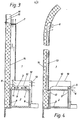
- a railroad car - of which only the area of a compartment 1 is shown - is provided with an air conditioning or heating system, not shown, which supplies heated or air-conditioned basic air to compartment 1 via a basic air duct 2.
- an air conditioning or heating system not shown, which supplies heated or air-conditioned basic air to compartment 1 via a basic air duct 2.
- a separate post-heating system 3 through which connecting air 4 flows through air emerging from the basic air duct 2 and in turn has outlets 5, 5 'which cooperate with outflow openings 6, 7, 8 in compartment 1.
- the air supplied in the basic air duct 2 is regulated by the air conditioning or heating system (not shown) in conjunction with its control with regard to the temperature and possibly also the amount of air to a pilot value which takes into account the external climatic conditions and, under certain circumstances, the occupation conditions in a pilot compartment.
- the post-heating system 3 which enables additional heating of the preheated or pre-air-conditioned basic air, is used for individual readjustment in each individual compartment.
- a housing 10 is placed on the basic air duct 2 provided with insulating walls 9, the interior of which receives the actual post-heating element 11 and is connected to the basic air duct 2 via the connection opening 4.
- the insulating walls 9 can for example consist of sheet metal walls with cork cladding; the housing 10 can be designed as a screwed or riveted sheet metal part.
- the basic air duct 2 has - as can be seen in particular from FIG. 4 - in addition to the connection opening 4 to the after-heating system 3, at least one separate outlet opening 12 which, bypassing the after-heating system 3, connects to the outflow opening 8 provided in the region of the upper window edge via an air duct 13 stands.
- the air duct 13 is integrated into the outer wall 14 of the car, but it would also be possible to attach the air channel 13 to the inside of the outer wall 14 of the car.
- the outflow opening 8 can, for example, extend between two air channels 13 drawn upwards on both sides of the window edges 15 over the entire area of the upper edge of the window, which enables outflow at a low speed and avoids any annoyance to the travelers.
- the basic air duct 2 running under the window 16 in the floor area thus supplies basic air via the air ducts 13 to the outflow opening 8 at the top, the temperature of this basic air permitting the heating or air conditioning required if the average occupancy of the compartment is assumed.
- the blowing out of reheated air required for changing the individual compartment climate takes place on the one hand at the outflow openings 6 under the seats 17 and on the other hand at the outflow opening 7 in the region of the lower window edge.
- the outflow openings 6 under the seats 17 are formed in a cover 18 of the basic air duct 2, which at the same time also serves to guide compartment air and the basic air duct 2 together with the afterheating system 3 covered by a distance.
- the outflow openings 6 are directly blown through by the behind, nozzle-shaped outlets 5 of the after-heating system 3, whereby - as can be seen in particular in FIG. 4 - a larger cross-section at the edge of the outflow openings 6 remains free due to the enlarged outlet openings 6 compared to the outlets 5, which consequently remains free of the negative pressure which forms there when post-heated air emerges from the post-heating system 3 acts as a backflow opening for compartment air into the interior of the cover 18.
- FIG. 1 and 3 show further backflow openings 19 in the area under the windows in the cover 18, which also allow compartment air to enter the inside of the cover 18.
- the compartment circulating air supplied via the return flow openings at the edge of the discharge opening 6 on the one hand and 19 on the other hand is mixed in the region of the outlets 5 ′ (FIG. 3) directed towards the discharge opening 7 with post-heated air emerging from the after-heating system 3 and blown out via the outflow opening 7 at the bottom edge of the window .
- This means that the critical window area is provided with an increased amount of heated air, especially when the outside temperature is low and when it is in heating mode, which increases travel comfort.
- FIG. 1 also folding tables 20, a waste container 21 and parts of the adjustment mechanism 22 for the seats 17 are shown; these parts are omitted in the other figures for the sake of simplicity.
Landscapes
- Engineering & Computer Science (AREA)
- Mechanical Engineering (AREA)
- Air-Conditioning For Vehicles (AREA)
- Coating Apparatus (AREA)
Applications Claiming Priority (2)
| Application Number | Priority Date | Filing Date | Title |
|---|---|---|---|
| AT0244984A AT382566B (de) | 1984-07-27 | 1984-07-27 | Eisenbahnwagen mit einer heiz- bzw. klimaanlage |
| AT2449/84 | 1984-07-27 |
Publications (3)
| Publication Number | Publication Date |
|---|---|
| EP0169833A2 true EP0169833A2 (fr) | 1986-01-29 |
| EP0169833A3 EP0169833A3 (en) | 1987-06-10 |
| EP0169833B1 EP0169833B1 (fr) | 1990-09-26 |
Family
ID=3534552
Family Applications (1)
| Application Number | Title | Priority Date | Filing Date |
|---|---|---|---|
| EP19850890163 Expired - Lifetime EP0169833B1 (fr) | 1984-07-27 | 1985-07-23 | Voiture ferroviaire avec installation de chauffage et de climatisation |
Country Status (6)
| Country | Link |
|---|---|
| EP (1) | EP0169833B1 (fr) |
| AT (1) | AT382566B (fr) |
| DE (1) | DE3579864D1 (fr) |
| ES (1) | ES8608422A1 (fr) |
| TR (1) | TR22910A (fr) |
| YU (1) | YU44893B (fr) |
Cited By (3)
| Publication number | Priority date | Publication date | Assignee | Title |
|---|---|---|---|---|
| DE4430075A1 (de) * | 1994-08-25 | 1996-02-29 | Abb Patent Gmbh | Modulares Seitenwandverkleidungssystem für einen Reisezugwagen |
| AT402722B (de) * | 1993-02-12 | 1997-08-25 | Friedmann Kg Alex | Verfahren zur klimatisierung und klimaanlage eines fahrzeuges, insbesondere eines schienenfahrzeuges |
| WO2016016049A1 (fr) * | 2014-08-01 | 2016-02-04 | Siemens Aktiengesellschaft | Véhicule, en particulier véhicule sur rails, équipé d'un dispositif de climatisation |
Families Citing this family (1)
| Publication number | Priority date | Publication date | Assignee | Title |
|---|---|---|---|---|
| AT395136B (de) * | 1987-12-01 | 1992-09-25 | Friedmann Kg Alex | Eisenbahnwagen mit einer heiz- bzw. klimaanlage |
Family Cites Families (4)
| Publication number | Priority date | Publication date | Assignee | Title |
|---|---|---|---|---|
| DE2308839B2 (de) * | 1972-03-07 | 1976-07-01 | Alex. Friedmann Kg, Wien | Einkanal-klimaanlage fuer schienenfahrzeuge |
| AT334417B (de) * | 1975-04-14 | 1976-01-10 | Friedmann Kg Alex | Einkanal-klimaanlage fur schienenfahrzeuge |
| ZA771500B (en) * | 1977-03-11 | 1978-06-28 | Ventline Mfg Ltd | Improvements in or relating to air conditioning |
| DE2851046A1 (de) * | 1978-11-25 | 1980-06-04 | Walter Ing Grad Hirsch | Luftauslassvorrichtung fuer raumklimatisierungs- und belueftungsanlagen |
-
1984
- 1984-07-27 AT AT0244984A patent/AT382566B/de not_active IP Right Cessation
-
1985
- 1985-07-19 YU YU118885A patent/YU44893B/xx unknown
- 1985-07-23 DE DE8585890163T patent/DE3579864D1/de not_active Expired - Lifetime
- 1985-07-23 EP EP19850890163 patent/EP0169833B1/fr not_active Expired - Lifetime
- 1985-07-25 TR TR3345185A patent/TR22910A/xx unknown
- 1985-07-26 ES ES545586A patent/ES8608422A1/es not_active Expired
Cited By (3)
| Publication number | Priority date | Publication date | Assignee | Title |
|---|---|---|---|---|
| AT402722B (de) * | 1993-02-12 | 1997-08-25 | Friedmann Kg Alex | Verfahren zur klimatisierung und klimaanlage eines fahrzeuges, insbesondere eines schienenfahrzeuges |
| DE4430075A1 (de) * | 1994-08-25 | 1996-02-29 | Abb Patent Gmbh | Modulares Seitenwandverkleidungssystem für einen Reisezugwagen |
| WO2016016049A1 (fr) * | 2014-08-01 | 2016-02-04 | Siemens Aktiengesellschaft | Véhicule, en particulier véhicule sur rails, équipé d'un dispositif de climatisation |
Also Published As
| Publication number | Publication date |
|---|---|
| ES545586A0 (es) | 1986-06-16 |
| YU44893B (en) | 1991-04-30 |
| EP0169833A3 (en) | 1987-06-10 |
| ATA244984A (de) | 1986-08-15 |
| DE3579864D1 (de) | 1990-10-31 |
| YU118885A (en) | 1989-02-28 |
| AT382566B (de) | 1987-03-10 |
| ES8608422A1 (es) | 1986-06-16 |
| EP0169833B1 (fr) | 1990-09-26 |
| TR22910A (tr) | 1988-10-15 |
Similar Documents
| Publication | Publication Date | Title |
|---|---|---|
| DE102018130048A1 (de) | Luftausströmer | |
| DE3002134A1 (de) | Heizungs- und belueftungseinrichtung fuer einen kraftwagen | |
| DE2835021A1 (de) | Heizungs- und belueftungsanlage, insbesondere fuer den fahrgastraum eines kraftfahrzeugs | |
| DE69319313T2 (de) | Vorrichtung für die Heizung, Lüftung und/oder Klimatisierung eines Fahrzeuginnenraumes | |
| DE102007005050A1 (de) | Verfahren zur Klimatisierung eines Fahrzeugs | |
| EP0354163A1 (fr) | Dispositif pour chauffer l'intérieur d'un véhicule automobile | |
| DE102007019382A1 (de) | Kraftfahrzeug-Klimaanlage | |
| DE10039791B4 (de) | Cabriolet | |
| EP0169833B1 (fr) | Voiture ferroviaire avec installation de chauffage et de climatisation | |
| DE19515836B4 (de) | Heizungs- und Belüftungsvorrichtung für Innenräume von Fahrzeugen | |
| DE10209074A1 (de) | Belüftungseinrichtung | |
| DE19941618B4 (de) | Vorrichtung zum Belüften des Innenraumes eines Kraftfahrzeuges | |
| DE1251172B (fr) | ||
| DE2701816A1 (de) | Luftausstroemer, insbesondere fuer den innenraum eines fahrzeugs | |
| EP0298952B1 (fr) | Cabine de conduite de véhicule ferroviaire | |
| DE4428955A1 (de) | Führerraumkabine für ein Schienenfahrzeug | |
| EP0155256B1 (fr) | Voiture de chemin de fer avec dispositif de chauffage et de climatisation | |
| DE2634715C3 (de) | Omnibus mit einer Heizungs- und/oder Belüftungseinrichtung | |
| DE825806C (de) | Heizungs- und Belueftungsanlage fuer Grossraumfahrzeuge, insbesondere fuer Omnibusse, Triebwagen u. dgl. | |
| DE2613608B2 (de) | Einkanal-Klimaanlage für Schienenfahrzeuge | |
| AT244382B (de) | Einrichtung zur Regelung der Temperatur in Fahrgasträumen von Fahrzeugen, insbesondere Schienenfahrzeugen | |
| DE1109549B (de) | Be- und Entlueftung fuer den Fahrgastraum von Kraftfahrzeugen | |
| AT395136B (de) | Eisenbahnwagen mit einer heiz- bzw. klimaanlage | |
| DE9114112U1 (de) | Einrichtung zur Zuführung konditionierter Luft in Reisezugwagen | |
| DE7440007U (de) | Luftführungskanal für die Klimatisierung von Schienenfahrzeugen |
Legal Events
| Date | Code | Title | Description |
|---|---|---|---|
| PUAI | Public reference made under article 153(3) epc to a published international application that has entered the european phase |
Free format text: ORIGINAL CODE: 0009012 |
|
| ITCL | It: translation for ep claims filed |
Representative=s name: MODIANO & ASSOCIATI S.R.L. |
|
| AK | Designated contracting states |
Designated state(s): BE DE FR IT |
|
| EL | Fr: translation of claims filed | ||
| PUAL | Search report despatched |
Free format text: ORIGINAL CODE: 0009013 |
|
| AK | Designated contracting states |
Kind code of ref document: A3 Designated state(s): BE DE FR IT |
|
| 17P | Request for examination filed |
Effective date: 19870930 |
|
| 17Q | First examination report despatched |
Effective date: 19890228 |
|
| GRAA | (expected) grant |
Free format text: ORIGINAL CODE: 0009210 |
|
| AK | Designated contracting states |
Kind code of ref document: B1 Designated state(s): BE DE FR IT |
|
| REF | Corresponds to: |
Ref document number: 3579864 Country of ref document: DE Date of ref document: 19901031 |
|
| ITF | It: translation for a ep patent filed | ||
| ET | Fr: translation filed | ||
| PLBE | No opposition filed within time limit |
Free format text: ORIGINAL CODE: 0009261 |
|
| STAA | Information on the status of an ep patent application or granted ep patent |
Free format text: STATUS: NO OPPOSITION FILED WITHIN TIME LIMIT |
|
| ITTA | It: last paid annual fee | ||
| 26N | No opposition filed | ||
| PGFP | Annual fee paid to national office [announced via postgrant information from national office to epo] |
Ref country code: BE Payment date: 19940714 Year of fee payment: 10 |
|
| PGFP | Annual fee paid to national office [announced via postgrant information from national office to epo] |
Ref country code: FR Payment date: 19940725 Year of fee payment: 10 |
|
| PGFP | Annual fee paid to national office [announced via postgrant information from national office to epo] |
Ref country code: DE Payment date: 19940915 Year of fee payment: 10 |
|
| PG25 | Lapsed in a contracting state [announced via postgrant information from national office to epo] |
Ref country code: BE Effective date: 19950731 |
|
| BERE | Be: lapsed |
Owner name: ALEX. FRIEDMANN K.G. Effective date: 19950731 |
|
| PG25 | Lapsed in a contracting state [announced via postgrant information from national office to epo] |
Ref country code: DE Effective date: 19960402 |
|
| PG25 | Lapsed in a contracting state [announced via postgrant information from national office to epo] |
Ref country code: FR Effective date: 19960430 |
|
| REG | Reference to a national code |
Ref country code: FR Ref legal event code: ST |
|
| REG | Reference to a national code |
Ref country code: FR Ref legal event code: ST |
|
| REG | Reference to a national code |
Ref country code: FR Ref legal event code: ST |