EP0169210B1 - Dynamische ecl-schaltung zum schalten von lasten mit bedeutender kapazität - Google Patents
Dynamische ecl-schaltung zum schalten von lasten mit bedeutender kapazität Download PDFInfo
- Publication number
- EP0169210B1 EP0169210B1 EP84903913A EP84903913A EP0169210B1 EP 0169210 B1 EP0169210 B1 EP 0169210B1 EP 84903913 A EP84903913 A EP 84903913A EP 84903913 A EP84903913 A EP 84903913A EP 0169210 B1 EP0169210 B1 EP 0169210B1
- Authority
- EP
- European Patent Office
- Prior art keywords
- current source
- source transistor
- base
- transistor
- emitter
- Prior art date
- Legal status (The legal status is an assumption and is not a legal conclusion. Google has not performed a legal analysis and makes no representation as to the accuracy of the status listed.)
- Expired - Lifetime
Links
- 239000003990 capacitor Substances 0.000 claims abstract description 42
- 230000000295 complement effect Effects 0.000 claims abstract description 38
- 230000001052 transient effect Effects 0.000 claims abstract description 16
- 230000003071 parasitic effect Effects 0.000 claims description 3
- 238000002955 isolation Methods 0.000 claims 1
- 230000007704 transition Effects 0.000 abstract description 36
- 230000008859 change Effects 0.000 abstract description 4
- 230000004075 alteration Effects 0.000 abstract 1
- 238000010586 diagram Methods 0.000 description 12
- 238000013459 approach Methods 0.000 description 7
- 230000008901 benefit Effects 0.000 description 6
- 238000013461 design Methods 0.000 description 6
- 230000009977 dual effect Effects 0.000 description 4
- 230000000630 rising effect Effects 0.000 description 4
- 230000008878 coupling Effects 0.000 description 2
- 238000010168 coupling process Methods 0.000 description 2
- 238000005859 coupling reaction Methods 0.000 description 2
- 230000003247 decreasing effect Effects 0.000 description 2
- 230000000694 effects Effects 0.000 description 2
- 238000000034 method Methods 0.000 description 2
- 238000012986 modification Methods 0.000 description 2
- 230000004048 modification Effects 0.000 description 2
- 238000003491 array Methods 0.000 description 1
- 230000015556 catabolic process Effects 0.000 description 1
- 238000006243 chemical reaction Methods 0.000 description 1
- 230000001186 cumulative effect Effects 0.000 description 1
- 238000006731 degradation reaction Methods 0.000 description 1
- 230000001934 delay Effects 0.000 description 1
- 230000006872 improvement Effects 0.000 description 1
- 230000010354 integration Effects 0.000 description 1
- 230000001788 irregular Effects 0.000 description 1
- 238000004519 manufacturing process Methods 0.000 description 1
- 239000002184 metal Substances 0.000 description 1
- 231100000989 no adverse effect Toxicity 0.000 description 1
- 238000012545 processing Methods 0.000 description 1
- 238000005086 pumping Methods 0.000 description 1
- 238000012358 sourcing Methods 0.000 description 1
Images
Classifications
-
- H—ELECTRICITY
- H03—ELECTRONIC CIRCUITRY
- H03K—PULSE TECHNIQUE
- H03K19/00—Logic circuits, i.e. having at least two inputs acting on one output; Inverting circuits
- H03K19/01—Modifications for accelerating switching
- H03K19/013—Modifications for accelerating switching in bipolar transistor circuits
- H03K19/0136—Modifications for accelerating switching in bipolar transistor circuits by means of a pull-up or down element
-
- H—ELECTRICITY
- H03—ELECTRONIC CIRCUITRY
- H03K—PULSE TECHNIQUE
- H03K19/00—Logic circuits, i.e. having at least two inputs acting on one output; Inverting circuits
- H03K19/02—Logic circuits, i.e. having at least two inputs acting on one output; Inverting circuits using specified components
- H03K19/08—Logic circuits, i.e. having at least two inputs acting on one output; Inverting circuits using specified components using semiconductor devices
- H03K19/082—Logic circuits, i.e. having at least two inputs acting on one output; Inverting circuits using specified components using semiconductor devices using bipolar transistors
- H03K19/086—Emitter coupled logic
- H03K19/0866—Stacked emitter coupled logic
Definitions
- This invention relates to a high speed ECL gate circuit and, more particularly, relates to a dynamic ECL gate circuit for driving line loads having significant capacitance.
- ECL emitter-coupled logic
- ECL Error Correction Code
- Integrated Circuits Design Principles and Fabrication , R. N. Warner, Jr., ed. McGraw-Hill (1965), Sec. 5-10, pp. 156-159.
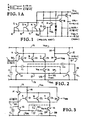
- the most common ECL design is a multiple input OR/NOR gate.
- Such a gate is a versatile logic building block since it has complementary outputs.
- ECL gates have an inherently low gate propagation delay, they have relatively slow rise and fall times.
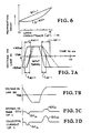
- the gate propagation delay will be impacted with heavy capacitive loading; as shown in Fig. 6, for conventional ECL, as the load capacitance of the output lines increases, the propagation delay time increases linearly.
- the present invention provides an ECL gate circuit having one or more input transistors, a reference voltage transistor an output line the output line having associated therewith an emitter follower for pulling up the output line and a current sources transistor for pulling down the output line characterised in that the base of the current source transistor is connected to a control voltage, and a capacitor is connected between the base of said current source transistor and a circuit point having a logic level which is complementary to the logic level of the output line pulled down by said current source transistor, to superimpose a transient increase of potential on said base of said current source transistor when said circuit point goes from a low to a high logic level.
- the present invention provides an ECL gate circuit having multiple input transistors, a reference voltage transistor, the complement to output lines each output line having associated therewith a respective emitter follower for pulling up the output line and a current source transistor for forming the emitter resistor of the emitter follower pulling down the output line, characterised in that the bases of the two current source transistors are connected to a control voltage, and respective capacitor are connected between the base of each said current source transistors and a respective circuit point having a logic level which is complementary to the logic level of the output line pulled down by the current source transistor, to superimpose a transient increase of potential on the base of that current source transistor when the circuit point goes from a low to a high logic level.
- An ECL circuit is provided which is adapted to drive loads having significant capacitance.
- a single level or multiple level ECL gate such as an OR/NOR gate is provided with ancillary capacitors between the bases of the current source transistors and circuit points within the gate circuit having complementary logic levels. As logic levels shift, the occurrence of a transition in the complementary level will produce a transient current through the ancillary capacitor thereby momentarily altering the voltage on the base of the associated current source transistor. When the logic level on the collector of a current source transistor is experiencing a high-to-low transition the base voltage will be momentarily increased due to this transient thereby increasing the current sunk through the current source transistor and speeding up the high-to-low transition time.
- the standard building block for ECL logic circuitry is the OR/NOR circuit shown in Fig. 1. Briefly, an application of a high logic signal to the terminals A, B, or C which are the bases, respectively, of bipolar transistors 2, 3 and 4, will result in a high OR output on the emitter of noninverting output transistor 9 and a low NOR output on the emitter of inverting output transistor 8.
- the logical operation of the OR/NOR gate circuit is symbolized by the logic diagram shown in Fig. 1a.
- the operation of this conventional ECL gate is described in detail, for example in L. S. Garrett, "ECL and MOS Devices", in Digital Logic Gates , McGraw-Hill, pp. 31-38 (1978).
- Transistor 15 is an emitter follower (as is its complementary counterpart transistor 14) that provides current to OR output line 31 to produce a low-to-high transition whenever a high input is provided on terminals A, B or C to transistors 21, 22 or 23.
- Emitter follower 15 is a low impedance device.
- transistor 11 is a current source (as is its complementary counterpart 10) and is current limited.
- current source 11 When a high-to-low transition is to occur on OR output line 31 current source 11 must sink the charge C L on line 31. Though continuous, the current through current source transistor 11 is finite and limited. Without the assistance provided by the present invention or without assistance from some other technique as discussed in the Background of the Invention section, the unloading of line charge through current source transistor 11 will take as long as t d-- , shown in Fig. 7a.
- the dynamic ECL circuit of the present invention utilizes on-chip capacitances to provide a transient boost to the current carrying capabilities of the load current source transistors 10 and 11 in ECL gate circuits.
- the transient boost is generated by connecting a capacitor between the base of the current source transistor and a point in the circuit which carries a complementary logic level. As shown in Figs. 7a, 7b, 7c and 7d, when the logic level on OR output line 31 is experiencing a low-to-high transition the complementary logic level on NOR output line 30 is experiencing a downgoing transition.
- a change in voltage ( V lh for the low-to-high transition associated with the collector of the current source transistor and V hl for the high-to-low transition) occurs on the base of the current source transistor only when the complementary logic level is experiencing a change. This is due to the characteristic of capacitors that a differential voltage is experienced on one side only when the voltage is changing on the other side.
- Once equilibrium is reached i.e. once the complementary logic level is reached (whether a high level or a low level) there will be no further contribution to the voltage on the base of the current source transistor until the next shift in the complementary logic level.
- This dynamic approach is contrasted to the steady state or DC approach discussed in the Background section and disclosed in A.W.
- the effect on the current source transistor can be troublesome if the driving logic, e.g. the input logic on terminals A, B, and C, is applied at irregular intervals to that some periods between logic swings are of relatively long duration.
- the dynamic ECL gate of the present invention the dynamic impact on the current source transistor is quantized so that no adverse effect occurs if the driving logic appears irregularly.
- Fig. 2 One embodiment of the dynamic ECL circuit of the present invention is shown in Fig. 2. It is shown as a conventional OR/NOR ECL gate circuit modified in accordance with the present invention. Figs. 2-4 share common elements and where common devices and functions are indicated, identical numbers are used.
- the function of the ECL gate circuit, as described above, is to accept logic level inputs on the base terminals A, B and C of transistors 21, 22 and 23 and to provide a logical OR output on line 31 along with a logical NOR output on line 30.
- the embodiments of Figs. 2-4 utilize single level logic, i.e. a single voltage level in the input and output. On the other hand, as described subsequently, multiple level logic is possible and a dual level logic scheme is shown in Fig. 5. In Fig. 5,
- transistor 11 appropriately called a current source transistor, serves to pull down the OR output line 31, while transistor 15, called an emitter follower, serves to pull up the OR output line 31.
- current source transistor 10 serves to pull down NOR output line 30, while emitter follower 14 serves to pull up NOR output line 31.
- pullup, rising, upgoing and low-to-high are synonyms and the terms pulldown, downgoing, falling and high-to-low are synonyms.
- a capacitive load 18 of capacitance C L on OR output line 31 and a capacitive load 17 of capacitance C L on NOR output line 30 may be large, on the order of 1-10 pF.
- the present invention assists in taking charge from these capacitances when the line levels are high and assists in charging these capacitances when the line levels are low.
- an OR output logic level is produced on line 31 (even dotted line) and a NOR logic level on line 30 (Fig. 7b) following the impression of a logical input (heavy solid line) on base terminals A, B or C of transistors 21, 22 or 23.
- the upgoing signal on line 31 and the complementary downgoing signal on line 30 follow the input by a short time delay.
- the OR output logic level is advanced as shown by the light solid line. Rise times in conventional ECL gate circuits are typically on the order of 1-2 ns whereas fall times are typically 2-4 ns.
- rise and fall times are materially reduced by the use of capacitors between the bases of current output transistors and the complementary logic levels.
- the rise time is reduced from t d++ to t dd++ and the fall time is reduced from t d-- to t dd-- .
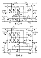
- the capacitor C2 is connected between the base of current source transistor 10 and the OR output line 31.
- the capacitor C1 is connected between the base of current source transistor 11 and the NOR output line 30 to take advantage of the complementary logic level available. Either capacitor may be used alone or the two capacitors may be used together as shown, depending on whether there is a circuit requirement for an improved fall time on either or both the OR output or the NOR output.
- the bandgap reference voltage V CS is a stable tracking voltage available on all ECL chips. See A.H. Seidman, Integrated Circuits Applications Handbook , pp. 498-499 (1983). This reference voltage is used for controlling the ECL current through transistor 16.
- a stable bias voltage V CSL is impressed on terminal 32 to provide the bias levels on the bases of the current source transistors 10 and 11.
- V CSL is coupled through isolating resistor 29 to the base of current source transistor 11 and is coupled through resistor 27 to the base of current source transistor 10. These resistors have large values on the order of 40k ohms to isolate the base for AC coupling with capacitors C1 and C2.
- FIG. 4 Another embodiment of the present invention is shown in Fig. 4.
- the base of current source transistor 10 is connected through capacitor C2 to the base of emitter follower 15 and the base of current source transistor 11 is connected through capacitor C1 to the base of emitter follower 14.
- the nature of operation of emitter follower 14 will be that it will be conductive when NOR output transistor 10 is conductive.
- Emitter follower 14 will have become conductive to supply current to support the low-to-high transition on NOR output line 30.
- the base of emitter follower transistor 14 will go to a high level thereby producing a momentary increase in the voltage on the base of transistor 11, ⁇ V hl , as shown in Fig. 7c. This will pull down the output at line 31 sooner than it would have come down by normal means.
- the benefit is seen as the difference between t d-- and t dd-- shown in Fig. 7a.
- a comparable benefit for similar reasons is obtained on low-to-high transitions for OR output line 31.
- comparable benefits are obtained for both downgoing and rising transitions on NOR output line 31.
- the base of current source transistor 10 is shown as being connected through capacitor C1 to the collector of current source transistor 16 and to the common emitters of transistors 21, 22 and 23. This connection is possible since when a high-to-low transition is to take place on NOR output line 30, there will be current flowing through at least one of the transistors 21, 22 and 23 and thence through transistor 16 to low voltage level V ss so that the collector of transistor 16 is rising while NOR output line 30 is falling; hence the collector of transistor 16 serves as a complementary logic level.
- the capacitors C1 and C1 shown in Figs. 2-5 are of small value on the order of 0.05 - 0.1 pf. They are obtained, for example, by integrating extra bases to the load current source transistor collectors, i.e. to the collector of current source transistor 10 or to the collector of current source transistor 11, shown in Fig. 2, or to the collector of input current source transistor 16, shown in Fig. 3. Such capacitors would be parasitic capacitors. These small capacitances can also be obtained by integrating extra emitters onto current source transistors 10 and 11 and connecting these emitters to the complementary circuit points, i.e. to the collector of current source transistor 10, to the collector of current source transistor 11, etc.
- ECL gate circuits Multiple level logic is now common for ECL gate circuits.
- the dynamic ECL gate circuit approach of the present invention is applicable to such schemes since they all contain complementary logic levels and have current source transistors which are current limited.
- dynamic charge pumping means using a capacitor as described above, a transient increase or decrease in the current through a given current source transistor is obtained to speed up the transition times on the output line associated with the transistor.
- Fig. 5 in a dual level logic scheme there will be two voltage levels or more precisely voltage ranges on OR output line 31 which will signify two discrete logic states. The first level will be uniquely accessible only on line 33; the second will be accessible on line 31.
- NOR output line 30 there will be two voltage ranges on NOR output line 30 which will signify different logic states with the first logic level only being accessible on line 34; the second will be accessible on line 30.
- additional input transistors 38, 39 and 40 are provided so that additional logic inputs A', B' and C' may be provided.
- An additional reference voltage V BB 1 is provided on the base of transistor 32 which has a common emitter coupling with the additional input transistors 38, 39 and 40.
- Transistor 32 provides a base drive for emitter follower 15 in accordance with the sense of the second logic levels.
- the method and apparatus of the present invention functions as described with respect to single level logic.
- capacitor C1 may be connected between the base of current source transistor 11 and the base of emitter follower 14.
- capacitor C2 may be connected between the base of current source transistor 10 and the collector of current source transistor 11.
Landscapes
- Engineering & Computer Science (AREA)
- Physics & Mathematics (AREA)
- Computer Hardware Design (AREA)
- Computing Systems (AREA)
- General Engineering & Computer Science (AREA)
- Mathematical Physics (AREA)
- Power Engineering (AREA)
- Logic Circuits (AREA)
Claims (14)
- ECL-Gatterschaltung mit einem oder mehreren Eingangstransistoren (21, 22, 23), einem Referenzspannungstransistor (24), einer Ausgangsleitung (31), wobei die Ausgangsleitung (31) mit einem Emitterfolger (15) zum Heraufziehen der Ausgangsleitung (31) verbunden ist, und einem Stromquellentransistor (11) zum Herabziehen der Ausgangsleitung (31),
dadurch gekennzeichnet, daß die Basis des Stromquellentransistors (11) mit einer konstanten Steuerspannung (VCSL) verbunden ist, und ein Kondensator (C1) zwischen der Basis des Stromquellentransistors (11) und einem Schaltungspunkt verbunden ist, der einen logischen Pegel aufweist, der zu dem logischen Pegel der durch den Stromquellentransistor (11) herabgezogenen Ausgangsleitung (31) komplementär ist, um einen Übergangsanstieg des Potentials an der Basis des Stromquellentransistors zu überlagern, wenn der Schaltungspunkt von einem logischen Low-Pegel zu einem logischen High-Pegel übergeht. - ECL-Gatterschaltung mit einem oder mehreren Eingangstransistoren (21, 22, 23), einem Referenzspannungstransistor (24), zwei Komplementär-Ausgangsleitungen (30,31), wobei jede der Ausgangsleitungen (30,31) mit einem jeweiligen Emitterfolger (14,15) zum Heraufziehen der Ausgangsleitung verbunden ist, und einem Stromquellentransistor (10,11) zum Bilden des Emitterwiderstands des Emitterfolgers zum Herunterziehen der Ausgangsleitung,
dadurch gekennzeichnet, daß die Basen der beiden Stromquellentransistoren (10,11) mit einer konstanten Steuerspannung (VCSL) verbunden sind, und jeweilige Kondensatoren (C1,C2) zwischen der Basis jedes Stromquellentransistors und einem jeweiligen Schaltungspunkt verbunden sind, der einen logischen Pegel aufweist, der zu dem logischen Pegel der durch den Stromquellentransistor herabgezogenen Ausgangsleitung komplementär ist, um einen Übergangsanstieg des Potentials an der Basis dieses Stromquellentransistors zu überlagern, wenn der Schaltungspunkt von einem logischen Low-Pegel zu einem logischen High-Pegel übergeht. - ECL-Gatterschaltung nach Anspruch 1 oder 2, dadurch gekennzeichnet, daß der oder jeder Kondensator (C1, C2) einen parasitären Kondensator aufweist.
- ECL-Gatterschaltung nach Anspruch 3, dadurch gekennzeichnet, daß der oder jeder Stromquellentransistor (10, 11) in enger physikalischer Nähe zu dem betreffenden Schaltungspunkt mit einem komplementären logischen Pegel ausgebildet ist, um so den parasitären Kondensator (C1, C2) zu bilden.
- ECL-Gatterschaltung nach Anspruch 1 oder 2, dadurch gekennzeichnet, daß der oder jeder Kondensator (C1, C2) einen zusätzlichen Emitter des Stromquellentransistors (10,11) umfaßt, wobei der zusätzliche Emitter mit dem einen komplementären logischen Pegel aufweisenden Schaltungspunkt verbunden ist.
- ECL-Gatterschaltung nach Anspruch 1 oder 2, dadurch gekennzeichnet, daß der oder jeder Kondensator (C1, C2) einen integrierten Kondensator aufweist.
- ECL-Gatterschaltung nach Anspruch 1 oder 2, dadurch gekennzeichnet, daß der oder jeder Kondensator (C1, C2) zwischen seinem jeweiligen Stromquellentransistor (10, 11) und der Basis des betreffenden Emitterfolgers verbunden ist.
- ECL-Gatterschaltung nach Anspruch 2, dadurch gekennzeichnet, daß jeder Kondensator (C1, C2) zwischen seinem jeweiligen Stromquellentransistor (10, 11) und dem Kollektor des anderen Stromquellentransistors (10, 11) verbunden ist.
- ECL-Gatterschaltung nach einem der Ansprüche 1 bis 8, dadurch gekennzeichnet, daß die Kollektoren mehrerer Eingangstransistoren (21, 22, 23) über einen Widerstand (19) mit einer Speisespannung VCC und ihre Emitter miteinander verbunden sind, wobei logische Eingangssignale zum ECL-Gatter den Basen der Eingangstransistoren (21, 22, 23) zugeführt werden;
daß eine Referenzspannung VBB an der Basis des Referenztransistors (24) anliegt, der Emitter des Referenztransistors (24) mit den Emittern der mehreren Eingangstransistoren (21, 22, 23), und der Kollektor des Referenztransistors (24) über einen Widerstand (20) mit der Speisespannung VCC verbunden ist;
daß der oder jeder Stromquellentransistor (10, 11) einen mit einer jeweiligen Ausgangsleitung (30, 31) verbundenen Kollektor aufweist, wobei der Emitter des oder jedes Stromquellentransistors (10, 11) mit Masse (13) verbunden ist;
daß der oder jeder Emitterfolger (14, 15) einen mit der Speisespannung VCC verbundenen Kollektor, einen mit einer jeweiligen Ausgangsleitung (30, 31) verbundenen Emitter und eine mit dem Kollektor des Referenztransistors (24) oder eines Eingangstransistors (21, 22, 23) verbundene Basis aufweist;
daß ein Haupt-Stromquellentransistor (16) einen mit der gemeinsamen Emitterverbindung der mehreren Eingangstransistoren (21, 22, 23) verbundenen Kollektor und einen über einen Widerstand (28) mit einem Niedrigpotential (13) verbundenen Emitter aufweist, wobei die Basis des Haupt-Stromquellentransistors mit einer Referenzspannung VCS verbunden ist. - ECL-Gatterschaltung nach einem der Ansprüche 1-9, dadurch gekennzeichnet, daß eine Bias-Schaltungseinrichtung (28) zum Anlegen einer Biasspannung an der Basis des oder aller Stromquellentransistoren (10, 11) vorgesehen ist.
- ECL-Gatterschaltung nach Anspruch 10, dadurch gekennzeichnet, daß ein Isolierwiderstand (27, 29) zwischen der Bias-Schaltungseinrichtung (28) und der Basis des oder aller Stromquellentransistoren (10, 11) vorgesehen ist, um an der Basis Übergangsspannung zu isolieren.
- ECL-Gatterschaltung nach Anspruch 9, dadurch gekennzeichnet, daß die Referenzspannung an der Basis des Haupt-Stromquellentransistors (16) die Bandabstandsreferenzspannung ist.
- ECL-Gatterschaltung nach Anspruch 9, in Abhängigkeit von Anspruch 1, dadurch gekennzeichnet, daß der Kondensator (C2) zwischen der Basis des Stromquellentransistors (10) und dem Kollektor eines Haupt-Stromquellentransistors (16) verbunden ist, wobei der Kollektor des Haupt-Stromquellentransistors (16) mit der gemeinsamen Emitterverbindung der mehreren Eingangstransistoren (21,22,23) und der Emitter über einen Widerstand (28) mit einer Niedrigpotential (13) verbunden ist, wobei die Basis des Hauptstromquellentransistors mit einer Referenzspannung VCS verbunden ist.
- ECL-Gatterschaltung nach Anspruch 9, in Abhängigkeit von Anspruch 1, dadurch gekennzeichnet, daß der Kondensator (C1) zwischen der Basis des Stromquellentransistors (10) und dem Kollektor eines Haupt-Stromquellentransistors (16) verbunden ist.
Priority Applications (1)
| Application Number | Priority Date | Filing Date | Title |
|---|---|---|---|
| AT84903913T ATE68645T1 (de) | 1983-11-09 | 1984-10-22 | Dynamische ecl-schaltung zum schalten von lasten mit bedeutender kapazitaet. |
Applications Claiming Priority (2)
| Application Number | Priority Date | Filing Date | Title |
|---|---|---|---|
| US06/550,528 US4539493A (en) | 1983-11-09 | 1983-11-09 | Dynamic ECL circuit adapted to drive loads having significant capacitance |
| US550528 | 1990-07-10 |
Publications (3)
| Publication Number | Publication Date |
|---|---|
| EP0169210A1 EP0169210A1 (de) | 1986-01-29 |
| EP0169210A4 EP0169210A4 (de) | 1987-01-22 |
| EP0169210B1 true EP0169210B1 (de) | 1991-10-16 |
Family
ID=24197548
Family Applications (1)
| Application Number | Title | Priority Date | Filing Date |
|---|---|---|---|
| EP84903913A Expired - Lifetime EP0169210B1 (de) | 1983-11-09 | 1984-10-22 | Dynamische ecl-schaltung zum schalten von lasten mit bedeutender kapazität |
Country Status (5)
| Country | Link |
|---|---|
| US (1) | US4539493A (de) |
| EP (1) | EP0169210B1 (de) |
| JP (1) | JPS61500400A (de) |
| DE (1) | DE3485182D1 (de) |
| WO (1) | WO1985002306A1 (de) |
Families Citing this family (31)
| Publication number | Priority date | Publication date | Assignee | Title |
|---|---|---|---|---|
| DE3217512A1 (de) * | 1982-05-10 | 1983-11-10 | Siemens AG, 1000 Berlin und 8000 München | Schaltungsanordnung zur pegelumsetzung |
| US4547881A (en) * | 1983-11-09 | 1985-10-15 | Advanced Micro Devices, Inc. | ECL Logic circuit with a circuit for dynamically switchable low drop current source |
| JPS6177424A (ja) * | 1984-09-25 | 1986-04-21 | Fujitsu Ltd | Ecl回路 |
| US4626709A (en) * | 1984-09-28 | 1986-12-02 | Advanced Micro Devices, Inc. | Dynamic push-pull for ECL |
| US4670673A (en) * | 1985-02-19 | 1987-06-02 | Advanced Micro Devices, Inc. | Multilevel differential ECL/CML gate circuit |
| JPS61274513A (ja) * | 1985-04-19 | 1986-12-04 | アドバンスト・マイクロ・デイバイシズ・インコ−ポレ−テツド | 論理レベル変換器 |
| US4682056A (en) * | 1985-10-16 | 1987-07-21 | International Business Machines Corporation | Switching circuit having low speed/power product |
| EP0219867B1 (de) * | 1985-10-23 | 1993-12-29 | Nec Corporation | Logische Schaltung |
| US4687953A (en) * | 1986-04-18 | 1987-08-18 | Advanced Micro Devices, Inc. | Dynamic ECL line driver circuit |
| JPS63302621A (ja) * | 1987-06-02 | 1988-12-09 | Fujitsu Ltd | 半導体集積回路 |
| JPS6424628A (en) * | 1987-07-21 | 1989-01-26 | Fujitsu Ltd | Emitter coupled logic circuit |
| US4926065A (en) * | 1987-11-17 | 1990-05-15 | Applied Micro Circuits Corporation | Method and apparatus for coupling an ECL output signal using a clamped capacitive bootstrap circuit |
| US4835420A (en) * | 1987-11-17 | 1989-05-30 | Applied Micro Circuits Corporation | Method and apparatus for signal level conversion with clamped capacitive bootstrap |
| US5027013A (en) * | 1987-11-17 | 1991-06-25 | Applied Micro Circuits Corporation | Method and apparatus for coupling an ECL output signal using a clamped capacitive bootstrap circuit |
| KR890016669A (ko) * | 1988-04-02 | 1989-11-29 | 미다 가쓰시게 | 반도체 집적회로 |
| JPH01259623A (ja) * | 1988-04-08 | 1989-10-17 | Toshiba Corp | 非飽和型論理回路 |
| US4980579A (en) * | 1988-08-29 | 1990-12-25 | Motorola, Inc. | ECL gate having dummy load for substantially reducing skew |
| JPH0738580B2 (ja) * | 1988-09-30 | 1995-04-26 | 日本電気株式会社 | エミッタ結合論理回路 |
| US4948991A (en) * | 1988-11-03 | 1990-08-14 | Motorola Inc. | Load controlled ECL transient driver |
| JPH03157015A (ja) * | 1989-08-25 | 1991-07-05 | Fujitsu Ltd | Ecl回路 |
| US5216296A (en) * | 1989-09-18 | 1993-06-01 | Fujitsu Limited | Logic circuit having sharper falling edge transition |
| JPH0666678B2 (ja) * | 1989-11-30 | 1994-08-24 | 株式会社東芝 | Ecl回路 |
| US5012128A (en) * | 1990-01-24 | 1991-04-30 | International Business Machines Corporation | High speed push-pull driver having current mirror pull-down |
| JPH0666679B2 (ja) * | 1990-01-31 | 1994-08-24 | 株式会社東芝 | Ecl論理回路 |
| US5087837A (en) * | 1990-08-06 | 1992-02-11 | North American Philips Corp., Signetics Div. | Electronic circuit with capacitively enhanced switching |
| US5321320A (en) * | 1992-08-03 | 1994-06-14 | Unisys Corporation | ECL driver with adjustable rise and fall times, and method therefor |
| US5274285A (en) * | 1992-09-01 | 1993-12-28 | International Business Machines Corporation | Enhanced differential current switch compensating upshift circuit |
| DE4324854C1 (de) * | 1993-07-23 | 1995-01-12 | Siemens Ag | Ausgangsstufe für digitale Stromschalter |
| US6204654B1 (en) * | 1999-01-29 | 2001-03-20 | Analog Devices, Inc. | Dynamically boosted current source circuit |
| US7116253B2 (en) * | 2003-08-05 | 2006-10-03 | Stmicroelectronics N.V. | Radio frequency digital-to-analog converter |
| US10892755B2 (en) * | 2018-02-27 | 2021-01-12 | Cognipower, Llc | Driver circuitry for fast, efficient state transitions |
Family Cites Families (13)
| Publication number | Priority date | Publication date | Assignee | Title |
|---|---|---|---|---|
| US3549899A (en) * | 1967-03-31 | 1970-12-22 | Rca Corp | Input and output emitter-follower cml circuitry |
| NL7010432A (de) * | 1970-07-15 | 1972-01-18 | ||
| CA1007308A (en) * | 1972-12-29 | 1977-03-22 | Jack A. Dorler | Cross-coupled capacitor for ac performance tuning |
| JPS50134356A (de) * | 1974-04-10 | 1975-10-24 | ||
| US3978347A (en) * | 1974-10-02 | 1976-08-31 | Motorola, Inc. | High band width emitter coupled logic gate |
| US4092551A (en) * | 1976-05-20 | 1978-05-30 | International Business Machines Corporation | A.C. powered speed up circuit |
| US4132906A (en) * | 1977-02-28 | 1979-01-02 | Motorola, Inc. | Circuit to improve rise time and/or reduce parasitic power supply spike current in bipolar transistor logic circuits |
| DE2751881A1 (de) * | 1977-11-21 | 1979-05-23 | Siemens Ag | Monolithische digitale halbleiterschaltung mit mehreren bipolartransistoren |
| US4449063A (en) * | 1979-08-29 | 1984-05-15 | Fujitsu Limited | Logic circuit with improved switching |
| US4289978A (en) * | 1979-10-05 | 1981-09-15 | International Business Machines Corp. | Complementary transistor inverting emitter follower circuit |
| US4347446A (en) * | 1979-12-10 | 1982-08-31 | Amdahl Corporation | Emitter coupled logic circuit with active pull-down |
| US4409498A (en) * | 1980-12-30 | 1983-10-11 | International Business Machines Corporation | Transient controlled current switch |
| DE3217512A1 (de) * | 1982-05-10 | 1983-11-10 | Siemens AG, 1000 Berlin und 8000 München | Schaltungsanordnung zur pegelumsetzung |
-
1983
- 1983-11-09 US US06/550,528 patent/US4539493A/en not_active Expired - Lifetime
-
1984
- 1984-10-22 JP JP59503967A patent/JPS61500400A/ja active Pending
- 1984-10-22 WO PCT/US1984/001712 patent/WO1985002306A1/en not_active Ceased
- 1984-10-22 EP EP84903913A patent/EP0169210B1/de not_active Expired - Lifetime
- 1984-10-22 DE DE8484903913T patent/DE3485182D1/de not_active Expired - Lifetime
Non-Patent Citations (2)
| Title |
|---|
| IBM Technical Disclosure Bulletin, vol. 19, no. 12, issued May 1977 (Armonk, New York), A. W. CHANG et al, "Complementary DRiver for Emitter-Coupled-Logic Gates" see pages 4614-5 * |
| IBM Technical Disclosure Bulletin, vol. 20, no. 9, issued February 1978 (Armonk, New York), M. Cases et al, "Emitter-Coupled Logic Totem-Pole Driver with Multiple Wired Logic Function Capability" see pages 3471-2 * |
Also Published As
| Publication number | Publication date |
|---|---|
| WO1985002306A1 (en) | 1985-05-23 |
| JPS61500400A (ja) | 1986-03-06 |
| DE3485182D1 (de) | 1991-11-21 |
| EP0169210A4 (de) | 1987-01-22 |
| US4539493A (en) | 1985-09-03 |
| EP0169210A1 (de) | 1986-01-29 |
Similar Documents
| Publication | Publication Date | Title |
|---|---|---|
| EP0169210B1 (de) | Dynamische ecl-schaltung zum schalten von lasten mit bedeutender kapazität | |
| US4628216A (en) | Merging of logic function circuits to ECL latch or flip-flop circuit | |
| US5365127A (en) | Circuit for conversion from CMOS voltage levels to shifted ECL voltage levels with process compensation | |
| US5017807A (en) | Output buffer having capacitive drive shunt for reduced noise | |
| JPH08223014A (ja) | 電力スイッチの貫通電流を減少させる比較器回路 | |
| WO2006016970A2 (en) | High speed integrated circuit | |
| US5132572A (en) | High-speed CMOS-to-ECL translator circuit | |
| KR900008052B1 (ko) | 반도체 집적회로 장치 | |
| US4689505A (en) | High speed bootstrapped CMOS driver | |
| JP2002198791A (ja) | 電源電圧以外の電圧を使用する集積回路用の出力ドライバ | |
| US4605871A (en) | Inverter function logic gate | |
| US5214317A (en) | CMOS to ECL translator with incorporated latch | |
| US6144218A (en) | High speed analog compensated input buffer | |
| US5561388A (en) | Semiconductor device having CMOS circuit and bipolar circuit mixed | |
| JP2909382B2 (ja) | 集積回路 | |
| EP0055341B1 (de) | Stromgesteuertes Gatter | |
| US6025792A (en) | Analog compensation circuitry for integrated circuit input/output circuitry | |
| US5059827A (en) | ECL circuit with low voltage/fast pull-down | |
| US3573489A (en) | High speed current-mode logic gate | |
| US5338980A (en) | Circuit for providing a high-speed logic transition | |
| US5389832A (en) | Capacitively cross-coupled DCS emitter-follower output stage | |
| EP0882265A1 (de) | Vorrichtung und verfahren für signalverarbeitung auf gtl-typenbussen | |
| US5406143A (en) | GTL to CMOS level signal converter, method and apparatus | |
| JPH0738581B2 (ja) | Ecl回路 | |
| US4725744A (en) | Input buffer circuit and logic circuit using the buffer circuit |
Legal Events
| Date | Code | Title | Description |
|---|---|---|---|
| PUAI | Public reference made under article 153(3) epc to a published international application that has entered the european phase |
Free format text: ORIGINAL CODE: 0009012 |
|
| 17P | Request for examination filed |
Effective date: 19850611 |
|
| AK | Designated contracting states |
Designated state(s): AT BE CH DE FR GB LI LU NL SE |
|
| A4 | Supplementary search report drawn up and despatched |
Effective date: 19870122 |
|
| 17Q | First examination report despatched |
Effective date: 19880225 |
|
| GRAA | (expected) grant |
Free format text: ORIGINAL CODE: 0009210 |
|
| AK | Designated contracting states |
Kind code of ref document: B1 Designated state(s): AT BE CH DE FR GB LI LU NL SE |
|
| PG25 | Lapsed in a contracting state [announced via postgrant information from national office to epo] |
Ref country code: SE Effective date: 19911016 Ref country code: NL Effective date: 19911016 Ref country code: LI Effective date: 19911016 Ref country code: CH Effective date: 19911016 Ref country code: BE Effective date: 19911016 Ref country code: AT Effective date: 19911016 |
|
| REF | Corresponds to: |
Ref document number: 68645 Country of ref document: AT Date of ref document: 19911115 Kind code of ref document: T |
|
| PG25 | Lapsed in a contracting state [announced via postgrant information from national office to epo] |
Ref country code: LU Free format text: LAPSE BECAUSE OF NON-PAYMENT OF DUE FEES Effective date: 19911031 |
|
| REF | Corresponds to: |
Ref document number: 3485182 Country of ref document: DE Date of ref document: 19911121 |
|
| ET | Fr: translation filed | ||
| REG | Reference to a national code |
Ref country code: CH Ref legal event code: PL |
|
| NLV1 | Nl: lapsed or annulled due to failure to fulfill the requirements of art. 29p and 29m of the patents act | ||
| PLBE | No opposition filed within time limit |
Free format text: ORIGINAL CODE: 0009261 |
|
| STAA | Information on the status of an ep patent application or granted ep patent |
Free format text: STATUS: NO OPPOSITION FILED WITHIN TIME LIMIT |
|
| 26N | No opposition filed | ||
| PGFP | Annual fee paid to national office [announced via postgrant information from national office to epo] |
Ref country code: GB Payment date: 20000918 Year of fee payment: 17 |
|
| PGFP | Annual fee paid to national office [announced via postgrant information from national office to epo] |
Ref country code: FR Payment date: 20001009 Year of fee payment: 17 |
|
| PG25 | Lapsed in a contracting state [announced via postgrant information from national office to epo] |
Ref country code: GB Free format text: LAPSE BECAUSE OF NON-PAYMENT OF DUE FEES Effective date: 20011022 |
|
| PGFP | Annual fee paid to national office [announced via postgrant information from national office to epo] |
Ref country code: DE Payment date: 20011030 Year of fee payment: 18 |
|
| REG | Reference to a national code |
Ref country code: GB Ref legal event code: IF02 |
|
| GBPC | Gb: european patent ceased through non-payment of renewal fee |
Effective date: 20011022 |
|
| PG25 | Lapsed in a contracting state [announced via postgrant information from national office to epo] |
Ref country code: FR Free format text: LAPSE BECAUSE OF NON-PAYMENT OF DUE FEES Effective date: 20020628 |
|
| REG | Reference to a national code |
Ref country code: FR Ref legal event code: ST |
|
| PG25 | Lapsed in a contracting state [announced via postgrant information from national office to epo] |
Ref country code: DE Free format text: LAPSE BECAUSE OF NON-PAYMENT OF DUE FEES Effective date: 20030501 |