EP0165232A2 - Apparatus for working the edges of flat elements - Google Patents
Apparatus for working the edges of flat elements Download PDFInfo
- Publication number
- EP0165232A2 EP0165232A2 EP85890129A EP85890129A EP0165232A2 EP 0165232 A2 EP0165232 A2 EP 0165232A2 EP 85890129 A EP85890129 A EP 85890129A EP 85890129 A EP85890129 A EP 85890129A EP 0165232 A2 EP0165232 A2 EP 0165232A2
- Authority
- EP
- European Patent Office
- Prior art keywords
- conveyor
- tabular
- processing
- support
- support wall
- Prior art date
- Legal status (The legal status is an assumption and is not a legal conclusion. Google has not performed a legal analysis and makes no representation as to the accuracy of the status listed.)
- Granted
Links
Images
Classifications
-
- B—PERFORMING OPERATIONS; TRANSPORTING
- B24—GRINDING; POLISHING
- B24B—MACHINES, DEVICES, OR PROCESSES FOR GRINDING OR POLISHING; DRESSING OR CONDITIONING OF ABRADING SURFACES; FEEDING OF GRINDING, POLISHING, OR LAPPING AGENTS
- B24B7/00—Machines or devices designed for grinding plane surfaces on work, including polishing plane glass surfaces; Accessories therefor
- B24B7/10—Single-purpose machines or devices
- B24B7/12—Single-purpose machines or devices for grinding travelling elongated stock, e.g. strip-shaped work
-
- B—PERFORMING OPERATIONS; TRANSPORTING
- B24—GRINDING; POLISHING
- B24B—MACHINES, DEVICES, OR PROCESSES FOR GRINDING OR POLISHING; DRESSING OR CONDITIONING OF ABRADING SURFACES; FEEDING OF GRINDING, POLISHING, OR LAPPING AGENTS
- B24B9/00—Machines or devices designed for grinding edges or bevels on work or for removing burrs; Accessories therefor
- B24B9/02—Machines or devices designed for grinding edges or bevels on work or for removing burrs; Accessories therefor characterised by a special design with respect to properties of materials specific to articles to be ground
- B24B9/06—Machines or devices designed for grinding edges or bevels on work or for removing burrs; Accessories therefor characterised by a special design with respect to properties of materials specific to articles to be ground of non-metallic inorganic material, e.g. stone, ceramics, porcelain
- B24B9/08—Machines or devices designed for grinding edges or bevels on work or for removing burrs; Accessories therefor characterised by a special design with respect to properties of materials specific to articles to be ground of non-metallic inorganic material, e.g. stone, ceramics, porcelain of glass
- B24B9/10—Machines or devices designed for grinding edges or bevels on work or for removing burrs; Accessories therefor characterised by a special design with respect to properties of materials specific to articles to be ground of non-metallic inorganic material, e.g. stone, ceramics, porcelain of glass of plate glass
- B24B9/102—Machines or devices designed for grinding edges or bevels on work or for removing burrs; Accessories therefor characterised by a special design with respect to properties of materials specific to articles to be ground of non-metallic inorganic material, e.g. stone, ceramics, porcelain of glass of plate glass for travelling sheets
Definitions
- the invention relates to a device for processing the edge areas of surfaces of sheet-like elements, in particular for processing the edge areas of glass panels, with a lateral support wall, preferably designed as an air cushion wall, for the essentially upright elements and a conveyor device arranged at the lower edge of the support wall, preferably in Form of at least one endlessly rotating conveyor belt.
- the processing tool can in particular be a polishing wheel or a grinding wheel.
- the invention has for its object to provide a device with which tabular elements can be processed in their edge region, for example for removing a coating mentioned above, without damaging the other parts of the coating. This is not easy, in particular when processing metallized glass sheets, since the metal layers are very easily damaged.
- this object is achieved with a device of the type mentioned in the introduction in that a processing tool is guided up and down on a substantially vertical guide rail connected to the frame of the device, that in the A substantially vertical slot is provided opposite the supporting tool, in which a support roller rotatable about a substantially vertical axis and at least partially penetrating through the slot in the supporting wall is provided and between the lower end of the supporting wall and the conveyor and the processing tool on the tabular element, on the opposite side there is provided a driving device for the tabular element which can at least temporarily be moved synchronously with the conveying device.
- the conveying device arranged at the lower end of the side support wall which can be designed as a roller, roller or air cushion wall, in connection with the driving device, the elements to be machined can be guided and precisely when machining the edge areas with the machining tool be moved.
- the machining tool is guided over a slide on the guide rail and is held on the slide so as to be pivotable by 90 °. Due to the pivotability of the Machining tool to 90 °, the inventiveness g emäße device can also largely or completely automatically designing working with all four edge regions can be edited.
- a rotating polishing wheel or the like can be provided as the processing tool.
- the driving device comprises at least one vacuum suction device, which is mounted on a slide guided parallel to the conveying device.
- This embodiment is also characterized by great simplicity.
- the easiest way to synchronize the driving device with the conveyor device is to use an endless belt running parallel to the conveyor device for the movement drive of the driving device, e.g. a toothed belt is provided, which can optionally be coupled to the drive for the conveyor and / or on which the carriage of the driving device can be clamped.
- a toothed belt is provided, which can optionally be coupled to the drive for the conveyor and / or on which the carriage of the driving device can be clamped.
- freely rotatable support rollers are provided on the side of the transport device facing the supporting wall, the areas of which abutting the tabular element lie essentially in the plane of the supporting wall.
- a device detecting the presence of a tabular element for example a light barrier or the like, is provided at or at the lower end of the support roller in the effective plane of the machining tool, in which the axis of the support wall also lies which is provided on the slide of the machining tool a device which detects the upper horizontal edge of the tabular element leaning against the supporting wall.
- the device comprises, in the exemplary embodiment shown, designed as an air cushion wall, lateral support wall 1 for the tabular elements to be processed, such as, for example, metallized glass panes 2.
- a conveyor device is arranged below the support wall 1.
- An infeed and an outfeed conveyor can be arranged before (see FIG. 2) and after the device.
- the conveying device 3 comprises two endless revolving conveyor belts 4 t.d 5, which run around drive or deflection rollers 6 and on which the glass panes 2 to be processed stand up.
- the conveyor belts 4 and 5 are preferably seen from elastic material, freely rotatable rollers 7 to seen, which lie in the lower horizontal edge region of the gas disk 2 on the side against its surface, that is sliding on the support wall 1.
- a driving device 8 is provided between the lower end of the support wall 1 and the conveyor belts 4 and 5.
- This driving device 8 comprises a carriage 9 which is guided on guide rails 10 parallel to the longitudinal extent of the conveyor belts 4 and 5.
- the carriage 9 carries at least one suction head 11 which faces the surface of a glass pane 2 resting on the supporting wall 1.
- a toothed belt 12 is assigned to it, which can be driven at the same linear speed as the conveyor belts 4 and 5. This can be done, for example, in that the toothed belt 12 runs around drive wheels 12 'which are arranged coaxially with the drive wheels 6 of the conveyor belts 4 and 5. If the driving device 8 is now to be moved synchronously with the conveyor belts 4 and 5, then this is driven by the toothed belt 12.
- this design of the drive for the driving device 8 ensures that it can also stand still when the conveyor belts 4 and 5 are in operation and, when used, in any case synchronously, i.e. is moved at the same linear speed as the conveyor belts 4 and 5.
- a slot 14 is provided in the support wall 1, through which a support roller 15 with an essentially vertical axis 16 which is parallel to the plane of the supporting wall 1.
- a glass pane 2 is supported in the region of the slot 14 of the support wall by means of this support roller 15, in the place of which a plurality of support rollers can also be provided and which, if desired, can be driven with a peripheral speed corresponding to the conveying speed of the conveyor belts 4 and 5.
- a processing tool 17 is provided opposite the slot 14 in the support wall 1 or the support roller 15 arranged therein.
- the machining tool 17 can be moved up and down on a slide 18 on a guide rail 19 which extends parallel to the support wall 1.
- the guide rail 19 is rigidly connected to a frame 20 of the device, to which the support wall 1 and the conveyor 3 and the driving device 8 are also attached.
- the carriage 18 is connected to a chain 22 which runs over deflection rollers 21 and is driven by a motor (not shown in more detail).
- a pivot shaft 25 engages via a lever 27 connected to it, a pressure medium cylinder 28, so that the disc 24 from the position shown in FIG. 1 with a substantially horizontal axis of rotation, which is intended for machining the vertical edge regions of the glass pane 1, by one An angle of 90 ° is pivoted into a position in which the axis of rotation of the pane 24 is oriented essentially vertically and which is used to machine the upper and lower horizontal edge regions of the glass pane 2.
- a light barrier 29 which can be designed, for example, as a reflection light barrier.
- This light barrier 29 detects the substantially vertically aligned edges of the glass pane 2.
- a further light barrier 30 is provided on the slide 28, with which the upper horizontal edge of the glass pane 2 can be detected.
- the path of movement of the carriage 18 downwards is limited so that in the lower end position the processing tool 17 or, in the exemplary embodiment shown, the processing disk 24 in which the processing of the lower horizontal edge of the glass sheet 2, the height alignment of which is determined by the conveyor belts 4 and 5 is at the correct altitude.
- the slide 18 and thus the processing tool 17 are now moved upward, for example by a sequence control, until the pane 24 is located in the front upper corner of the glass pane 2.
- the stop of the carriage 18 at this altitude is effected by the light barrier 30.
- the processing tool 17 pivots by actuating the pressure medium cylinder 28 by 90 °, so that the axis of the disk 24 is now essentially aligned vertically.
- the drive for the conveyor belts 4 and 5 and thus also the driving device 8 is set in motion and the pane in FIG. 2 is moved further to the right, during which movement the upper horizontal edge region of the glass pane 2 is processed.
- the glass pane 2 is stopped by stopping the drives for the conveyor belts 4 and 5 and the driving device 8, and the pane 24 is pivoted back into its starting position by actuating the pressure medium cylinder 28 and the carriage 18 moves downward, the rear edge region of the glass pane 2 being processed at the same time.
- the disk 24 is pivoted again and then the drives for the conveyor belts 4 and 5 and the driving device 8 are set in motion such that the disk is moved to the left in FIG. 2 during which movement the lower horizontal edge area of the glass pane 2 is processed.
- the vacuum suction device 11 is released from the disk 2 and the coupling 31 of the drive for the driving device 8 is released from the drive for the conveyor belts 4 and 5.
- the conveyor belts 4 and 5 can then be set in motion for the removal of the glass pane 2.
- the support wall 1 can also be designed as a known support roller wall instead of an air cushion wall.
- the processing tool can also comprise a burner with one or more nozzles, the nozzle (s) being directed towards the glass plate.
- the freely rotatable rollers 7 provided in the region of the support roller 15 are wider than the other freely rotatable rollers 7.
- these rollers 7 are arranged opposite guide rollers 38 which are arranged on the to be machined surface of the glass sheet 2 can be created.
- these guide rollers 38 are mounted on a frame 39 which is mounted in the frame 20 of the device so as to be pivotable about an axis 40 by a pressure medium cylinder 41.
- two guide rollers 38 will be provided on the frame, which are arranged on both sides of the machining tool 17 when it is in its lower starting position.
- the frame 39 has two arms which are arranged on both sides of the path of movement of the machining tool 17 and which, with their upper ends, carry the conveyor belts 4 and 5 across the guide rollers 38.
- the driving device 8 provided according to the invention can also be connected to the tabular element 2 before it has reached the end position detected by the light barrier 29 for processing the front, vertical edge region in the direction of movement.
- a further light barrier 42 can be provided in the area of the support wall 1.
Landscapes
- Engineering & Computer Science (AREA)
- Mechanical Engineering (AREA)
- Chemical & Material Sciences (AREA)
- Ceramic Engineering (AREA)
- Inorganic Chemistry (AREA)
- Grinding And Polishing Of Tertiary Curved Surfaces And Surfaces With Complex Shapes (AREA)
- Re-Forming, After-Treatment, Cutting And Transporting Of Glass Products (AREA)
- Container, Conveyance, Adherence, Positioning, Of Wafer (AREA)
Abstract
in einer Vorrichtung zum Bearbeiten der Randbereiche tafelförmiger Elemente ist eine Fördereinrichtung (3) für das tafelförmige Element und ein quer zur Förderrichtung hin und her bewegbares Bearbeitungswerkzeug (17) vorgesehen. Dem Bearbeitungswerkzeug (17) gegenüberliegend ist eine um eine quer zur Förderrichtung verlaufende Achse drehbare Abstützwalze (15) für das tafelförmige Element angeordnet. Die Fördereinrichtung (3) weist eine wahlweise synchron mit ihr bewegbare Mitnahmevorrichtung (8) für das tafelförmige Element auf.
Description
Die Erfindung betrifft eine Vorrichtung zum Bearbeiten der Randbereiche von Flächen tafelförmiger Elemente, insbesondere zum Bearbeiten der Randbereiche von Glastafeln, mit einer seitlichen, vorzugsweise als Luftkissenwand ausgebildeten Stützwand für die im wesentlichen aufrechtstehend angeordneten Elemente und einer am unteren Rand der Stützwand angeordneten Fördereinrichtung, vorzugsweise in Form von wenigstens einem endlos umlaufenden Förderband. Das Bearbeitungswerkzeug kann insbesondere eine Polierscheibe oder eine Schleifscheibe sein.The invention relates to a device for processing the edge areas of surfaces of sheet-like elements, in particular for processing the edge areas of glass panels, with a lateral support wall, preferably designed as an air cushion wall, for the essentially upright elements and a conveyor device arranged at the lower edge of the support wall, preferably in Form of at least one endlessly rotating conveyor belt. The processing tool can in particular be a polishing wheel or a grinding wheel.
Bei der Be- und Verarbeitung von Tafelglas stellt sich häufig das Problem, die Flächen von Glastafeln im Randbereich derselben zu bearbeiten. Ein Beispiel hiefür ist das Entfernen einer Beschichtung, z.B. aufgedampfter Metallschichten im Randbereich der metallisierten Glastafeln oder das Beschleifen der Randbereiche.When processing and processing sheet glass, the problem often arises of processing the surfaces of glass sheets in the edge area thereof. An example of this is the removal of a coating, e.g. evaporated metal layers in the edge area of the metallized glass panels or grinding of the edge areas.
Der Erfindung liegt die Aufgabe zugrunde, eine Vorrichtung anzugeben, mit der tafelförmige Elemente in ihrem Randbereich, beispielsweise zum oben erwähnten Entfernen einer Beschichtung bearbeitet werden können, ohne daß die übrigen Teile der Beschichtung beschädigt werden. Dies ist insbesondere bei der Bearbeitung metallisierter Glastafeln nicht einfach, da die Metallschichten sehr leicht beschädigt werden.The invention has for its object to provide a device with which tabular elements can be processed in their edge region, for example for removing a coating mentioned above, without damaging the other parts of the coating. This is not easy, in particular when processing metallized glass sheets, since the metal layers are very easily damaged.
:Erfindungsgemäß wird diese Aufgabe mit einer Vorrichtung der eingangs genannten Gattung dadurch gelöst, daß an einer mit dem Gestell der Vorrichtung verbundenen, im wesentlichen vertikalen Führungsschiene ein Bearbeitungswerkzeug auf- und abverschiebbar geführt ist, daß in der Stützwand dem Bearbeitungswerkzeug gegenüberliegend ein im wesentlichen vertikaler Schlitz vorgesehen ist, in dem eine um eine im wesentlichen vertikale Achse drehbare und den Schlitz in der Stützwand wenigstens teilweise durchgreifende Abstützwalze vorgesehen ist und daß zwischen dem unteren Ende der Stützwand und der Fördereinrichtung und dem Bearbeitungswerkzeug, bezogen auf das tafelförmige Element, gegenüberliegend eine wenigstens zeitweise mit der Fördereinrichtung synchron bewegbare Mitnahmevorrichtung für das tafelförmige Element vorgesehen ist.According to the invention, this object is achieved with a device of the type mentioned in the introduction in that a processing tool is guided up and down on a substantially vertical guide rail connected to the frame of the device, that in the A substantially vertical slot is provided opposite the supporting tool, in which a support roller rotatable about a substantially vertical axis and at least partially penetrating through the slot in the supporting wall is provided and between the lower end of the supporting wall and the conveyor and the processing tool on the tabular element, on the opposite side there is provided a driving device for the tabular element which can at least temporarily be moved synchronously with the conveying device.
Dank der besonderen Ausgestaltung der am unteren Ende der seitlichen Stützwand, die als Rollen-, Walzen- oder als Luftkissenwand ausgebildet sein kann, angeordneten Fördereinrichtung in Verbindung mit der Mitnahmevorrichtung, können die zu bearbeitenden Elemente bei der Bearbeitung der Randbereiche mit dem Bearbeitungswerkzeug genau geführt und bewegt werden.Thanks to the special design of the conveying device arranged at the lower end of the side support wall, which can be designed as a roller, roller or air cushion wall, in connection with the driving device, the elements to be machined can be guided and precisely when machining the edge areas with the machining tool be moved.
Dadurch, daß in der Stützwand dem Bearbeitungswerkzeug gegenüberliegend ein im wesentlichen vertikaler Schlitz vorgesehen ist, in dem eine um eine im wesentlichen vertikale Achse drehbare, dem Bearbeitungswerkzeug gegenüberliegende und den Schlitz in der Stützwand wenigstens teilweise durchgreifende Abstützwalze vorgesehen ist, ergibt sich insbesondere bei der Bearbeitung von dünnen und demzufolge bruchgefährdeten Glastafeln der Vorteil, daß der vom Bearbeitungswerkzeug auf das zu bearbeitende Element ausgeübte Druck von der dem Bearbeitungswerkzeug gegenüberliegenden Abstützwalze aufgefangen wird.The fact that an essentially vertical slot is provided in the support wall opposite the processing tool, in which a support roller is provided which is rotatable about a substantially vertical axis, opposite the processing tool and at least partially penetrating the slot in the support wall, results in particular during processing of thin and consequently fragile glass sheets has the advantage that the pressure exerted by the machining tool on the element to be machined is absorbed by the support roller opposite the machining tool.
Mit Vorteil kann im Rahmen der Erfindung vorgesehen sein, daß das Bearbeitungswerkzeug über einen Schlitten an der Führungsschiene geführt ist und am Schlitten um 90° verschwenkbar gehaltert ist. Durch die Verschwenkbarkeit des Bearbeitungswerkzeuges um 90° läßt sich die erfindungs- gemäße Vorrichtung auch weitgehend oder vollständig automatisch arbeitend ausgestalten, wobei alle vier Randbereiche bearbeitet werden können.It can advantageously be provided in the context of the invention that the machining tool is guided over a slide on the guide rail and is held on the slide so as to be pivotable by 90 °. Due to the pivotability of the Machining tool to 90 °, the inventiveness g emäße device can also largely or completely automatically designing working with all four edge regions can be edited.
In einer Ausführungsform der Erfindung:kann als Bearbeitungswerkzeug eine rotierende Polierscheibe od. dgl. vorgesehen sein.In one embodiment of the invention: a rotating polishing wheel or the like can be provided as the processing tool.
Eine besonders zuverlässige Führung des Elementes während des Bearbeitungsvorganges wird erreicht, wenn die Mitnahmevorrichtung wenigstens einen Vakuumsauger umfaßt, der auf einem parallel zur Fördereinrichtung geführten Schlitten montiert ist. Diese Ausführungsform zeichnet sich überdies noch durch eine große Einfachheit aus.A particularly reliable guidance of the element during the machining process is achieved if the driving device comprises at least one vacuum suction device, which is mounted on a slide guided parallel to the conveying device. This embodiment is also characterized by great simplicity.
Die Synchronisation der Mitnahmevorrichtung mit der Fördereinrichtung wird am einfachsten erreicht, wenn für den Bewegungsantrieb der Mitnahmevorrichtung ein zur Fördereinrichtung parallel verlaufendes endloses Band, z.B. ein Zahnriemen, vorgesehen ist, der mit dem Antrieb für die Fördereinrichtung wahlweise kuppelbar ist und/oder an dem der Schlitten der Mitnahmevorrichtung festklemmbarist.The easiest way to synchronize the driving device with the conveyor device is to use an endless belt running parallel to the conveyor device for the movement drive of the driving device, e.g. a toothed belt is provided, which can optionally be coupled to the drive for the conveyor and / or on which the carriage of the driving device can be clamped.
Um das tafelförmige Element bei der Bearbeitung des unteren horizontalen Randes zuverlässig abzustützen, ist .erfindungsgemäß vorgesehen, daß auf der der Stützwand zugekehrten Seite der Transporteinrichtung frei drehbare Stützrollen vorgesehen sind, deren am tafelförmigen Element anliegende Bereiche im wesentlichen in der Ebene der Stützwand liegen.In order to reliably support the tabular element during processing of the lower horizontal edge, it is provided according to the invention that freely rotatable support rollers are provided on the side of the transport device facing the supporting wall, the areas of which abutting the tabular element lie essentially in the plane of the supporting wall.
Soll die Vorrichtung weitgehend oder vollständig selbsttätig arbeiten, dann empfiehlt es sich, den Antrieben des Bearbeitungswerkzeuges der Fördereinrichtung und der Mitnahmevorrichtung an sich bekannte, die Abmessungen und die Lage des zu bearbeitenden, tafelförmigen Elementes erfassende Einrichtungen, wie Lichtschranken. Annäherungsschalter od. dgl. zuzuordnen. Bevorzugt ist dabei eine Ausführungsform, bei welcher am unterer Ende der Abstützwalze in der Wirkebene des Bearbentungswerk- zeuges, in der auch die Achse der Abstützwalle liegt, eine die Anwesenheit eines tafelförmigen Elenentes erfassende Vorrichtung, z.B. eine Lichtschranle od. dgl. vorgesehen ist oder bei welcher am Schlitten des Bearbeitungswerkzeuges eine den oberen horizontalen Rand des an der Stützwand lehnenden tafelförmigen Elemeites erfassende Vorrichtung vorgesehen ist.If the device is to work largely or completely automatically, then it is advisable to know the dimensions and the position of the tabular element to be processed by the drives of the processing tool of the conveyor device and of the driving device detecting devices, such as light barriers. Assign proximity switches or the like. An embodiment is preferred in which a device detecting the presence of a tabular element, for example a light barrier or the like, is provided at or at the lower end of the support roller in the effective plane of the machining tool, in which the axis of the support wall also lies which is provided on the slide of the machining tool a device which detects the upper horizontal edge of the tabular element leaning against the supporting wall.
Weitere Merkmale und Einzelheiten der Erfinding ergeben sich aus der nachstehenden Beschreibung des in den angeschlossenen Zeichnungen schematisch wiedergegeberen Ausführungsbeispieles. Es zeigt
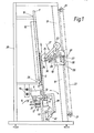
- Fig. 1 die wesentlichen Teile der Vorrichung in Seitenansicht, teilweise im Schnitt und
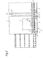
- Fig. 2 die Vorrichtung in Vorderansicht.
- Fig. 1 shows the essential parts of the device in side view, partly in section and
- Fig. 2 shows the device in front view.
Die Vorrichtung umfaßt eine im gezeigten Ausführingsbeispiel als Luftkissenwand ausgebildete, seitliche Stützwand 1 für die zu bearbeitenden, tafelförmigen E emente, wie beispielsweise metallisierte Glasscheiben 2. Unterhalb der Stützwand 1 ist eine Fördereinrichtung angeordnet. Vor (vgl. Fig. 2) und nach der Vorrichtug kann je ein An- und ein Abförderer angeordnet sein.The device comprises, in the exemplary embodiment shown, designed as an air cushion wall, lateral support wall 1 for the tabular elements to be processed, such as, for example,
Die Fördereinrichtung 3 umfaßt im gezeigten Ausfhrungs- beispiel zwei endlos umlaufende Förderbänder 4 t.d 5, die um Antriebs- bzw. Umlenkrollen 6 laufen und auf eichen die zu bearbeitenden Glasscheiben 2 aufstehen. Oerhalb der Förderbänder 4 und 5 sind vorzugsweise aus lastischem Werkstoff bestehende, frei drehbare Rollen 7 to gesehen, die im unteren horizontalen Randbereich der Gasscheibe 2 auf der Seite gegen deren Fläche anliegen, di an der Stützwand 1 gleitet.In the exemplary embodiment shown, the
Zwischen dem unteren Ende der Stützwand 1 und den Förderbändern 4 und 5 ist eine Mitnahmevorrichtung 8 vorgesehen. Diese Mitnahmevorrichtung 8 umfaßt einen Schlitten 9, der auf Führungsschienen 10 parallel zur Längserstreckung der Förderbänder 4 und 5 verschiebbar geführt ist. Der Schlitten 9 trägt wenigstens einen Saugkopf 11, welcher der auf der Stützwand 1 anliegenden Fläche einer Glasscheibe 2 zugekehrt ist.A
Zum Bewegen der Mitnahmevorrichtung 8 ist dieser ein Zahnriemen 12 zugeordnet, der mit der gleichen Lineargeschwindigkeit wie die Förderbänder 4 und 5 antreibbar ist. Dies kann beispielsweise dadurch erfolgen, daß der Zahnriemen 12 um Antriebsräder 12' läuft, die gleichachsig zu den Antriebsrädern 6 der Förderbänder 4 und 5 angeordnet sind. Soll nun die Mitnahmevorrichtung 8 synchron mit den Förderbändern 4 und 5 bewegt werden, dann wird diese vom Zahnriemen 12 angetrieben. Dies kann entweder dadurch erfolgen, daß durch eine Klemmvorrichtung 13 eine kraft-und/oder formschlüssige Verbindung zwischen Zahnriemen 12 und Schlitten 9 der Mitnahmevorrichtung 8 hergestellt wird, und/oder dadurch, daß der Schlitten 9 der Mitnahmevorrichtung 8 ständig mit dem Zahnriemen 12 gekuppelt ist und zwischen der Antriebswelle 31 und dem Antriebsrad 12' des Zahnriemens 12 eine lösbare Kupplung 32 vorgesehen ist.To move the
Jedenfalls ist durch diese Ausbildung des Antriebes für die Mitnahmevorrichtung 8 erreicht, daß diese auch bei in Betrieb gesetzten Förderbändern 4 und 5 stillstehen kann und bei ihrer Benützung jedenfalls synchron, d.h. mit gleicher Lineargeschwindigkeit wie die Förderbänder 4 und 5 bewegt wird.In any case, this design of the drive for the
Wie aus den Zeichnungen ersichtlich, ist in der Stützwand 1 ein Schlitz 14 vorgesehen, durch den eine Stützwalze 15 mit im wesentlichen vertikaler, zur Ebene der Stützwand 1 paralleler Achse 16 greift. Durch diese Stützwalze 15, an deren Stelle auch mehrere Stützrollen vorgesehen sein können und die, falls gewünscht, mit einer der Fördergeschwindigkeit der Förderbänder 4 und 5 entsprechenden Umfangsgeschwindigkeit angetrieben sein kann, wird eine Glasscheibe 2 im Bereich des Schlitzes 14 der Stützwand abgestützt.As can be seen from the drawings, a
Dem Schlitz 14 in der Stützwand 1 bzw. der in diesem angeordneten Stützwalze 15 gegenüberliegend, ist ein Bearbeitungswerkzeug 17 vorgesehen. Das Bearbeitungswerkzeug 17 ist über einen Schlitten 18 auf einer Führungsschiene 19, die sich parallel zur Stützwand 1 erstreckt, auf- und abverschiebbar. Die Führungsschiene 19 ist mit einem Rahmen 20 der Vorrichtung, an dem auch die Stützwand 1 und die Fördereinrichtung 3 sowie die Mitnahmevorrichtung 8 befestigt sind, starr verbunden. Zur Bewegung des Schlittens 18 und damit des Bearbeitungswerkzeuges 17 ist der Schlitten 18 mit einer über Umlenkrollen 21 laufenden Kette 22 verbunden, die durch einen nicht näher gezeigten Motor angetrieben wird.A processing tool 17 is provided opposite the
Am Schlitten 18 ist die beispielsweise als von einem Motor 23 antreibbare, als Bearbeitungswerkzeug dienende Scheibe 24 über eine Schwenkwelle 25, die ihrerseits in am Schlitten befestigten Lagerplatten 26 aufgenommen ist, getragen. An der Schwenkwelle 25 greift über einen mit ihr verbundenen Hebel 27 ein Druckmittelzylinder 28 an, so daß die Scheibe 24 aus der in Fig. 1 gezeigten Lage mit im wesentlichen horizontaler Drehachse, die zum Bearbeiten der lotrechten Randbereiche der Glasscheibe 1 bestimmt ist, um einen Winkel von 90° in eine Lage verschwenkt wird, in der die Drehachse der Scheibe 24 im wesentlichen vertikal ausgerichtet ist und die zum Bearbeiten der oberen und unteren horizontalen Randbereiche der Glasscheibe 2 dient.On the
Unterhalb der Walze 15 ist im Schlitz 14 dem Bearbeitungswerkzeug 17 gegenüberliegend, eine Lichtschranke 29, die beispielsweise als Reflexionslichtschranke ausgebildet sein kann, vorgesehen. Diese Lichtschranke 29 erfaßt die im wesentlichen vertikal ausgerichteten Ränder der Glasscheibe 2. Am Schlitten 28 ist eine weitere Lichtschranke 30 vorgesehen, mit welcher der obere horizontale Rand der Glasscheibe 2 erfaßt werden kann.Below the
Der Bewegungsweg des Schlittens 18 nach unten ist so begrenzt, daß in der unteren Endstellung das Bearbeitungswerkzeug 17 bzw. im gezeigten Ausführungsbeispiel die Bearbeitungsscheibe 24 in der für die Bearbeitung des unteren horizontalen Randes der Glasscheibe 2, dessen Höhenausrichtung ja durch die Förderbänder 4 und 5 bestimmt ist, richtigen Höhenlage ausgerichtet ist.The path of movement of the
Die soeben beschriebene Vorrichtung arbeitet wie folgt:
- In der Ausgangslage befindet sich der
Schlitten 18 mit dem Bearbeitungswerkzeug 17 in seiner unteren Endstellung und dieMitnahmevorrichtung 8 ist in einem demSchlitz 14 in der Stützwand 1 benachbarten Bereich, jedoch in Bewegungsrichtung gesehen, vor dem Schlitz liegend, angeordnet. Nun wird über den Zuführförderer eine zubearbeitende Glasscheibe 2 in die Vorrichtung gefördert, bis ihre vordere vertikale Kante durch dieLichtschranke 29 erfaßt wird, worauf dasFörderband 4 und 5 stillgesetzt wird. Die Glasscheibe nimmt dann eine Lage ein, in der ihre vordere vertikale Kante im Bearbeitungswerkzeug, das in seine Stellung mit horizontaler Drehachse derScheibe 24 verschwenkt ist, genau gegenüberliegt und von hinten durch dieWalze 15 abgestützt ist. Nun wird der Saugkopf 11 derMitnahmevorrichtung 8 aktiviert und dieMitnahmevorrichtung 8 mit dem Antrieb für dieFörderbänder 4 und 5 in der oben beschriebenen Weise gekuppelt.
- In the starting position, the
carriage 18 with the machining tool 17 is in its lower end position and theentraining device 8 is arranged in an area adjacent to theslot 14 in the support wall 1, but lying in front of the slot in the direction of movement. Now aglass pane 2 to be processed is conveyed into the device via the feed conveyor until its front vertical edge is detected by thelight barrier 29, whereupon theconveyor belts pane 24, and is supported by theroller 15 from behind. Now the suction head 11 of thedriving device 8 is activated and thedriving device 8 is coupled to the drive for theconveyor belts
Beispielsweise durch eine Folgesteuerung ausgelöst wird nun der Schlitten 18 und damit das Bearbeitungswerkzeug 17 solange nach oben bewegt, bis sich die Scheibe 24 in der vorderen oberen Ecke der Glasscheibe 2 befindet. Das Anhalten des Schlittens 18 in dieser Höhenlage wird durch die Lichtschranke 30 bewirkt. Nun verschwenkt das Bearbeitungswerkzeug 17 durch Betätigung des Druckmittelzylinders 28 um 90°, so daß die Achse der Scheibe 24 jetzt im wesentlichen vertikal ausgerichtet ist. Nun wird der Antrieb für die Förderbänder 4 und 5 und damit auch die Mitnahmevorrichtung 8 in Bewegung gesetzt und die Scheibe in Fig. 2 weiter nach rechts bewegt, während welcher Bewegung der obere horizontale Randbereich der Glasscheibe 2 bearbeitet wird. Sobald die zweite (hintere) vertikale Kante der Glasscheibe 2 die Lichtschranke 29 erreicht hat, wird die Glasscheibe 2 durch Stillsetzen der Antriebe für die Förderbänder 4 und 5 und die Mitnahmevorrichtung 8 angehalten, die Scheibe 24 durch Betätigung des Druckmittelzylinders 28 wieder in ihre Ausgangslage zurückgeschwenkt und der Schlitten 18 nach unten bewegt, wobei gleichzeitig der hintere Randbereich der Glasscheibe 2 bearbeitet wird. Sobald der Schlitten 18 seine untere Endlage erreicht hat, wird die Scheibe 24 wieder verschwenkt und hierauf die Antriebe für die Förderbänder 4 und 5 und die Mitnahmevorrichtung 8 derart in Bewegung gesetzt, daß die Scheibe in Fig. 2 nach links bewegt wird, während welcher Bewegung der untere horizontale Randbereich der Glasscheibe 2 bearbeitet wird.The
Nachdem dieser Randbereich fertig bearbeitet ist, wird der Vakuumsauger 11 von der Scheibe 2 gelöst und die Kupplung 31 des Antriebes für die Mitnahmevorrichtung 8 vom Antrieb für die Förderbänder 4 und 5 wieder gelöst. Hierauf können die Förderbänder 4 und 5 zum Abtransport der Glasscheibe 2 in Bewegung gesetzt werden.After this edge region has been finished, the vacuum suction device 11 is released from the
Die Stützwand 1 kann statt als Luftkissenwand auch als an sich bekannte Stützrollenwand ausgebildet sein.The support wall 1 can also be designed as a known support roller wall instead of an air cushion wall.
Anstelle der Polier- oder Schleifscheibe 24 kann das Bearbeitungswerkzeug auch einen Brenner mit einer oder mehreren Düsen umfassen, wobei die Düse(n) zur Glasscheibe hin gerichtet ist (sind).Instead of the polishing or grinding
Wie in Fig. 2 angedeutet, sind die im Bereich der Abstützwalze 15 vorgesehenen, frei drehbaren Rollen 7 breiter ausgebildet als die übrigen, frei drehbaren Rollen 7. Der Grund hiefür liegt darin, daß diesen Rollen 7 gegenüberliegend Führungsrollen 38 angeordnet sind, die an der zu bearbeitenden Fläche der Glasscheibe 2 anlegbar sind. Hiezu sind diese Führungsrollen 38 an einem Rahmen 39 montiert, der um eine Achse 40 durch einen Druckmittelzylinder 41 verschwenkbar im Gestell 20 der Vorrichtung gelagert ist. In der Regel werden am Rahmen zwei Führungsrollen 38 vorgesehen sein, die zu beiden Seiten des Bearbeitungswerkzeuges 17, wenn sich dieses in seiner unteren Ausgangsposition befindet, angeordnet sind. Beispielsweise besitzt der Rahmen 39 zwei Arme, die zu beiden Seiten der Bewegungsbahn des Bearbeitungswerkzeuges 17 angeordnet sind und die mit ihren oberen Enden die Förderbänder 4 und 5 übergreifend die Führungsrollen 38 tragen.As indicated in Fig. 2, the freely
Es versteht sich, daß zusätzlich zu dem auf- und abverschiebbaren Bearbeitungswerkzeug 17 beispielsweise zur Bearbeitung des unteren horizontalen Randes einer Glasscheibe im Bereich einer Unterbrechung der Fördereinrichtung 3 ein weiteres Randbearbeitungswerkzeug, das zur Be-arbeitung des unteren, horizontalen Randbereiches eines tafelförmigen Elementes 2 bestimmt ist, vorgesehen sein kann.It is understood that, in addition, for example, for processing the lower horizontal edge determines a glass pane in the region of an interruption of the
Die 'erfindungsgemß vorgesehene Mitnahmevorrichtung 8 kann mit dem tafelförmigen Element 2 auch schon verbunden werden, bevor dieses die durch die Lichtschranke 29 erfaßte Endstellung für die Bearbeitung des in Bewegungsrichtung vorderen, vertikalen Randbereiches erreicht hat. Hiezu kann im Bereich der Stützwand 1 eine weitere Lichtschranke 42 vorgesehen sein.The driving
Claims (16)
Applications Claiming Priority (2)
| Application Number | Priority Date | Filing Date | Title |
|---|---|---|---|
| AT1945/84 | 1984-06-14 | ||
| AT0194584A AT405724B (en) | 1984-06-14 | 1984-06-14 | DEVICE FOR MACHINING THE EDGE AREAS OF A GLASS PANEL |
Publications (4)
| Publication Number | Publication Date |
|---|---|
| EP0165232A2 true EP0165232A2 (en) | 1985-12-18 |
| EP0165232A3 EP0165232A3 (en) | 1987-09-30 |
| EP0165232B1 EP0165232B1 (en) | 1990-09-05 |
| EP0165232B2 EP0165232B2 (en) | 1996-12-27 |
Family
ID=3524429
Family Applications (1)
| Application Number | Title | Priority Date | Filing Date |
|---|---|---|---|
| EP85890129A Expired - Lifetime EP0165232B2 (en) | 1984-06-14 | 1985-06-13 | Apparatus for working the edges of flat elements |
Country Status (4)
| Country | Link |
|---|---|
| US (1) | US4716686A (en) |
| EP (1) | EP0165232B2 (en) |
| AT (1) | AT405724B (en) |
| DE (2) | DE8426496U1 (en) |
Cited By (6)
| Publication number | Priority date | Publication date | Assignee | Title |
|---|---|---|---|---|
| EP0709348A1 (en) | 1994-10-28 | 1996-05-01 | VIANELLO Fortunato - DAVANZO Nadia trading under the trading style FOR.EL. BASE DI VIANELLO & C. S.n.c. | Method and device for removing coatings deposited on the surface of a glass plate |
| EP0769348A1 (en) * | 1995-10-20 | 1997-04-23 | FOR.EL. BASE di VIANELLO FORTUNATO & C. S.n.c. | Method and device for removing coatings applied to the surface of a glass plate |
| DE19632240C2 (en) * | 1996-05-09 | 2001-10-04 | Hegla Fahrzeug Und Maschb Gmbh | Device and method for stripping flat glass raw plates |
| EP0920954A3 (en) * | 1997-12-02 | 2002-03-20 | Peter Lisec | Method and apparatus for bevelling pieces of cut glass |
| EP2123397A1 (en) * | 2006-12-04 | 2009-11-25 | Eckelt Glas GmbH | Device for processing fire-resistant glass |
| US11565363B2 (en) | 2016-10-14 | 2023-01-31 | Forel Spa | Automatic machine and automatic method for grinding the edges of glass sheets |
Families Citing this family (33)
| Publication number | Priority date | Publication date | Assignee | Title |
|---|---|---|---|---|
| AT405724B (en) * | 1984-06-14 | 1999-11-25 | Lisec Peter | DEVICE FOR MACHINING THE EDGE AREAS OF A GLASS PANEL |
| KR910001987Y1 (en) * | 1988-08-12 | 1991-03-30 | 박경 | Flat Glass Deformation Chamfering Machine |
| US5547063A (en) * | 1994-05-24 | 1996-08-20 | United Parcel Service Of America Inc. | Apparatus and method of sorting objects |
| AT402395B (en) * | 1995-10-13 | 1997-04-25 | Lisec Peter | DEVICE FOR REPLACING INSULATING GLASS PANELS |
| IT1288656B1 (en) * | 1996-09-13 | 1998-09-23 | For El Base Di Vianello Fortun | PROCEDURE FOR CUTTING GLASS SHEETS AND NON-REINFORCED LAMINATED GLASS SHEETS |
| IT1287347B1 (en) * | 1996-10-16 | 1998-08-04 | Castelmec Sas Di Rosso Valerio | DEVICE FOR THE EDGEBANDING OF GLASS SHEETS |
| IT1288675B1 (en) * | 1996-10-17 | 1998-09-23 | For El Base Di Vianello Fortun | AUTOMATIC PROCEDURE AND MACHINE FOR CUTTING LAMINATED AND ARMORED GLASS SHEETS |
| JP3915374B2 (en) * | 2000-06-27 | 2007-05-16 | 坂東機工株式会社 | Method and apparatus for removing coating layer on glass plate, and processing apparatus for glass plate provided with the device |
| JP2004518603A (en) | 2001-02-08 | 2004-06-24 | カーディナル・シージー・カンパニー | Edge treatment method for coated substrate |
| DE10158646A1 (en) * | 2001-11-22 | 2003-06-12 | Lenhardt Maschinenbau | Device for trimming glass panels |
| JP4254098B2 (en) * | 2001-12-06 | 2009-04-15 | 坂東機工株式会社 | Glass plate processing equipment |
| CA2464699C (en) * | 2002-12-05 | 2010-04-20 | Peter Lisec | Device for working of material plates, such as glass panes |
| US7125319B2 (en) | 2003-10-27 | 2006-10-24 | Corning Incorporated | Apparatus and method for grinding and/or polishing an edge of a glass sheet |
| US20050093207A1 (en) * | 2003-10-30 | 2005-05-05 | Simone John D. | Injection molding lid transfer apparatus and method |
| US7294045B1 (en) * | 2005-12-21 | 2007-11-13 | Corning Incorporated | Apparatus and method for edge processing of a glass sheet |
| CN101626969A (en) * | 2007-03-07 | 2010-01-13 | 株式会社爱发科 | Vacuum apparatus and substrate transfer method |
| US9309714B2 (en) | 2007-11-13 | 2016-04-12 | Guardian Ig, Llc | Rotating spacer applicator for window assembly |
| PL2220320T3 (en) | 2007-11-13 | 2020-01-31 | Guardian Glass, LLC | Sealed unit and spacer |
| US8449348B2 (en) * | 2009-01-13 | 2013-05-28 | Centre Luxembourg De Recherches Pour Le Verre Et La Ceramique S.A. (C.R.V.C.) | Techniques for debris reduction when performing edge deletion on coated articles having temporary protective coatings applied thereto |
| EP2580418B1 (en) | 2010-06-10 | 2014-08-13 | Guardian IG, LLC | Window spacer applicator |
| JP5677773B2 (en) * | 2010-07-09 | 2015-02-25 | 川崎重工業株式会社 | Plate member transfer equipment |
| IT1401927B1 (en) * | 2010-09-14 | 2013-08-28 | Neptun S R L | MILLING MACHINE WITH NUMERICAL CONTROL, PARTICULARLY FOR STRAIGHT-SIDED GLASS SHEETS. |
| US9656356B2 (en) * | 2013-01-22 | 2017-05-23 | Guardian Ig, Llc | Window unit assembly station and method |
| ITTV20130168A1 (en) | 2013-10-17 | 2015-04-18 | Forel Spa | AUTOMATIC MACHINE AND AUTOMATIC PROCEDURE FOR LOCALIZED REMOVAL OF COATINGS DEPOSITED ON GLASS SHEETS. |
| RU2612103C1 (en) | 2013-10-18 | 2017-03-02 | Лисец Аустриа Гмбх | Method for objects surface processing |
| AT516183B1 (en) * | 2014-10-06 | 2016-03-15 | Berndorf Band Gmbh | Method for grinding a weld of a metal strip |
| US11148228B2 (en) | 2017-07-10 | 2021-10-19 | Guardian Glass, LLC | Method of making insulated glass window units |
| US10987902B2 (en) | 2017-07-10 | 2021-04-27 | Guardian Glass, LLC | Techniques for laser ablation/scribing of coatings in pre- and post-laminated assemblies, and/or associated methods |
| US10472274B2 (en) | 2017-07-17 | 2019-11-12 | Guardian Europe S.A.R.L. | Coated article having ceramic paint modified surface(s), and/or associated methods |
| UA124077C2 (en) * | 2017-11-30 | 2021-07-14 | Лісец Аустріа Гмбх | Device for dividing material panels |
| IT202200006089A1 (en) * | 2022-03-29 | 2023-09-29 | Forel S P A Unipersonale | APPARATUS AND PROCEDURE FOR SLABS PROCESSING |
| IT202200017652A1 (en) * | 2022-08-25 | 2024-02-25 | Forel S P A Unipersonale | UNIT AND RELATED PROCEDURE FOR HOLDING A PLATE |
| DE102022123443A1 (en) | 2022-09-14 | 2023-08-31 | Glaston Germany GmbH | Process and device for manufacturing insulating glass panes |
Family Cites Families (35)
| Publication number | Priority date | Publication date | Assignee | Title |
|---|---|---|---|---|
| DE8335764U1 (en) * | 1984-07-05 | Lisec, Peter, Amstetten-Hausmening, Niederösterreich | Device for processing the edge areas of panel-shaped elements | |
| FR360126A (en) * | 1905-06-16 | 1906-04-13 | Joel Frankinet Kirby | Automatic beveling machine for all sizes of ice cream |
| US1831617A (en) * | 1928-07-26 | 1931-11-10 | Libbey Owens Ford Glass Co | Table for supporting glass sheets and method of bedding the same thereon |
| US1966869A (en) * | 1933-11-23 | 1934-07-17 | Pittsburgh Plate Glass Co | Apparatus for grinding the edges of glass sheets |
| US2075369A (en) * | 1935-09-30 | 1937-03-30 | Stetler Lowell | Marble refacing machine |
| US2671241A (en) * | 1947-08-23 | 1954-03-09 | Libbey Owens Ford Glass Co | Glass drying apparatus |
| US2551332A (en) * | 1947-11-06 | 1951-05-01 | Binswanger Mirror Co | Machine for processing sheetlike objects |
| GB743180A (en) * | 1951-06-12 | 1956-01-11 | Charles Edouard Chaudron | Improvements in or relating to the grinding and polishing of glass |
| IT501791A (en) * | 1953-05-26 | |||
| US2795086A (en) * | 1952-11-21 | 1957-06-11 | Libbey Owens Ford Glass Co | Edge finishing method and apparatus |
| GB851141A (en) * | 1957-12-16 | 1960-10-12 | Pilkington Brothers Ltd | Improvements relating to the production of bevels on glass plates |
| US3023548A (en) * | 1960-10-06 | 1962-03-06 | Sun Tool And Machine Company | Automatic contour edge grinder |
| US3565139A (en) * | 1968-08-06 | 1971-02-23 | Eugene T Olson | Angularly shiftable saw mount |
| GB1370945A (en) * | 1971-04-16 | 1974-10-16 | Triplex Safety Glass Co | Conveying apparatus |
| FR2195566A1 (en) * | 1972-08-07 | 1974-03-08 | Saint Gobain | Glass sheet edge machining holder - is rotatable and lockable in various settings |
| IT984759B (en) * | 1973-04-12 | 1974-11-20 | Zafferani A Nc Soc | AUTOMATIC MACHINE FOR THE MAKING OF DOUBLE GLASS INSULATING PANELS |
| US3835591A (en) * | 1973-05-14 | 1974-09-17 | Goodrich Co B F | Method and apparatus for correcting dimensional variation in a rotating tire |
| FR2237244A1 (en) * | 1973-07-12 | 1975-02-07 | Intercontinental Trading Cy | |
| US3918209A (en) * | 1974-08-19 | 1975-11-11 | British Oxygen Co Ltd | Metal removal apparatus |
| US3943667A (en) * | 1975-07-11 | 1976-03-16 | Acme Steel Door Corporation | Automatic weld grinding machine |
| BE838121R (en) * | 1976-01-30 | 1976-05-14 | GLASS PLATE EDGE CHAMFERING MACHINE | |
| US4060938A (en) * | 1976-04-20 | 1977-12-06 | Barron Sr Lee H | Glass beveling machine |
| US4354796A (en) * | 1976-05-10 | 1982-10-19 | Bergman Raymond A | Air float power translation system |
| JPS5493288A (en) * | 1977-12-31 | 1979-07-24 | Bando Kiko Co | Glass chamfering machine |
| US4228617A (en) * | 1977-12-31 | 1980-10-21 | Bando Kiko Co., Ltd | Method for grinding glass plates and the like through numerical control and beveling machine therefor |
| DE2846785C2 (en) * | 1978-10-27 | 1984-07-19 | Karl 7531 Neuhausen Lenhardt | Device for automatically filling the edge joints of double or multiple insulating glass panes with a sealant using filling nozzles |
| DE2816437B1 (en) * | 1978-04-15 | 1979-08-16 | Karl Lenhardt | Device for automatically filling the edge joints of insulating glass panes with a sealant by filling nozzles |
| GB1574751A (en) * | 1978-05-10 | 1980-09-10 | Wood Jenks & Co Ltd | Rectangular plate handling apparatus |
| DE2939571C2 (en) * | 1979-09-29 | 1982-08-12 | Paul Dipl.-Ing. 6925 Eschelbronn Ernst Jun. | Running conveyor belt for grinding machines |
| DE3205351A1 (en) * | 1982-02-15 | 1983-08-25 | Glas - und Spiegel-Manufactur AG, 4650 Gelsenkirchen | METHOD FOR PRODUCING INSULATED GLASS DISCS PROVIDED WITH A METALLIC REFLECTIVE SURFACE LAYER |
| EP0095228B1 (en) * | 1982-03-30 | 1986-06-11 | Pilkington Brothers P.L.C. | Treatment of coated glass |
| DE8318401U1 (en) * | 1983-06-24 | 1983-09-15 | Lisec, Peter, Amstetten-Hausmening, Niederösterreich | Device for conveying sheet-like elements |
| DE3448277C2 (en) * | 1984-03-09 | 1992-03-05 | Peter Amstetten-Hausmening At Lisec | |
| AT405724B (en) * | 1984-06-14 | 1999-11-25 | Lisec Peter | DEVICE FOR MACHINING THE EDGE AREAS OF A GLASS PANEL |
| JPH10446A (en) * | 1996-06-18 | 1998-01-06 | Kanegafuchi Chem Ind Co Ltd | Waste treatment agent and treatment method |
-
1984
- 1984-06-14 AT AT0194584A patent/AT405724B/en not_active IP Right Cessation
- 1984-09-07 DE DE19848426496U patent/DE8426496U1/en not_active Expired
-
1985
- 1985-06-13 EP EP85890129A patent/EP0165232B2/en not_active Expired - Lifetime
- 1985-06-13 DE DE8585890129T patent/DE3579505D1/en not_active Expired - Lifetime
- 1985-06-14 US US06/744,753 patent/US4716686A/en not_active Expired - Fee Related
Cited By (8)
| Publication number | Priority date | Publication date | Assignee | Title |
|---|---|---|---|---|
| EP0709348A1 (en) | 1994-10-28 | 1996-05-01 | VIANELLO Fortunato - DAVANZO Nadia trading under the trading style FOR.EL. BASE DI VIANELLO & C. S.n.c. | Method and device for removing coatings deposited on the surface of a glass plate |
| EP0769348A1 (en) * | 1995-10-20 | 1997-04-23 | FOR.EL. BASE di VIANELLO FORTUNATO & C. S.n.c. | Method and device for removing coatings applied to the surface of a glass plate |
| US5934982A (en) * | 1995-10-20 | 1999-08-10 | For.El. Base Di Vianello Fortunato & C. S.N.C. | Device for removing coatings applied to the surface of a glass plate |
| DE19632240C2 (en) * | 1996-05-09 | 2001-10-04 | Hegla Fahrzeug Und Maschb Gmbh | Device and method for stripping flat glass raw plates |
| EP0920954A3 (en) * | 1997-12-02 | 2002-03-20 | Peter Lisec | Method and apparatus for bevelling pieces of cut glass |
| EP1344604A3 (en) * | 1997-12-02 | 2003-09-24 | Tecnopat AG | Method and apparatus for bevelling pieces of cut glass |
| EP2123397A1 (en) * | 2006-12-04 | 2009-11-25 | Eckelt Glas GmbH | Device for processing fire-resistant glass |
| US11565363B2 (en) | 2016-10-14 | 2023-01-31 | Forel Spa | Automatic machine and automatic method for grinding the edges of glass sheets |
Also Published As
| Publication number | Publication date |
|---|---|
| EP0165232B1 (en) | 1990-09-05 |
| EP0165232B2 (en) | 1996-12-27 |
| US4716686A (en) | 1988-01-05 |
| AT405724B (en) | 1999-11-25 |
| ATA194584A (en) | 1989-04-15 |
| DE8426496U1 (en) | 1984-11-29 |
| DE3579505D1 (en) | 1990-10-11 |
| EP0165232A3 (en) | 1987-09-30 |
Similar Documents
| Publication | Publication Date | Title |
|---|---|---|
| EP0165232B1 (en) | Apparatus for working the edges of flat elements | |
| DE3637561C2 (en) | ||
| DE50208224C5 (en) | DEVICE AND METHOD FOR MOVING GLASS PANELS WHILE MACHINING THEM | |
| DE2623327A1 (en) | EQUIPMENT FOR THE TRANSPORTATION AND GUIDING OF GOODS | |
| DE29819320U1 (en) | Device for hemming glass blanks | |
| EP1314513B1 (en) | Apparatus for trimming of glass plates | |
| DE2756443A1 (en) | GLASS TRIM MACHINE WITH ROLLER TRACK | |
| DE2919875B1 (en) | System for automatic grinding of the edges of glass panes | |
| DE2430043A1 (en) | Cutting out for paper stacks or book pads - individual stacks clamped on continually moving supports prior to cutting | |
| DE2122990C3 (en) | Machine for processing the edges of glass panes or the like. | |
| DE1421789B2 (en) | Device for preventing damage to glass plates during their removal from the table of the glass cutting machine | |
| DE3830856C1 (en) | ||
| DE1900228A1 (en) | Device for continuous end-face profiling and glue application of wood to be joined together at the end | |
| EP0362833A2 (en) | Wood-working machine, in particular a moulder | |
| DE2752648A1 (en) | Circular cutter attached to cross slide - produces tapered lead=in edge on moving strip material | |
| DE3408675A1 (en) | Apparatus for machining the edge regions of elements in the form of panes | |
| DE649758C (en) | Sheet delivery device on corner conveyor tables of folding machines | |
| DE1226754B (en) | Device for breaking strips from a moving pane of glass | |
| AT403911B (en) | Method and apparatus for removal of a metal coating from glass plates | |
| DE4006662C2 (en) | ||
| EP0060501B1 (en) | Arc-machining tool | |
| DE1561509C (en) | Device for applying an adhesive strip to sheets | |
| DE2112908A1 (en) | Glass cutting machine - esp for cutting a sheet - into small rectangular pieces | |
| DE1921554B2 (en) | Machine cutting mitre grooves in panels - uses continuous conveyor guide track and reinforcing layer cutter | |
| DE69407517T2 (en) | Automatic device for producing round bluntings at corners of plates |
Legal Events
| Date | Code | Title | Description |
|---|---|---|---|
| PUAI | Public reference made under article 153(3) epc to a published international application that has entered the european phase |
Free format text: ORIGINAL CODE: 0009012 |
|
| AK | Designated contracting states |
Designated state(s): DE FR GB IT |
|
| PUAL | Search report despatched |
Free format text: ORIGINAL CODE: 0009013 |
|
| AK | Designated contracting states |
Kind code of ref document: A3 Designated state(s): DE FR GB IT |
|
| 17P | Request for examination filed |
Effective date: 19880329 |
|
| 17Q | First examination report despatched |
Effective date: 19890720 |
|
| ITF | It: translation for a ep patent filed | ||
| GRAA | (expected) grant |
Free format text: ORIGINAL CODE: 0009210 |
|
| AK | Designated contracting states |
Kind code of ref document: B1 Designated state(s): DE FR GB IT |
|
| ET | Fr: translation filed | ||
| GBT | Gb: translation of ep patent filed (gb section 77(6)(a)/1977) | ||
| REF | Corresponds to: |
Ref document number: 3579505 Country of ref document: DE Date of ref document: 19901011 |
|
| PLBI | Opposition filed |
Free format text: ORIGINAL CODE: 0009260 |
|
| 26 | Opposition filed |
Opponent name: LENHARDT MASCHINENBAU GMBH Effective date: 19901013 |
|
| ITTA | It: last paid annual fee | ||
| APAC | Appeal dossier modified |
Free format text: ORIGINAL CODE: EPIDOS NOAPO |
|
| PLAW | Interlocutory decision in opposition |
Free format text: ORIGINAL CODE: EPIDOS IDOP |
|
| PUAH | Patent maintained in amended form |
Free format text: ORIGINAL CODE: 0009272 |
|
| STAA | Information on the status of an ep patent application or granted ep patent |
Free format text: STATUS: PATENT MAINTAINED AS AMENDED |
|
| 27A | Patent maintained in amended form |
Effective date: 19961227 |
|
| AK | Designated contracting states |
Kind code of ref document: B2 Designated state(s): DE FR GB IT |
|
| ITF | It: translation for a ep patent filed | ||
| GBTA | Gb: translation of amended ep patent filed (gb section 77(6)(b)/1977) |
Effective date: 19891224 |
|
| ET3 | Fr: translation filed ** decision concerning opposition | ||
| REG | Reference to a national code |
Ref country code: GB Ref legal event code: IF02 |
|
| PGFP | Annual fee paid to national office [announced via postgrant information from national office to epo] |
Ref country code: GB Payment date: 20040609 Year of fee payment: 20 |
|
| PGFP | Annual fee paid to national office [announced via postgrant information from national office to epo] |
Ref country code: FR Payment date: 20040610 Year of fee payment: 20 |
|
| PGFP | Annual fee paid to national office [announced via postgrant information from national office to epo] |
Ref country code: DE Payment date: 20040819 Year of fee payment: 20 |
|
| PG25 | Lapsed in a contracting state [announced via postgrant information from national office to epo] |
Ref country code: GB Free format text: LAPSE BECAUSE OF EXPIRATION OF PROTECTION Effective date: 20050612 |
|
| REG | Reference to a national code |
Ref country code: GB Ref legal event code: PE20 |
|
| APAH | Appeal reference modified |
Free format text: ORIGINAL CODE: EPIDOSCREFNO |