EP0709348A1 - Method and device for removing coatings deposited on the surface of a glass plate - Google Patents
Method and device for removing coatings deposited on the surface of a glass plate Download PDFInfo
- Publication number
- EP0709348A1 EP0709348A1 EP95116238A EP95116238A EP0709348A1 EP 0709348 A1 EP0709348 A1 EP 0709348A1 EP 95116238 A EP95116238 A EP 95116238A EP 95116238 A EP95116238 A EP 95116238A EP 0709348 A1 EP0709348 A1 EP 0709348A1
- Authority
- EP
- European Patent Office
- Prior art keywords
- glass plate
- head
- electrodes
- layers
- coating
- Prior art date
- Legal status (The legal status is an assumption and is not a legal conclusion. Google has not performed a legal analysis and makes no representation as to the accuracy of the status listed.)
- Granted
Links
Images


Classifications
-
- C—CHEMISTRY; METALLURGY
- C03—GLASS; MINERAL OR SLAG WOOL
- C03C—CHEMICAL COMPOSITION OF GLASSES, GLAZES OR VITREOUS ENAMELS; SURFACE TREATMENT OF GLASS; SURFACE TREATMENT OF FIBRES OR FILAMENTS MADE FROM GLASS, MINERALS OR SLAGS; JOINING GLASS TO GLASS OR OTHER MATERIALS
- C03C23/00—Other surface treatment of glass not in the form of fibres or filaments
-
- C—CHEMISTRY; METALLURGY
- C03—GLASS; MINERAL OR SLAG WOOL
- C03C—CHEMICAL COMPOSITION OF GLASSES, GLAZES OR VITREOUS ENAMELS; SURFACE TREATMENT OF GLASS; SURFACE TREATMENT OF FIBRES OR FILAMENTS MADE FROM GLASS, MINERALS OR SLAGS; JOINING GLASS TO GLASS OR OTHER MATERIALS
- C03C17/00—Surface treatment of glass, not in the form of fibres or filaments, by coating
-
- E—FIXED CONSTRUCTIONS
- E06—DOORS, WINDOWS, SHUTTERS, OR ROLLER BLINDS IN GENERAL; LADDERS
- E06B—FIXED OR MOVABLE CLOSURES FOR OPENINGS IN BUILDINGS, VEHICLES, FENCES OR LIKE ENCLOSURES IN GENERAL, e.g. DOORS, WINDOWS, BLINDS, GATES
- E06B3/00—Window sashes, door leaves, or like elements for closing wall or like openings; Layout of fixed or moving closures, e.g. windows in wall or like openings; Features of rigidly-mounted outer frames relating to the mounting of wing frames
- E06B3/66—Units comprising two or more parallel glass or like panes permanently secured together
- E06B3/673—Assembling the units
-
- C—CHEMISTRY; METALLURGY
- C03—GLASS; MINERAL OR SLAG WOOL
- C03C—CHEMICAL COMPOSITION OF GLASSES, GLAZES OR VITREOUS ENAMELS; SURFACE TREATMENT OF GLASS; SURFACE TREATMENT OF FIBRES OR FILAMENTS MADE FROM GLASS, MINERALS OR SLAGS; JOINING GLASS TO GLASS OR OTHER MATERIALS
- C03C2218/00—Methods for coating glass
- C03C2218/30—Aspects of methods for coating glass not covered above
- C03C2218/32—After-treatment
- C03C2218/328—Partly or completely removing a coating
Abstract
Description
- The present invention relates to a method and a device for removing coatings that are deposited on the surface of a glass plate and are constituted by one or more layers that include at least one conducting layer.
- Nowadays it is known to perform a treatment known as "low emissivity" during the manufacture of special glass plates; substantially, this treatment has the purpose of constituting a barrier to the passage of infrared rays and thus limiting the outward transmission of heat from indoor spaces.
- This treatment consists in applying a plurality of layers of material on the entire surface of a glass plate, which must then be perimetrically associated, by means of a first butyl seal, at the lateral surfaces of a spacer frame so as to form the inner space of an insulating glazing unit.
- A typical succession of layers, starting from the surface of the glass plate, for the so-called magnetron quality, is as follows: a first layer of non-conducting tin oxide that is strongly bonded to the glass, for a thickness of approximately 300 angstrom.
- A second layer of conducting silver approximately 100 angstrom thick and a third layer of equally conducting aluminum approximately 35 angstrom thick are deposited or applied on the first layer.
- A fourth layer of non-conducting tin oxide approximately 300 angstrom thick, with substantially protective features, is also provided.
- The glass plates thus treated must be conveniently protected starting from packaging up to processing, until the time when they form the double-glazing unit and when they are no longer exposed to the aggression of atmospheric agents, since their treated surface is directed towards the inner space of the unit.
- These layers, however, can become inalterable only if the continuity of the coating is interrupted towards the outer edge of the glass plate; this continuity, even if being atomic in thickness, would in fact be sufficient to trigger oxidation of the outer edge of the glass plate towards the inside of the insulating glazing unit, consequently compromising characteristics that are indispensable for a good quality of the insulating glazing unit, such as the bonding of the sealant that constitutes the second seal, the bonding of the sealant that constitutes the first seal, the effectiveness of the "low emissivity" coating, as well as their aesthetics.
- Accordingly, it is known to fully remove the layers proximate to the edge of the glass plates.
- It is therefore known to perform removal by using heat as an agent for removing the layers: it is accordingly known to use a combustible gas torch, whose flame is passed at said edge of the glass plate.
- However, this solution has currently been abandoned, since insufficient quality of the result and objective difficulty in automating the method have been observed.
- In the field, it is known also to totally remove the layers at the edge of the glass plate by grinding.
- The support for the abrasive mix is usually constituted by a low-hardness rubber-like material, so that the action against the surface of the glass plate is as tolerable as possible.
- This conventional method substantially consists in running along the perimeter of the glass plate with a grinder, generally of the peripheral type, the glass plate being placed on a horizontal surface, with the part to be treated facing up.
- This conventional manual method has considerable drawbacks, since there is no control at all of the pressure of the grinder against the surface of the glass plate except for the control based on the mere sensitivity of the operator.
- Furthermore, the produced dust contains abrasive particles and in any case other foreign particles constituted by the mix material, and constitutes a dangerous contaminant for the glass plate and particularly for its treated surface, which is highly sensitive, especially in the grinding treatment known as "edging" and in the subsequent treatments, which range from washing to the coupling of two or more glass plates to form the insulating glazing units.
- It is also known to perform the removal by grinding with a semiautomatic method that differs from the preceding one in that the operation always occurs on a horizontal table where however, the feeding motion, in addition to the cutting motion is motorized.
- However, manual work still occurs in the operations for centering the glass plate and for starting and stopping the grinders one side at a time.
- In both these procedures, the effectiveness of dust aspiration is uncertain both due to the limited power installed on these machines and due to the horizontal position of the glass plate; considerable problems of contamination of the surface of the glass plate remain in any case.
- It is then known to perform removal by grinding in an automatic manner: this removal occurs on a glass plate that is slightly arranged inclined with respect to the vertical plane, and in addition to being performed fully automatically around the entire perimeter of the glass plate, either by the simple feeding motion of the grinder or by combining the feeding motion of the grinder and of the glass plate, it also introduces an attempt to control the pressure of the grinder against the surface of the glass plate.
- However, this control is not easy to be carried out, due to the size of the glass plate, since it is necessary to work at its rim and therefore in a borderline situation, due to the variability of the features of the grinder, since the diameter of the grinder varies according to wear and since the glass plate can be scratched in view of the limited thickness of the applied layers.
- An example of the mentioned method is provided by European patent no. EP 0165232, whose solution, however, has all the above-mentioned drawbacks.
- All conventional removal methods suffer the drawbacks of removing all the deposited layers and even of contaminating the surface of the glass plate, which thus becomes rough and changes its composition; these characteristics are not adapted for the correct bonding of the first seal, constituted by butyl sealant, and of the second seal, which is performed with polysulfide or polyurethane or silicone sealants.
- The aim of the present invention is therefore to solve the described technical problems, eliminating the drawbacks of the prior art, by providing a method and a device that allow to manually and automatically treat the edge of glass plates on which coatings, constituted by one or more layers including at least one conducting layer, are applied, and at the same time allow optimum bonding of the first and second seals to form the insulating glazing unit.
- Within the scope of the above aim, an object is to achieve selective or controlled removal of the coating, optionally leaving a substrate bonded to the surface of the glass plate that has optimum adhesion characteristics for the sealants constituting the first seal and the second seal.
- Within the scope of the above aim, another important object is to provide a method and a device that in no way contaminate the surface of the glass plate.
- Another important object is to provide a method and a device that, as a consequence of the treatment of the edge of the glass plate, also allow to prevent oxidation of the layers and thus maintain all the physical and aesthetic characteristics of the treated glass plate.
- Another object is to provide a device that allows a precise and preset delimitation of the treated surface of the glass plate.
- Another object is to provide a device according to the invention that is reliable and safe in use.
- This aim, these objects, and others which will become apparent hereinafter are achieved by a method for removing coatings, constituted by a plurality of layers including at least one conducting layer, that are applied to the surface of a glass plate, characterized in that it comprises: a first step for moving said glass plate to the vicinity of one or more electrodes; a second step for moving or positioning said one or more electrodes proximate to the edge of said glass plate; a third step, in which a current is circulated in said one or more electrodes; and a fourth step, in which said glass plate or said one or more electrodes are moved along said edge to selectively remove one or more of said layers; and by a device for removing coatings, constituted by a plurality of layers that include at least one conducting layer and are deposited on the surface of a glass plate; characterized in that it is constituted by at least one head that can move along the edge of said glass plates and has at least one electrode that is adapted to cause the circulation of electric current and/or an electrical discharge on said surface for the selective removal of one or more of said layers.
- Further characteristics and advantages of the invention will become apparent from the following detailed description of some particular but not exclusive embodiments, illustrated only by way of non-limitative example in the accompanying drawings, wherein:
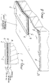
- figure 1 is a front view of a rack and of a roller conveyor for conveying the glass plate, and of the device applied at horizontal and vertical carriages;
- figure 2 is a side view of the elements of figure 1;
- figure 3 is a top view of the elements of figure 1;
- figure 4 is an enlarged-scale transverse sectional view of the application of a number of layers on the surface of a glass plate;
- figures 5 and 6 are schematic top views of the use of the device in two possible embodiments;
- figure 7 is a schematic view of the device;
- figure 8 is an enlarged-scale, partially sectional, lateral perspective view of an example of selective layer removal;
- figure 9 is a view, similar to figure 7, of a further embodiment of the device.
- With reference to the above figures, the
reference numeral 1 designates a glass plate that can be coupled to a similar glass plate by means of a first seal at a spacer frame, so as to constitute an inner space of an insulating glazing unit. - The spacer can be constituted by a closed profile that is internally hollow and has adapted fine holes on the surface located at the inner space and adapted hygroscopic materials inside.
-
Said glass plate 1 has acoating 3 applied thereto at thesurface 2 that is to be in contact with the inner space of the insulating glazing unit (if total removal is performed); said coating is constituted by a plurality of layers of material for example of the type used for the so-called "low-emissivity' treatment or in any case for other treatments such as, in a non-limitative sense, those for producing a tinted or reflective or photochromic glass plate. - In the described solution, which is illustrated only by way of example, a first
non-conducting layer 4 of tin oxides, over which a second conductinglayer 5 of silver and a subsequentthird layer 6 of aluminum are applied, have been considered. - There is also a fourth
non-conducting layer 7 of tin oxide that has substantially protective features. - The
glass plate 1 can be conveyed by means of an adaptedroller conveyor 8 for lower support and of avertical rack 9 for rear support; said roller conveyor and said rack allow to convey the glass plate to the coating removal device. - Said device is constituted by a first fixed
head 10 and by a second movable head 11: thefirst head 10 acts at thelower edge 12 of theglass plate 1, whereas the second head 11 is associated with an adapted actuation means comprising amotorized belt 13 and is allowed to perform a sustantially vertical motion; both of said heads can rotate through 90o with respect to said belt. - There is also a
first carriage 14 for feeding the glass plate in a horizontal direction; by means of appropriate suckers, said carriage engages the glass plate on the surface that lies opposite to thesurface 2 and carries it toward the coating removal device. - There is also a
second carriage 15 for the vertical movement of the second head 11. - Each one of said first and second heads has, in the particular illustrated solution,
electrodes 16 that are supplied by adapted power sources and are adapted to cause the circulation of electric current and/or an electrical discharge at the surface of thecoating 3 to achieve selective removal of one or more of the underlying layers. - The method in fact entails a first step, in which the glass plate is loaded onto the
rack 9 and then carried up to a reference position for the first and second heads; a second step entails placing or moving said electrodes at thecoating 3 proximate to theedge 12. - This is followed by a third step, in which the electrodes are supplied with power, and by a fourth step, in which the second head 11 performs a vertical upward stroke, selectively removing some layers of the
coating 3 and in particular thefourth layer 7, thethird layer 6, and thesecond layer 5. - An adapted sensor stops the second hed 11 at the upper horizontal edge of the glass plate and simultaneously the second head 11 rotates through 90o, placing the electrodes at the
edge 12 of the upper side of the glass plate. - At the same time, the
first head 10 places the electrodes at theedge 12 of the lower side of theglass plate 1; then theroller conveyor 8 is actuated, causing the movement of the glass plate and consequently allowing to selectively remove the second, third, and fourth layers of thecoating 3 until the end of the glass plate is reached. - At this point, the
first head 10 moves the electrodes away from the glass plate and the second head 11 performs an additional 90o rotation and then moves downward and selectively removes the second, third, and fourth layers until, when it reaches the lower end of the glass plate, said glass plate is moved away or the electrodes are moved away therefrom. - The
second head 10 is then replaced for the subsequent treatment of another glass plate. - Said first and second heads also have electric and/or electronic means that are adapted to produce the circulation of current and/or the discharge at the electrodes; if said means are of the electronic type, they can be constituted by appropriate circuits, schematically designated by the
reference numeral 17, or can be constituted for example by atransformer 18, in which theprimary winding 19 is associated with a power source and thesecondary winding 20 is connected to theelectrodes 16. - Selective removal of the second, third, and fourth layers occurs by means of the
second layer 5 and of thethird layer 6 which, by conducting, allow to close the circuit of theelectrodes 16. - The fact that the
fourth layer 7 is made of nonconducting material is not a problem; since it is a film at the atomic level, the discharge of the electrodes perforates it and closes on the internal layers constituted by metals that sublimate when the current flows. - Said current flow or the discharge of the electrodes does not affect the
first layer 4, since it is nonconducting and since below said first layer there is only the glass plate, which is nonconducting too. - As regards the type and shape of the electrodes, they may be of the cylindrical type, as shown in figures 5, 7, and 9, or they may have a different shape; in figure 6, one of said electrodes has a cylindrical shape and the other one has a laminar shape.
- The present invention is of course susceptible of numerous modifications and variations, all of which are within the scope of the same inventive concept.
- Therefore, the type of the layers that constitute the coating might be any, so long as it contains electrically conducting layers, and likewise the combination of said layers might be any.
- As an alternative, an electrode that allows to achieve selective removal by virtue of the emission of a laser beam can be associated with each one of the heads, whose number can be variable.
- The device also comprises adapted electronically-controlled actuators for controlling the movement of the glass plate and/or of the heads that support the electrodes; said actuators handle, in a controlled manner, the conditions of the acceleration and deceleration gradients of said glass plate and/or said heads.
- The device also comprises one or more aspirator hoods that are adapted to remove the gaseous products emitted during selective removal of the layer of the coating.
- Conveniently, the electrodes can also be complemented by an adapted filler gas with protective or reactive functions.
- The method can of course occur in a fully automatic or semi-automatic or manual manner.
- Finally, it is noted that the selective or controlled removal of one or more layers of the coating of the glass plate can occur while said glass plate is arranged substantially vertically or on a horizontal or inclined plane.
- The materials and the dimensions that constitute the individual components of the invention as well as the sequence of the steps of the method may of course also be the most pertinent according to the specific requirements.
- Where technical features mentioned in any claim are followed by reference signs, those reference signs have been included for the sole purpose of increasing the intelligibility of the claims and accordingly such reference signs do not have any limiting effect on the interpretation of each element identified by way of example by such reference signs.
Claims (21)
- Device for removing coatings (3) comprising a plurality of layers (4-7) that include at least one conducting layer (5,6) and are deposited on the surface (2) of a glass plate (1), characterized in that it comprises at least one head (10,11) that can move along the edge (12) of said glass plates (1), said at least one head having at least one electrode (16) that is adapted to cause the circulation of electric current and/or an electrical discharge on said surface (2) to selectively remove one or more of said layers (4-7).
- Device according to claim 1, usable on a glass plate (1) coupleable to a similar or ordinary further simple glass plate, through a first seal, at a spacer frame so as to constitute the inner space of an insulating glazing unit; and wherein the spacer frame comprises a closed profile that is internally hollow, said profile having adapted fine holes on the surface located at the inner space, and containing inside hygroscopic materials, said glass plate (1) having, at the surface (2) that lies in contact with said inner space, a coating (3) that comprises a plurality of layers (4-7) of material of the type used for the so-called "low emissivity" treatment or for other treatments, such as those for producing a tinted or reflecting or photochromic glass plate; said device further comprising: an adapted roller conveyor (8) for lower and a rack (9) for rear support and transport of said glass plate (1), to said at least one head, said heads comprising a first fixed head (10) and a second movable head (11).
- Device according to claims 1 and 2, characterized in that said first head (10) acts at the lower edge (12) of said glass plate (1).
- Device according to claims 1 and 2, characterized in that said second head (11) is movably associated with an adapted motorized belt (13) for moving substantially vertically and to rotate through 90o and 180o with respect to an axis of said belt (13).
- Device according to claims 1, 3, and 4, characterized in that it further comprises a first carriage (14) for feeding said glass plate (1) in a horizontal direction, said first carriage (14) having suckers for engaging said glass plate (1) on the side that lies opposite to the one on which said coating (3) is applied and for conveying said glass plate toward said coating removal heads (10,11); a second carriage (15) for the vertical movement of said second head (11), each one of said first (10) and second (11) heads having a plurality of electrodes (16) that are supplied by appropriate sources and are adapted to cause the circulation of electric current and/or an electrical discharge at the surface of said coating (3) to selectively remove one or more of said underlying layers (4-7).
- Device according to claims 1 and 5, characterized in that said first and second heads (10,11) have electric and/or electronic means (17,18) that are adapted to cause the circulation of current and/or the discharge at said one or more electrodes (16).
- Device according to claims 1 and 6, characterized in that said means are of the electric type and are constituted by a transformer (18), in which the primary winding 19 is associated with a power source and the secondary winding (20) is connected to two electrodes (16).
- Device according to claims 1, 6, and 7, characterized in that said one or more electrodes (16) have any adapted shape, such as a cylindrical and/or laminar one.
- Device according to one or more of the preceding claims, characterized in that it comprises at least one head (10,11) which emits a laser beam for controlled removal of said coating constituted by a plurality of layers (4-7), said coating including possibly no conducting layers.
- Method for removing coatings constituted by a plurality of layers (4-7) that include at least one conducting layer (5,6) and are applied to the surface (2) of a glass plate (1), characterized in that it comprises: a first step for moving said glass plate (1) to the vicinity of one or more electrodes (16); a second step for moving or positioning said one or more electrodes (16) proximate to the edge (12) of said glass plate (1); a third step, in which a current is circulated in said one or more electrodes (16); and a fourth step, in which said glass plate (1) or said plurality of electrodes (16) are moved along said edge to selectively remove one or more of said layers.
- Method according to claim 10, characterized in that in said first step said glass plate is loaded on a rack and is carried to a reference position for a first head and a second head.
- Method according to claim 10, characterized in that in said second step said electrodes (16) are moved or positioned at said coating (3) proximate to the edge (12) of said glass plate (1).
- Method according to any of claims 10, 11 and 12, characterized in that said plurality of electrodes (16) are supplied with power in said third step, and in that in a fourth optionally simultaneous step said second head (11) performs an upward vertical stroke, selectively removing one or more of said layers (4-7) of said coating (3).
- Method according to any of the claims 10-13, characterized in that an adapted sensor stops said second head (11) at the upper horizontal edge of said glass plate (1) and simultaneously said second head (11) performs a 90o rotation, arranging the electrodes (16) at the edge (12) of the upper side of said glass plate (1), said first head (10) simultaneously placing said one or more electrodes (16) at the edge (12) of the lower side of said glass plate (1), this being followed by the actuation of a roller conveyor (8) that is adapted to move said glass plate (1), and then by the selective removal of one or more of said layers (4-7) of said coating (3).
- Method according to any of the claims 10-14, characterized in that said first head (10) moves further said one or more electrodes (16) away from said glass plate (1) and said second head (11) performs a further rotation through 90o and then moves downward and selectively removes said coating (3) until it reaches the lower end of said glass plate (1) and is then moved away from it.
- Method according to any of the claims 10-15, characterized in that said glass plate (1) has straight or curved contours.
- Method according to one or more of claims 10-16, characterized in that the movements of said glass plate (1) and/or of said at least one head (10,11) provided with said one or more electrodes (16) are performed by means of actuators that are controlled electronically and are adapted to handle, in a controlled manner, the conditions of acceleration and deceleration gradients of said glass plate (1) or of said at least one head (10,11).
- Device for carrying out the method of claims 10-17, characterized in that it further comprises one ore more aspirator hoods that are adapted to remove the gaseous products released during the selective or controlled removal of said one or more layers of said coating.
- Method according to one or more of claims 10-17, characterized in that said treatment electrodes (16) are complemented by an adapted filler gas with protective or reactive functions.
- Method according to one or more of claims 10-17 and 19, characterized in that said selective or controlled removal is performed on said glass plate (1) while it is arranged on a substantially vertical or horizontal or inclined plane.
- Method according to one or more of claims 10-17 and 19-21, characterized in that said selective controlled removal of said one or more layers (4-7) occurs in a fully automatic or semiautomatic or manual manner.
Applications Claiming Priority (2)
| Application Number | Priority Date | Filing Date | Title |
|---|---|---|---|
| ITTV940126 | 1994-10-28 | ||
| ITTV940126A IT1273917B (en) | 1994-10-28 | 1994-10-28 | PROCEDURE AND DEVICE FOR THE REMOVAL OF COATINGS DEPOSITED ON THE SURFACE OF A GLASS. |
Publications (2)
| Publication Number | Publication Date |
|---|---|
| EP0709348A1 true EP0709348A1 (en) | 1996-05-01 |
| EP0709348B1 EP0709348B1 (en) | 1999-01-20 |
Family
ID=11419538
Family Applications (1)
| Application Number | Title | Priority Date | Filing Date |
|---|---|---|---|
| EP95116238A Expired - Lifetime EP0709348B1 (en) | 1994-10-28 | 1995-10-16 | Method and device for removing coatings deposited on the surface of a glass plate |
Country Status (6)
| Country | Link |
|---|---|
| EP (1) | EP0709348B1 (en) |
| JP (1) | JPH08208277A (en) |
| KR (1) | KR960014043A (en) |
| AT (1) | ATE175952T1 (en) |
| DE (1) | DE69507422T2 (en) |
| IT (1) | IT1273917B (en) |
Cited By (6)
| Publication number | Priority date | Publication date | Assignee | Title |
|---|---|---|---|---|
| EP1167312A1 (en) * | 2000-06-27 | 2002-01-02 | Bando Kiko Co. Ltd. | Method of and appliance for removing a film layer on a glass plate and glass-plate working unit comprising a station equipped with this appliance |
| WO2002062715A1 (en) * | 2001-02-08 | 2002-08-15 | Cardinal Cg Company | Method and apparatus for removing coatings applied to surfaces of a substrate |
| WO2004114357A1 (en) * | 2003-06-16 | 2004-12-29 | Saint-Gobain Glass France | Method and device for removing layers in some areas of glass plates |
| US7682220B2 (en) | 2001-12-06 | 2010-03-23 | Bando Kiko Co., Ltd. | Glass-plate working apparatus |
| US8038892B2 (en) * | 2004-11-19 | 2011-10-18 | Vetrotech Saint-Gobain (International) Ag | Method and device for strip and flat-shaping machining surfaces of glass panes |
| WO2021083755A1 (en) | 2019-10-31 | 2021-05-06 | Saint-Gobain Glass France | Laminated pane having a heat-radiation reflecting coating |
Citations (5)
| Publication number | Priority date | Publication date | Assignee | Title |
|---|---|---|---|---|
| GB803371A (en) * | 1955-09-07 | 1958-10-22 | Libbey Owens Ford Glass Co | Method of removing an electrically conducting film |
| EP0165232A2 (en) | 1984-06-14 | 1985-12-18 | Peter Lisec | Apparatus for working the edges of flat elements |
| DE4006502A1 (en) * | 1990-03-02 | 1990-10-25 | Ruediger Meyer | Lacquer-coated metal film removal from mirror - using heated copper electrode |
| EP0412812A1 (en) * | 1989-08-10 | 1991-02-13 | Solaglas Limited | Method of changing the appearance of glass |
| WO1993025487A1 (en) * | 1992-06-15 | 1993-12-23 | Aulis Bertin | Method for the pre-treatment of coated glasses before heat treatment |
-
1994
- 1994-10-28 IT ITTV940126A patent/IT1273917B/en active IP Right Grant
-
1995
- 1995-10-16 AT AT95116238T patent/ATE175952T1/en not_active IP Right Cessation
- 1995-10-16 EP EP95116238A patent/EP0709348B1/en not_active Expired - Lifetime
- 1995-10-16 DE DE69507422T patent/DE69507422T2/en not_active Expired - Fee Related
- 1995-10-27 KR KR1019950037587A patent/KR960014043A/en not_active Application Discontinuation
- 1995-10-27 JP JP7280197A patent/JPH08208277A/en not_active Withdrawn
Patent Citations (5)
| Publication number | Priority date | Publication date | Assignee | Title |
|---|---|---|---|---|
| GB803371A (en) * | 1955-09-07 | 1958-10-22 | Libbey Owens Ford Glass Co | Method of removing an electrically conducting film |
| EP0165232A2 (en) | 1984-06-14 | 1985-12-18 | Peter Lisec | Apparatus for working the edges of flat elements |
| EP0412812A1 (en) * | 1989-08-10 | 1991-02-13 | Solaglas Limited | Method of changing the appearance of glass |
| DE4006502A1 (en) * | 1990-03-02 | 1990-10-25 | Ruediger Meyer | Lacquer-coated metal film removal from mirror - using heated copper electrode |
| WO1993025487A1 (en) * | 1992-06-15 | 1993-12-23 | Aulis Bertin | Method for the pre-treatment of coated glasses before heat treatment |
Cited By (12)
| Publication number | Priority date | Publication date | Assignee | Title |
|---|---|---|---|---|
| EP1167312A1 (en) * | 2000-06-27 | 2002-01-02 | Bando Kiko Co. Ltd. | Method of and appliance for removing a film layer on a glass plate and glass-plate working unit comprising a station equipped with this appliance |
| US6743083B2 (en) | 2000-06-27 | 2004-06-01 | Bando Kiko Co., Ltd. | Method of and apparatus for removing a film layer on a glass plate and glass-plate working apparatus having the apparatus |
| US6997783B2 (en) | 2000-06-27 | 2006-02-14 | Bando Kiko Co., Ltd. | Method of and apparatus for removing a film layer on a glass plate and glass-plate working apparatus having the apparatus |
| WO2002062715A1 (en) * | 2001-02-08 | 2002-08-15 | Cardinal Cg Company | Method and apparatus for removing coatings applied to surfaces of a substrate |
| US6971948B2 (en) | 2001-02-08 | 2005-12-06 | Cardinal Cg Company | Method and apparatus for removing coatings applied to surfaces of a substrate |
| US6988938B2 (en) | 2001-02-08 | 2006-01-24 | Cardinal Cg Company | Method and apparatus for removing coatings applied to surfaces of a substrate |
| US7682220B2 (en) | 2001-12-06 | 2010-03-23 | Bando Kiko Co., Ltd. | Glass-plate working apparatus |
| WO2004114357A1 (en) * | 2003-06-16 | 2004-12-29 | Saint-Gobain Glass France | Method and device for removing layers in some areas of glass plates |
| US7922925B2 (en) | 2003-06-16 | 2011-04-12 | Saint-Gobain Glass France | Method and device for removing layers in some areas of glass plates |
| US8038892B2 (en) * | 2004-11-19 | 2011-10-18 | Vetrotech Saint-Gobain (International) Ag | Method and device for strip and flat-shaping machining surfaces of glass panes |
| WO2021083755A1 (en) | 2019-10-31 | 2021-05-06 | Saint-Gobain Glass France | Laminated pane having a heat-radiation reflecting coating |
| DE202020005665U1 (en) | 2019-10-31 | 2021-12-16 | Saint-Gobain Glass France | Laminated panes with a coating that reflects thermal radiation |
Also Published As
| Publication number | Publication date |
|---|---|
| DE69507422T2 (en) | 1999-06-10 |
| DE69507422D1 (en) | 1999-03-04 |
| ATE175952T1 (en) | 1999-02-15 |
| ITTV940126A0 (en) | 1994-10-28 |
| JPH08208277A (en) | 1996-08-13 |
| EP0709348B1 (en) | 1999-01-20 |
| ITTV940126A1 (en) | 1996-04-28 |
| KR960014043A (en) | 1996-05-22 |
| IT1273917B (en) | 1997-07-11 |
Similar Documents
| Publication | Publication Date | Title |
|---|---|---|
| EP0769348B1 (en) | Method and device for removing coatings applied to the surface of a glass plate | |
| US2235681A (en) | Multiply glass sheet glazing unit | |
| CN107107378B (en) | Automatic machine tool and method for automatically drilling and milling vertically arranged glass plates | |
| US7273406B2 (en) | Glass treatment system and method | |
| JPS60180942A (en) | Manufacture and apparatus for laminated glass | |
| EP1164111B1 (en) | Method of and apparatus for working a glass plate | |
| DE59000868D1 (en) | LIFT TABLE AND TRANSPORT METHOD. | |
| EP0709348B1 (en) | Method and device for removing coatings deposited on the surface of a glass plate | |
| US4961816A (en) | Apparatus for emplacing spacers | |
| KR101125777B1 (en) | Process and apparatus for removing coatings from regions of glass plates | |
| US3537425A (en) | Apparatus for coating memory discs with oxide or like film | |
| EP1167312B1 (en) | Method of and appliance for removing a film layer on a glass plate and glass-plate working unit comprising a station equipped with this appliance | |
| US7094128B2 (en) | Automatic machine for grinding the borders of glass panes | |
| US20080092594A1 (en) | Automatic machine and automatic method for grinding the edges of glass panes | |
| US5370835A (en) | Method of manufacturing rectangular frames | |
| JPH06504236A (en) | Equipment for cutting and grinding the edges of plate glass | |
| KR100828202B1 (en) | Manufacturing apparatus of multi-layer glass and manufacturing process thereof | |
| EP0499371B1 (en) | Manufacture of laminated windows | |
| US4407220A (en) | Cement spraying machine for tires | |
| JPH08207041A (en) | Equipment for processing plate | |
| ES351904A1 (en) | Production of solder joints between a spacer strip and a metallized coating in a multiple pane glazing unit | |
| US1642839A (en) | Glass-cutting machine | |
| EP0671534A1 (en) | Method and machine for transporting insulating glass panes after sealing | |
| EP3034478A1 (en) | Apparatus for treating the surface of sheet elements, such as glass sheets | |
| ITTV950125A1 (en) | PROCEDURE AND DEVICE FOR THE REMOVAL OF COATINGS DEPOSITED ON THE SURFACE OF A GLASS |
Legal Events
| Date | Code | Title | Description |
|---|---|---|---|
| PUAI | Public reference made under article 153(3) epc to a published international application that has entered the european phase |
Free format text: ORIGINAL CODE: 0009012 |
|
| AK | Designated contracting states |
Kind code of ref document: A1 Designated state(s): AT BE CH DE DK ES FR GB GR IE IT LI LU MC NL PT SE |
|
| 17P | Request for examination filed |
Effective date: 19961023 |
|
| 17Q | First examination report despatched |
Effective date: 19961129 |
|
| GRAG | Despatch of communication of intention to grant |
Free format text: ORIGINAL CODE: EPIDOS AGRA |
|
| RAP1 | Party data changed (applicant data changed or rights of an application transferred) |
Owner name: VIANELLO FORTUNATO - DAVANZO NADIA, DBA FOR.EL. BA |
|
| GRAG | Despatch of communication of intention to grant |
Free format text: ORIGINAL CODE: EPIDOS AGRA |
|
| GRAH | Despatch of communication of intention to grant a patent |
Free format text: ORIGINAL CODE: EPIDOS IGRA |
|
| GRAH | Despatch of communication of intention to grant a patent |
Free format text: ORIGINAL CODE: EPIDOS IGRA |
|
| GRAA | (expected) grant |
Free format text: ORIGINAL CODE: 0009210 |
|
| AK | Designated contracting states |
Kind code of ref document: B1 Designated state(s): AT BE CH DE DK ES FR GB GR IE IT LI LU MC NL PT SE |
|
| PG25 | Lapsed in a contracting state [announced via postgrant information from national office to epo] |
Ref country code: SE Free format text: THE PATENT HAS BEEN ANNULLED BY A DECISION OF A NATIONAL AUTHORITY Effective date: 19990120 Ref country code: NL Free format text: LAPSE BECAUSE OF FAILURE TO SUBMIT A TRANSLATION OF THE DESCRIPTION OR TO PAY THE FEE WITHIN THE PRESCRIBED TIME-LIMIT Effective date: 19990120 Ref country code: LI Free format text: LAPSE BECAUSE OF FAILURE TO SUBMIT A TRANSLATION OF THE DESCRIPTION OR TO PAY THE FEE WITHIN THE PRESCRIBED TIME-LIMIT Effective date: 19990120 Ref country code: GR Free format text: LAPSE BECAUSE OF NON-PAYMENT OF DUE FEES Effective date: 19990120 Ref country code: FR Free format text: LAPSE BECAUSE OF FAILURE TO SUBMIT A TRANSLATION OF THE DESCRIPTION OR TO PAY THE FEE WITHIN THE PRESCRIBED TIME-LIMIT Effective date: 19990120 Ref country code: ES Free format text: THE PATENT HAS BEEN ANNULLED BY A DECISION OF A NATIONAL AUTHORITY Effective date: 19990120 Ref country code: CH Free format text: LAPSE BECAUSE OF FAILURE TO SUBMIT A TRANSLATION OF THE DESCRIPTION OR TO PAY THE FEE WITHIN THE PRESCRIBED TIME-LIMIT Effective date: 19990120 Ref country code: BE Free format text: LAPSE BECAUSE OF FAILURE TO SUBMIT A TRANSLATION OF THE DESCRIPTION OR TO PAY THE FEE WITHIN THE PRESCRIBED TIME-LIMIT Effective date: 19990120 |
|
| REF | Corresponds to: |
Ref document number: 175952 Country of ref document: AT Date of ref document: 19990215 Kind code of ref document: T |
|
| REG | Reference to a national code |
Ref country code: CH Ref legal event code: EP |
|
| REG | Reference to a national code |
Ref country code: IE Ref legal event code: FG4D |
|
| REF | Corresponds to: |
Ref document number: 69507422 Country of ref document: DE Date of ref document: 19990304 |
|
| ITF | It: translation for a ep patent filed |
Owner name: MODIANO & ASSOCIATI S.R.L. |
|
| PG25 | Lapsed in a contracting state [announced via postgrant information from national office to epo] |
Ref country code: PT Free format text: LAPSE BECAUSE OF FAILURE TO SUBMIT A TRANSLATION OF THE DESCRIPTION OR TO PAY THE FEE WITHIN THE PRESCRIBED TIME-LIMIT Effective date: 19990420 Ref country code: DK Free format text: LAPSE BECAUSE OF FAILURE TO SUBMIT A TRANSLATION OF THE DESCRIPTION OR TO PAY THE FEE WITHIN THE PRESCRIBED TIME-LIMIT Effective date: 19990420 |
|
| PG25 | Lapsed in a contracting state [announced via postgrant information from national office to epo] |
Ref country code: DE Free format text: LAPSE BECAUSE OF FAILURE TO SUBMIT A TRANSLATION OF THE DESCRIPTION OR TO PAY THE FEE WITHIN THE PRESCRIBED TIME-LIMIT Effective date: 19990421 |
|
| EN | Fr: translation not filed | ||
| NLV1 | Nl: lapsed or annulled due to failure to fulfill the requirements of art. 29p and 29m of the patents act | ||
| REG | Reference to a national code |
Ref country code: CH Ref legal event code: PL |
|
| PG25 | Lapsed in a contracting state [announced via postgrant information from national office to epo] |
Ref country code: LU Free format text: LAPSE BECAUSE OF NON-PAYMENT OF DUE FEES Effective date: 19991016 Ref country code: IE Free format text: LAPSE BECAUSE OF NON-PAYMENT OF DUE FEES Effective date: 19991016 Ref country code: GB Free format text: LAPSE BECAUSE OF NON-PAYMENT OF DUE FEES Effective date: 19991016 |
|
| PLBE | No opposition filed within time limit |
Free format text: ORIGINAL CODE: 0009261 |
|
| STAA | Information on the status of an ep patent application or granted ep patent |
Free format text: STATUS: NO OPPOSITION FILED WITHIN TIME LIMIT |
|
| 26N | No opposition filed | ||
| PG25 | Lapsed in a contracting state [announced via postgrant information from national office to epo] |
Ref country code: MC Free format text: LAPSE BECAUSE OF NON-PAYMENT OF DUE FEES Effective date: 20000430 |
|
| GBPC | Gb: european patent ceased through non-payment of renewal fee |
Effective date: 19991016 |
|
| REG | Reference to a national code |
Ref country code: IE Ref legal event code: MM4A |
|
| PGFP | Annual fee paid to national office [announced via postgrant information from national office to epo] |
Ref country code: AT Payment date: 20021030 Year of fee payment: 8 |
|
| PGFP | Annual fee paid to national office [announced via postgrant information from national office to epo] |
Ref country code: DE Payment date: 20021129 Year of fee payment: 8 |
|
| PG25 | Lapsed in a contracting state [announced via postgrant information from national office to epo] |
Ref country code: AT Free format text: LAPSE BECAUSE OF NON-PAYMENT OF DUE FEES Effective date: 20031016 |
|
| PGFP | Annual fee paid to national office [announced via postgrant information from national office to epo] |
Ref country code: IT Payment date: 20101025 Year of fee payment: 16 |
|
| PG25 | Lapsed in a contracting state [announced via postgrant information from national office to epo] |
Ref country code: IT Free format text: LAPSE BECAUSE OF NON-PAYMENT OF DUE FEES Effective date: 20111016 |