EP0164859A2 - Sichter - Google Patents
Sichter Download PDFInfo
- Publication number
- EP0164859A2 EP0164859A2 EP85303034A EP85303034A EP0164859A2 EP 0164859 A2 EP0164859 A2 EP 0164859A2 EP 85303034 A EP85303034 A EP 85303034A EP 85303034 A EP85303034 A EP 85303034A EP 0164859 A2 EP0164859 A2 EP 0164859A2
- Authority
- EP
- European Patent Office
- Prior art keywords
- rotor
- inlet
- separator
- outlet
- duct
- Prior art date
- Legal status (The legal status is an assumption and is not a legal conclusion. Google has not performed a legal analysis and makes no representation as to the accuracy of the status listed.)
- Granted
Links
Images
Classifications
-
- B—PERFORMING OPERATIONS; TRANSPORTING
- B07—SEPARATING SOLIDS FROM SOLIDS; SORTING
- B07B—SEPARATING SOLIDS FROM SOLIDS BY SIEVING, SCREENING, SIFTING OR BY USING GAS CURRENTS; SEPARATING BY OTHER DRY METHODS APPLICABLE TO BULK MATERIAL, e.g. LOOSE ARTICLES FIT TO BE HANDLED LIKE BULK MATERIAL
- B07B7/00—Selective separation of solid materials carried by, or dispersed in, gas currents
- B07B7/08—Selective separation of solid materials carried by, or dispersed in, gas currents using centrifugal force
- B07B7/083—Selective separation of solid materials carried by, or dispersed in, gas currents using centrifugal force generated by rotating vanes, discs, drums, or brushes
Definitions
- the invention relates to a separator for sorting granular material suspended in a conveying gas into a fine fraction and a coarse fraction, the separator comprising a rotor with substantially radial vanes and a cylindrical housing encasing the rotor, the housing having an axial inlet duct leading to one end of the rotor for supply of unsorted material and an axial outlet duct leading from the other end of the rotor for discharging the separated fine fraction.
- a separator is hereinafter referred to as of the kind described.
- a separator of this kind with a vertical rotor axis is known from DE-A-2036891 the rotor having two groups of radial vanes, the two groups being axially separated by a partition wall.
- the material to be sorted suspended in a conveying gas, flows into the rotor through an inlet opening in the separator bottom to the lower group of vanes and from there radially out between these vanes, further up around the rotor and in between its upper group of vanes and further out through a central opening in the top of the rotor.
- the suspended material On its way through the rotor the suspended material is sorted into a coarse fraction, which is caught by the vanes and thrown out towards the inside of the rotor housing down which it falls into an outlet hopper in the separator bottom, and a fine fraction, which, entrained in the conveying gas, leaves the separator at its top and is carried away to be separated from the gas in a precipitator.
- the present invention relates to a separator of the kind described, and is characterized in that the inlet end of the rotor has inlet openings interconnecting the inlet duct with only some of the rotor vane interspaces, and that the outlet end of the rotor has outlet openings interconnecting the remainder of the rotor vane interspaces with the outlet duct.
- the gas flow entraining the material thus passes from the inlet duct into some of the rotor vane interspaces, radially outwards, around the ends of at least the trailing vanes, radially into the other rotor vane interspaces, and out through the outlet duct, while the coarse fraction is subjected to centrifugal separation from the fine fraction.
- the separator according to the invention is distinguished by a significantly simpler rotor construction as the latter needs only one group of vanes. In addition, it is unnecessary to provide conveyance of the material suspension in the axial direction from one part of the rotor to the next as the radial outflow and inflow between the rotor vanes take place at the same axial level.
- the rotor may advantageously be constructed in such a way that half of the rotor vane interspaces communicate with the inlet duct and half with the outlet duct e.g. so that every second vane interspace communicates with the inlet duct.
- the rotor housing abreast of the rotor, may have a tangential gas inlet oriented in the direction of rotation of the rotor.
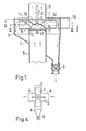
- the separator of Figures 1 to 3 has a rotor 1 which is rotatable about a vertical axis and driven by a motor not shown, via a shaft 2.
- the rotor 1 is encased by a cylindrical housing 3, the bottom of which is shaped like a hopper 4 leading e.g. to an outlet sluice 5.
- a pipe 6 for supplying unsorted material suspended in a carrier gas to the separator leads to a central opening 7 in a bottom plate 8 of the rotor, whereas at the top of the housing 3 there is a second pipe 9 for carrying away a fine fraction of the material separated in the rotor.
- This pipe 9 leads from a central outlet opening 10 in a top plate 11 of the rotor.
- the rotor has substantially radial vanes 12.
- the openings 13 and 14 are formed in frustoconical hubs projecting from the plates 8 and 11 and integral with one another.
- the hubs may be formed by cutting a substantially circular plate to form flaps 17 and 18, which are alternately bent upwards and downwards between respective pairs of adjacent vanes out of the plane of a common hub disc 19, and the edges of which are welded to the vanes 12 and plates 8 or 11.
- the hub disc 19 provides the connection of the rotor to the shaft 2.
- the frustoconical hubs provide a smooth flow path for the suspension into and out of the rotor.
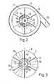
- the left side of the Figure shows the rotor seen from the top towards the plate 11 with the outlet openings 14, which for the sake of clarity are double-hatched and which open from the interior of the rotor up towards the reader, while the right side of the figure shows the rotor without the top plate 11 so that the bottom plate 8 can be seen with its inlet openings 13, which for the sake of clarity are hatched and which open from the interior of the rotor away from the reader.
- the separator shown operates in the following way.
- the material to be sorted is supplied, suspended in carrier gas, through the pipe 6 from where the suspension flows into the rotor via the opening 7 and further out into every second vane interspace through the openings 13 as indicated by solid arrows in Figure 1.
- a first separation of the material takes place by the radial outflow through every second vane interspace, by which the heavy grains in known manner by a combined action from the gas flow and from the centrifugal force provided by the rotor are flung towards the encasing housing 3, down the inner wall of which the coarser grains fall towards the outlet sluice 5 as indicated by dotted arrows in Figure 1.
- the separator may have a tangentially oriented gas supply pipe 15 as shown in Figure 1 and 2.
- FIG 3 is indicated how additional, possibly shorter, vanes 16 may be mounted in the interspaces between the vanes 12.
- These additonal vanes 16 may, as shown to the left in Figure 3, be mounted in each vane interspace 12-12 to increase the efficiency of the rotor or, as shown to the right in Figure 3, only in some of the vane interspaces 12-12, by which it is possible further to influence the known and unavoidable distribution of a separator feed into a fine fraction and a coarse fraction.
Applications Claiming Priority (2)
| Application Number | Priority Date | Filing Date | Title |
|---|---|---|---|
| GB8415190 | 1984-06-14 | ||
| GB848415190A GB8415190D0 (en) | 1984-06-14 | 1984-06-14 | Separator |
Publications (3)
| Publication Number | Publication Date |
|---|---|
| EP0164859A2 true EP0164859A2 (de) | 1985-12-18 |
| EP0164859A3 EP0164859A3 (en) | 1986-03-19 |
| EP0164859B1 EP0164859B1 (de) | 1987-12-02 |
Family
ID=10562427
Family Applications (1)
| Application Number | Title | Priority Date | Filing Date |
|---|---|---|---|
| EP85303034A Expired EP0164859B1 (de) | 1984-06-14 | 1985-04-29 | Sichter |
Country Status (9)
| Country | Link |
|---|---|
| US (1) | US4636302A (de) |
| EP (1) | EP0164859B1 (de) |
| JP (1) | JPS614581A (de) |
| BR (1) | BR8502834A (de) |
| DE (1) | DE3561091D1 (de) |
| ES (1) | ES8607746A1 (de) |
| GB (1) | GB8415190D0 (de) |
| IN (1) | IN165176B (de) |
| MX (1) | MX161683A (de) |
Cited By (1)
| Publication number | Priority date | Publication date | Assignee | Title |
|---|---|---|---|---|
| WO2020152035A1 (de) * | 2019-01-25 | 2020-07-30 | Khd Humboldt Wedag Gmbh | Steigrohrsichter |
Families Citing this family (2)
| Publication number | Priority date | Publication date | Assignee | Title |
|---|---|---|---|---|
| FR2741286B1 (fr) * | 1995-11-21 | 1998-01-23 | Fcb | Separateur a air a action centrifuge |
| DE102008038776B4 (de) | 2008-08-12 | 2016-07-07 | Loesche Gmbh | Verfahren zur Sichtung eines Mahlgut-Fluid-Gemisches und Mühlensichter |
Citations (4)
| Publication number | Priority date | Publication date | Assignee | Title |
|---|---|---|---|---|
| DE2036891A1 (en) * | 1970-07-24 | 1972-02-17 | Hosokawa Funtaikogaku Kenkyusho, Osaka (Japan) | Powder separator - having two sets of rotating vanes |
| DE2225258B1 (de) * | 1972-05-24 | 1973-02-08 | Wessel, Josef, Prof Dr Ing , 8131 Aufkirchen | Rotor fuer fliehkraftsichter |
| DE2817725A1 (de) * | 1978-04-22 | 1979-11-08 | Polysius Ag | Windsichter |
| DE3044063A1 (de) * | 1980-11-22 | 1982-07-15 | Krupp Polysius Ag, 4720 Beckum | Windsichter |
Family Cites Families (13)
| Publication number | Priority date | Publication date | Assignee | Title |
|---|---|---|---|---|
| GB301765A (en) * | 1927-09-01 | 1928-12-03 | Simon Ltd Henry | Improvements relating to the purification of cereal products |
| DE894803C (de) * | 1947-02-07 | 1953-10-29 | Alpine A G Eisengiesserei | Vorrichtung und Verfahren zur Windsichtung |
| BE482847A (de) * | 1947-06-26 | |||
| GB694219A (en) * | 1948-10-01 | 1953-07-15 | Alpine Ag Eisengiesserei Und M | Improvements in centrifugal flow separators |
| US2753996A (en) * | 1952-01-17 | 1956-07-10 | Alpine Ag | Flow separators |
| DE940447C (de) * | 1954-03-27 | 1956-03-15 | Alpine Aktien Ges | Windsichter |
| US2939579A (en) * | 1956-07-13 | 1960-06-07 | Hardinge Harlowe | Air classifier |
| US3670886A (en) * | 1970-08-05 | 1972-06-20 | Hosokawa Funtaikogaku Kenkyush | Powder classifier |
| SU563197A1 (ru) * | 1974-05-06 | 1977-06-30 | Предприятие П/Я Г-4392 | Центробежный сепаратор |
| GB2041251B (en) * | 1978-11-24 | 1982-10-20 | Hosolawa Funtai Kogaku Kenkyus | Pneumatic classifier |
| JPS5728306A (en) * | 1980-07-28 | 1982-02-16 | Fujitsu Ltd | Method of indexing and treating terminal resistance of printed board |
| SU940878A1 (ru) * | 1980-08-01 | 1982-07-07 | Институт технической теплофизики АН УССР | Центробежный классификатор |
| GB2110962B (en) * | 1981-12-10 | 1985-08-14 | Greville Nicolas Whiddett | Powder classifier |
-
1984
- 1984-06-14 GB GB848415190A patent/GB8415190D0/en active Pending
-
1985
- 1985-04-29 DE DE8585303034T patent/DE3561091D1/de not_active Expired
- 1985-04-29 EP EP85303034A patent/EP0164859B1/de not_active Expired
- 1985-05-02 IN IN337/MAS/85A patent/IN165176B/en unknown
- 1985-05-15 US US06/734,451 patent/US4636302A/en not_active Expired - Fee Related
- 1985-06-03 ES ES543823A patent/ES8607746A1/es not_active Expired
- 1985-06-10 JP JP60125953A patent/JPS614581A/ja active Granted
- 1985-06-13 BR BR8502834A patent/BR8502834A/pt not_active IP Right Cessation
- 1985-06-14 MX MX205659A patent/MX161683A/es unknown
Patent Citations (4)
| Publication number | Priority date | Publication date | Assignee | Title |
|---|---|---|---|---|
| DE2036891A1 (en) * | 1970-07-24 | 1972-02-17 | Hosokawa Funtaikogaku Kenkyusho, Osaka (Japan) | Powder separator - having two sets of rotating vanes |
| DE2225258B1 (de) * | 1972-05-24 | 1973-02-08 | Wessel, Josef, Prof Dr Ing , 8131 Aufkirchen | Rotor fuer fliehkraftsichter |
| DE2817725A1 (de) * | 1978-04-22 | 1979-11-08 | Polysius Ag | Windsichter |
| DE3044063A1 (de) * | 1980-11-22 | 1982-07-15 | Krupp Polysius Ag, 4720 Beckum | Windsichter |
Cited By (1)
| Publication number | Priority date | Publication date | Assignee | Title |
|---|---|---|---|---|
| WO2020152035A1 (de) * | 2019-01-25 | 2020-07-30 | Khd Humboldt Wedag Gmbh | Steigrohrsichter |
Also Published As
| Publication number | Publication date |
|---|---|
| EP0164859B1 (de) | 1987-12-02 |
| DE3561091D1 (en) | 1988-01-14 |
| EP0164859A3 (en) | 1986-03-19 |
| ES543823A0 (es) | 1986-06-01 |
| GB8415190D0 (en) | 1984-07-18 |
| JPH052393B2 (de) | 1993-01-12 |
| ES8607746A1 (es) | 1986-06-01 |
| BR8502834A (pt) | 1986-02-25 |
| JPS614581A (ja) | 1986-01-10 |
| IN165176B (de) | 1989-08-26 |
| US4636302A (en) | 1987-01-13 |
| MX161683A (es) | 1990-12-11 |
Similar Documents
| Publication | Publication Date | Title |
|---|---|---|
| EP0204412B2 (de) | Sichter zum Sortieren von Materialpartikeln | |
| US4799595A (en) | Apparatus for the classifying of powdered bulk materials | |
| CA1249245A (en) | Particle classifier | |
| US4528091A (en) | Particle classifier | |
| US5158182A (en) | Sifter | |
| US3928188A (en) | Screening arrangement | |
| EP0171987B1 (de) | Abscheider zum Trennen von Partikelmaterial | |
| US5511668A (en) | Pneumatic sifter | |
| US4689140A (en) | Separator for sorting particulate material | |
| US4693811A (en) | Sifter | |
| US2753996A (en) | Flow separators | |
| PL155036B1 (en) | Separator,especially rotary for separating a mix of wood chops and a method for separating wood chops | |
| EP0164859B1 (de) | Sichter | |
| CN113950364B (zh) | 旋风式空气过滤装备 | |
| EP0149221B1 (de) | Sortierer | |
| EP0073567B1 (de) | Verfahren und Vorrichtung zum Sortieren von partikelförmigem Material | |
| EP0519535A1 (de) | Dynamischer Sichter für pulverförmige Materialien, insbesondere Zement und eine einen solchen enthaltende Anlage | |
| US3891543A (en) | Centrifugal sifter apparatus | |
| US2915179A (en) | Aerodynamic classifier | |
| US2598032A (en) | Wet separator for purifying a particle laden gas current | |
| EP1398086B1 (de) | Partikelsortierer | |
| AU623940B2 (en) | Separator for sorting particulate material | |
| US1085256A (en) | Ore-separator. | |
| WO1994025184A1 (en) | Separator for sorting of particulate material | |
| JPS6044031B2 (ja) | 粉末分級装置用分級羽根車の構造 |
Legal Events
| Date | Code | Title | Description |
|---|---|---|---|
| PUAI | Public reference made under article 153(3) epc to a published international application that has entered the european phase |
Free format text: ORIGINAL CODE: 0009012 |
|
| AK | Designated contracting states |
Designated state(s): BE DE FR GB IT |
|
| PUAL | Search report despatched |
Free format text: ORIGINAL CODE: 0009013 |
|
| AK | Designated contracting states |
Kind code of ref document: A3 Designated state(s): BE DE FR GB IT |
|
| 17P | Request for examination filed |
Effective date: 19860819 |
|
| 17Q | First examination report despatched |
Effective date: 19870319 |
|
| ITF | It: translation for a ep patent filed |
Owner name: DR. ING. A. RACHELI & C. |
|
| GRAA | (expected) grant |
Free format text: ORIGINAL CODE: 0009210 |
|
| AK | Designated contracting states |
Kind code of ref document: B1 Designated state(s): BE DE FR GB IT |
|
| REF | Corresponds to: |
Ref document number: 3561091 Country of ref document: DE Date of ref document: 19880114 |
|
| ET | Fr: translation filed | ||
| PLBE | No opposition filed within time limit |
Free format text: ORIGINAL CODE: 0009261 |
|
| STAA | Information on the status of an ep patent application or granted ep patent |
Free format text: STATUS: NO OPPOSITION FILED WITHIN TIME LIMIT |
|
| 26N | No opposition filed | ||
| ITTA | It: last paid annual fee | ||
| PGFP | Annual fee paid to national office [announced via postgrant information from national office to epo] |
Ref country code: FR Payment date: 19970409 Year of fee payment: 13 |
|
| PGFP | Annual fee paid to national office [announced via postgrant information from national office to epo] |
Ref country code: GB Payment date: 19970421 Year of fee payment: 13 |
|
| PGFP | Annual fee paid to national office [announced via postgrant information from national office to epo] |
Ref country code: DE Payment date: 19970505 Year of fee payment: 13 |
|
| PGFP | Annual fee paid to national office [announced via postgrant information from national office to epo] |
Ref country code: BE Payment date: 19970612 Year of fee payment: 13 |
|
| PG25 | Lapsed in a contracting state [announced via postgrant information from national office to epo] |
Ref country code: GB Free format text: LAPSE BECAUSE OF NON-PAYMENT OF DUE FEES Effective date: 19980429 |
|
| PG25 | Lapsed in a contracting state [announced via postgrant information from national office to epo] |
Ref country code: FR Free format text: THE PATENT HAS BEEN ANNULLED BY A DECISION OF A NATIONAL AUTHORITY Effective date: 19980430 Ref country code: BE Free format text: LAPSE BECAUSE OF NON-PAYMENT OF DUE FEES Effective date: 19980430 |
|
| BERE | Be: lapsed |
Owner name: F.L. SMIDTH & CO. A/S Effective date: 19980430 |
|
| GBPC | Gb: european patent ceased through non-payment of renewal fee |
Effective date: 19980429 |
|
| PG25 | Lapsed in a contracting state [announced via postgrant information from national office to epo] |
Ref country code: DE Free format text: LAPSE BECAUSE OF NON-PAYMENT OF DUE FEES Effective date: 19990202 |
|
| REG | Reference to a national code |
Ref country code: FR Ref legal event code: ST |