EP0163866A1 - Decken- und Wandkonstruktion - Google Patents
Decken- und Wandkonstruktion Download PDFInfo
- Publication number
- EP0163866A1 EP0163866A1 EP85104450A EP85104450A EP0163866A1 EP 0163866 A1 EP0163866 A1 EP 0163866A1 EP 85104450 A EP85104450 A EP 85104450A EP 85104450 A EP85104450 A EP 85104450A EP 0163866 A1 EP0163866 A1 EP 0163866A1
- Authority
- EP
- European Patent Office
- Prior art keywords
- stones
- bearing
- ceiling
- center
- wall construction
- Prior art date
- Legal status (The legal status is an assumption and is not a legal conclusion. Google has not performed a legal analysis and makes no representation as to the accuracy of the status listed.)
- Granted
Links
- 238000010276 construction Methods 0.000 title claims abstract description 24
- 239000004575 stone Substances 0.000 claims abstract description 113
- 239000010437 gem Substances 0.000 claims description 4
- 238000001816 cooling Methods 0.000 description 8
- 230000006378 damage Effects 0.000 description 2
- 238000002485 combustion reaction Methods 0.000 description 1
- 238000010304 firing Methods 0.000 description 1
- 238000010438 heat treatment Methods 0.000 description 1
- 238000004519 manufacturing process Methods 0.000 description 1
- 238000007789 sealing Methods 0.000 description 1
Images

Classifications
-
- F—MECHANICAL ENGINEERING; LIGHTING; HEATING; WEAPONS; BLASTING
- F27—FURNACES; KILNS; OVENS; RETORTS
- F27D—DETAILS OR ACCESSORIES OF FURNACES, KILNS, OVENS OR RETORTS, IN SO FAR AS THEY ARE OF KINDS OCCURRING IN MORE THAN ONE KIND OF FURNACE
- F27D1/00—Casings; Linings; Walls; Roofs
- F27D1/14—Supports for linings
-
- F—MECHANICAL ENGINEERING; LIGHTING; HEATING; WEAPONS; BLASTING
- F27—FURNACES; KILNS; OVENS; RETORTS
- F27D—DETAILS OR ACCESSORIES OF FURNACES, KILNS, OVENS OR RETORTS, IN SO FAR AS THEY ARE OF KINDS OCCURRING IN MORE THAN ONE KIND OF FURNACE
- F27D1/00—Casings; Linings; Walls; Roofs
- F27D1/02—Crowns; Roofs
-
- F—MECHANICAL ENGINEERING; LIGHTING; HEATING; WEAPONS; BLASTING
- F27—FURNACES; KILNS; OVENS; RETORTS
- F27D—DETAILS OR ACCESSORIES OF FURNACES, KILNS, OVENS OR RETORTS, IN SO FAR AS THEY ARE OF KINDS OCCURRING IN MORE THAN ONE KIND OF FURNACE
- F27D1/00—Casings; Linings; Walls; Roofs
- F27D1/04—Casings; Linings; Walls; Roofs characterised by the form, e.g. shape of the bricks or blocks used
Definitions
- the invention relates to a ceiling and wall construction for the gas-tight lining of a room exposed to high temperatures, according to the preamble of claim 1.
- Ceiling and wall constructions of the required type are used in particular for heat exchanger devices, e.g. Preheaters, ovens and coolers of heat treatment devices and systems, also used for firing rooms and for lines and the like, in order to gas-tightly line their rooms, which are exposed to relatively high and possibly changing temperatures.
- heat exchanger devices e.g. Preheaters, ovens and coolers of heat treatment devices and systems
- firing rooms and for lines and the like also used for firing rooms and for lines and the like, in order to gas-tightly line their rooms, which are exposed to relatively high and possibly changing temperatures.
- a number of very differently designed ceiling and wall constructions for the rooms mentioned are known.
- Carried in such a known and initially presupposed embodiments are of parallel and spaced from one another extending support rails to close rows disposed sequentially jewels, wherein between every two adjacent L agersteinhall, an intermediate space is formed, which is filled by so-called.
- Means stones which each subordinate also to rows and are inserted sealingly in the space mentioned.
- These center stones and the bearing stones supporting them, arranged in adjacent rows, have on their mutually facing side surfaces exactly matched wing profiles, the Center stones in the transverse direction running between the associated bearing stones have a cross-section tapered towards the interior of the space to be lined.
- each center stone which face adjacent center stones, on the other hand, run approximately perpendicularly and parallel to one another, but they have tongue and groove configurations, so that mutually adjacent center stones engage in one another. It is now necessary for various reasons to replace damaged or destroyed stones with new ones. Such a replacement of stones is only possible with the known construction described above, however, if entire stone groups of the ceiling and wall construction are removed, but this is not possible without the damage or destruction of further stones.
- the invention is therefore based on the object to provide a ceiling and wall construction of the type required in the preamble of claim 1, which allows simple and quick replacement of individual stones without damaging other stones.
- the center stones not only the center stones, but also additional ones are in the space between two adjacent rows of jewels Lich also used gas-tight between two adjacent center stones supporting stones.
- These supporting stones are shaped and profiled in such a way that they can be received and carried by the corresponding bearing stones in the same way as the central stones, while on the other hand they are profiled on the side surfaces facing the central stones so that the central stones are both in the gaps between adjacent rows of jewels as well as in the gaps between adjacent supporting stones can be taken up exactly.
- the illustrated embodiment relates only to a suspended ceiling for a heat exchanger space, ins special for a radiator housing, however, ß but in the same way other heat exchange rooms, combustion chambers, ducts, lines and the like can be lined gas-tight.
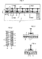
- the suspended ceiling 1 shown in FIG. 1 in partial longitudinal section is assigned to the housing of a cooler, for example a grate cooler or the like for burned goods, the cooling space 2 of which is lined gas-tight by this suspended ceiling 1.
- the suspended ceiling 1 is composed of parallel and spaced-apart mounting rails 3, bearing stones 4 carried by it, which are arranged in tight rows 5a, 5b on the mounting rails 3, and supporting stones 6 and center stones 7 fitted between the rows 5a, 5b of the bearing stones into one unit composed.
- the mounting rails 3 which can be or can be fastened with their upper ends to an outer housing structure which is only indicated, are arranged in a hanging manner and, as shown in FIG. 1, are T-shaped with two in their lower end sections which engage with the bearing stones 4 Side flanges 8a and 8b formed.
- the bearing stones 4 each have an outwardly open recess 9 on their side faces opposite the center stones 7 or supporting stones 6, which extend over the entire length of the bearing stones 4 and in which the associated side flange 8a or 8b of the corresponding mounting rail 3 engages to such an extent that the bearing blocks 4 are reliably held on these side flanges 8a, 8b, but the side surface areas which lie below these side flanges 8a, 8b and face one another are arranged on a mounting rail 3
- the bearing stones of both rows 5a and 5b are gas-tight (see Fig. 1).
- each bearing stone row 5a, 5b also have interlocking tongue and groove designs on their mutually facing side surfaces, as illustrated in FIG. 3, so that the bearing stones 4 arranged in a row 5a, 5b also in a direction parallel to the mounting rail 3 are put together reliably and gas-tight.
- the bearing stones 4 each have a wing profiling 12 on their side surface facing the intermediate space 11 (that is, facing away from the mounting rails 3), which in the exemplary embodiment shown runs obliquely downwards (towards the cooling space 2) in such a way that that each bearing 4 is a downward increasing Has cross-sectional shape (see Fig. 1).
- the rectangular, preferably square, central stones 7 (FIGS. 2 and 5c) have on two opposite side surfaces 7a and 7b a counter-profile that matches the wing profiling 12 of the bearing stones 4 and, in this transverse direction, a transverse dimension that exactly adjoins the space 11 between them Row of rows 5a and 5b corresponds.
- the central stones tapering in cross-section in the direction of the interior of the cooling space 2 to be lined are fitted exactly and in a gas-tight manner between two adjacent rows of bearing stones 5a, 5b.
- each center stone 7 has a second counter-profiling on its two other side surfaces 7c and 7d, which extend at right angles to the side surfaces 7a and 7b, which may preferably have the same profile shape as the first counter-profiling on the side surfaces 7a, 7b, so that each center stone has the shape has a straight truncated pyramid with square bases, of which the small base 7f points into the interior of the cooling space 2.
- 6a to 6c show the shape of the supporting stones 6, according to which the cross section of each supporting stone 6 tapers in the cross-sectional direction running between the bearing stones 4, that is to say between its side surfaces 6a and 6b, towards the inside of the cooling space 2 to be clad, during the supporting stone cross section tapers in the cross-sectional direction running between the center stones 7, that is to say between its side surfaces 6c and 6d, towards the outside of the cooling space 2, that is to say in the opposite direction.
- the supporting stones 6 can in the same way as the central blocks 7 in the intermediate space 1 1 between the bearing blocks 4 appropriately and gas-tightly received and supported, while at the same part, with its airfoil profiling on the side surfaces 6c and 6d reliable, gas-tight support for the form the corresponding center stones (see in particular Fig. 1, 2 and 4).
- the drawing figures 1, 3 and 4 also clearly show that the bearing stones 4, the supporting stones 6 and the center stones 7 all have the same height H. point. Furthermore, it is advantageous for a reliable mounting and gas-tight arrangement of the stones if all stones 4, 6, 7 have coordinated horizontal wings 13 within their profiles, at least in the middle height range and lying at the same height.
- the bearing blocks 4, the supporting stones 6 and the center stones 7 are arranged flush with one another with their inner sides facing the interior of the cooling space 2.
- the assembly of the ceiling structure is carried out in a simple manner as follows: on the side flanges 8a, 8b of the mounting rails mounted in parallel and with the required spacing from one another, the bearing blocks 4 first become dense rows 5a, 5b arranged (to a certain extent threaded), as can be seen from FIGS. 1, 2 and 3. Then the supporting stones 6 and then the center stones 7 are inserted into the spaces 11 from above, so that the reliable load-bearing and gastight sealing suspended ceiling results.
Landscapes
- Engineering & Computer Science (AREA)
- Mechanical Engineering (AREA)
- General Engineering & Computer Science (AREA)
- Finishing Walls (AREA)
- Furnace Housings, Linings, Walls, And Ceilings (AREA)
- Building Environments (AREA)
Abstract
Description
- Die Erfindung betrifft eine Decken- und Wandkonstruktion zur gasdichten Auskleidung eines hohen Temperaturen ausgesetzten Raumes, gemäß dem Oberbegriff des Anspruches 1.
- Decken- und Wandkonstruktionen der vorausgesetzten Art werden insbesondere für Wärmetauschereinrichtungen, z.B. Vorwärmer, öfen und Kühler von Wärmebehandlungsvorrichtungen und -anlagen, ferner für Feuerungsräume sowie für Leitungen und dergleichen verwendet, um deren Räume gasdicht auszukleiden, die relativ hohen und gegebenenfalls sich ändernden Temperaturen ausgesetzt sind. Aus der Praxis ist eine Reihe von sehr verschieden ausgeführten Decken- und Wandkonstruktionen für die genannten Räume bekannt.
- Bei einer solchen bekannten und eingangs vorausgesetzten Ausführungsformwerden von parallel und mit Abstand zueinander verlaufenden Halterungsschienen zu dichten Reihen aneinander angeordnete Lagersteine getragen, wobei zwischen je zwei einander benachbarten Lagersteinreihen ein Zwischenraum gebildet ist, der von sog. Mittelsteinen ausgefüllt ist, die ebenfalls zu Reihen aneinandergeordnet und dichtend in den genannten Zwischenraum eingesetzt sind. Diese Mittelsteine und die sie abstützenden, in benachbarten Reihen angeordneten Lagersteine besitzen an ihren einander zugewandten Seitenflächen genau aneinander angepaßte Tragflächenprofilierungen, wobei die Mittelsteine in der zwischen den zugehörigen Lagersteinen verlaufenden Querrichtung einen zum Innern des auszukleidenden Raumes verjüngten Querschnitt besitzen. Die beiden anderen, jeweils benachbarten Mittelsteinen zugewandten Seitenflächen jedes Mittelsteines verlaufen dagegen etwa senkrecht und parallel zueinander, wobei sie jedoch Nut- und Federausbildungen aufweisen, so daß jeweils einander benachbarte Mittelsteine ineinandergreifen. Es ist nun aus verschiedensten Gründen immer wieder erforderlich, beschädigte oder zerstörte Steine durch neue zu ersetzen. Ein solches Auswechseln von Steinen ist bei der zuvor geschilderten bekannten Konstruktion jedoch nur möglich, wenn ganze Steingruppen der Decken-und Wandkonstruktion herausgenommen werden, was jedoch nicht ohne die Beschädigung oder Zerstörung weiterer Steine möglich ist.
- Der Erfindung liegt daher die Aufgabe zugrunde, eine Decken- und Wandkonstruktion der im Oberbegriff des Anspruches 1 vorausgesetzten Art zu schaffen, die ein einfaches und rasches Auswechseln einzelner Steine gestattet, ohne daß dazu weitere Steine beschädigt werden.
- Diese Aufgabe wird erfindungsgemäß durch die im Kennzeichen des Anspruches 1 angegebenen Merkmale gelöst.
- Nach der vorliegenden Erfindung werden in den zwischen zwei benachbarten Lagersteinreihen vorhandenen Zwischenraum nicht nur die Mittelsteine, sondern zusätzlich auch noch zwischen je zwei einander benachbarten Mittelsteinen Tragsteine gasdicht eingesetzt. Diese Tragsteine sind dabei so geformt und profiliert, daß sie zum einen in der gleichen Weise wie die Mittelsteine von den entsprechenden Lagersteinen aufgenommen und getragen werden können, während sie zum andern ihrerseits an den den Mittelsteinen zugewandten Seitenflächen so profiliert sind, daß die Mittelsteine sowohl in die Zwischenräume zwischen benachbarten Lagersteinreihen als auch in die Zwischenräume benachbarter Tragsteine genau passend aufgenommen werden können. Aufgrund dieser Ausbildung sowie aufgrund der Pyramidenstumpfform der Mittelsteine ist es somit auf einfache Weise möglich, eine Decken- oder Wandkonstruktion gewissermaßen baukastenmäßig so herzustellen, daß auf den Halterungsschienen zunächst die Lagersteine aufgereiht werden, in die genannten Zwischenräume zweier benachbarter Lagersteinreihen die Tragsteine mit entsprechenden Abständen von der Außenseite des auszukleidenden Raumes her eingesetzt werden und daß danach in die gebildeten Zwischenräume zwischen den Lagersteinreihen und benachbarten Tragsteinen die Mittelsteine ebenfalls von der Außenseite des auszukleidenden Raumes her genau passend eingesetzt werden. Das Herausnehmen (zum Auswechseln eines beschädigten Steines) geschieht in umgekehrter Reihenfolge ebenfalls in äußerst einfacher Weise, so daß ein beliebiger Stein ohne Zerstörung anderer Steine einzeln ausgewechselt werden kann. Aufgrund der einander angepaßten Profilierungen der Seitenflächen aller Steine ergibt sich eine vollkommen gasdichte Auskleidung des entsprechenden Raumes.
- Die Erfindung sei im folgenden anhand eines in der Zeichnung veranschaulichten Ausführungsbeispieles näher beschrieben. In der sehr schematisch gehaltenen Zeichnung zeigen
- Fig.1 eine Teil-Längsschnittansicht durch einen mit der erfindungsgemäßen Konstruktion (als Deckenkonstruktion) ausgekleideten Raumes;
- Fig.2 eine Teil-Aufsicht auf die Deckenkonstruktion gemäß Fig.1;
- Fig.3 eine Teil-Querschnittsansicht entlang der Linie 111-111 in Fig.1;
- Fig.4 eine Querschnittsansicht entlang der Linie IV-IV in Fig. 1;
- Fig.5a, 5b und 5c Vorderansicht, Seitenansicht und Grundriß eines Mittelsteines;
- Fig.6a, 6b und 6c Vorderansicht, Seitenansicht und Grundriß eines Tragsteines.
- Bevor auf die Einzelheiten des in der Zeichnung veranschaulichten Ausführungsbeispieles der Decken- und Wandkonstruktion eingegangen wird, sei betont, daß die veranschaulichte Ausführungsform sich lediglich auf eine Hängedecke für einen Wärmetauscherraum, insbesondere für ein Kühlergehäuse bezieht, daß jedoch in gleicher Weise auch andere Wärmetauscherräume, Feuerräume, Kanäle, Leitungen und dergleichen gasdicht ausgekleidet werden können.
- Die in Fig.1 im Teil-Längsschnitt dargestellte Hängedecke 1 ist dem Gehäuse eines Kühlers zugeordnet, beispielsweise eines Rostkühlers oder dergleichen für gebranntes Gut, dessen Kühlraum 2 durch diese Hängedecke 1 gasdicht ausgekleidet ist.
- Die Hängedecke 1 ist aus parallel und mit Abstand zueinander verlaufenden Halterungsschienen 3, davon getragenen Lagersteinen 4, die zu dichten Reihen 5a, 5b auf den Halterungsschienen 3 angeordnet sind, sowie aus zwischen den Lagersteinreihen 5a, 5b eingepaßten Tragsteinen 6 und Mittelsteinen 7 zu einer Einheit zusammengesetzt.
- Die Halterungsschienen 3, die mit ihren oberen Enden an einem nur angedeuteten äußeren Gehäuseaufbau befestigt sein bzw. werden können, sind hängend angeordnet und in ihren mit den Lagersteinen 4 in Eingriff stehenden unteren Endabschnitten - wie in Fig.1 gezeigt - T-förmig mit zwei Seitenflanschen 8a und 8b ausgebildet.
- In Fig.1 ist auch zu erkennen, daß die Lagersteine 4 an ihren den Mittelsteinen 7 bzw. Tragsteinen 6 entgegengesetzten Seitenflächen je eine nach außen hin offene Aussparung 9 aufweisen, die sich über die ganze Länge der Lagersteine 4 erstrecken und in die der zugehörige Seitenflansch 8a bzw. 8b der entsprechenden Halterungsschiene 3 so weit eingreift, daß die Lagersteine 4 zuverlässig auf diesen Seitenflanschen 8a, 8b gehaltert sind, wobei jedoch die unterhalb dieser Seitenflansche 8a, 8b liegenden, einander zugewandten Seitenflächenbereiche der auf einer Halterungsschiene 3 angeordneten Lagersteine beider Lagersteinreihen 5a und 5b gasdicht aneinanderliegen (vgl. Fig.1).
- Die Lagersteine 4 jeder Lagersteinreihe 5a, 5b weisen ferner an ihren einander zugewandten Seitenflächen ineinandergreifende Nut- und Federausbildungen auf, wie es in Fig.3 veranschaulicht ist, so daß die in einer Reihe 5a, 5b angeordneten Lagersteine 4 auch in einer Richtung parallel zur Halterungsschiene 3 zuverlässig und gasdicht aneinandergesetzt sind.
- Im Bereich zwischen je zwei einander benachbarten Halterungsschienen 3 bilden die dort gehalterten, parallel und mit Abstand voneinander angeordneten Lagersteinreihen 5a und 5b einen Zwischenraum 11, in den - wie oben erwähnt - die Tragsteine 6 und Mittelsteine 7 eingepaßt sind. Zur Aufnahme dieser Trag- und Mittelsteine 6, 7 weisen die Lagersteine 4 an ihrer dem Zwischenraum 11 zugewandten (also den Halterungsschienen 3 abgewandten) Seitenfläche jeweils eine Tragflächenprofilierung 12 auf, die im dargestellten Ausführungsbeispiel schräg nach unten (zum Kühlraum 2 hin) derart verläuft, daß jeder Lagerstein 4 eine nach unten zunehmende Querschnittsform besitzt (vgl. Fig.1).
- Die im Grundriß rechteckigen, vorzugsweise quadratischen Mittelsteine 7 (Fig.2 und 5c) besitzen an zwei einander gegenüberliegenden Seitenflächen 7a und 7b eine mit der Tragflächenprofilierung 12 der Lagersteine 4 zusammenpassende Gegenprofilierung und in dieser Querrichtung eine Querabmessung, die genau dem Zwischenraum 11 zwischen einander benachbarten Lagersteinreihen 5a und 5b entspricht. Auf diese Weise sind die sich im Querschnitt in Richtung auf das Innere des auszukleidenden Kühlraumes 2 verjüngenden Mittelsteine genau passend und gasdicht zwischen zwei einander benachbarten Lagersteinreihen 5a, 5b eingepaßt.
- Jeder Mittelstein 7 weist jedoch an seinen rechtwinklig zu den Seitenflächen 7a und 7b verlaufenden beiden anderen Seitenflächen 7c und 7d eine zweite Gegenprofilierung auf, die vorzugsweise die gleiche Proilform wie die erste Gegenprofilierung an den Seitenflächen 7a, 7b aufweisen kann, so daß jeder Mittelstein die Form eines geraden Pyramidenstumpfes mit quadratischen Grundflächen besitzt, von denen die kleine Grundfläche 7f in das Innere des Kühlraumes 2 weist.
- Auch die ebenfalls in den Zwischenraum 11 eingepaßten und zwischen je zwei einander benachbarten Mittelsteinen 7 eingepaßten Tragsteine 6 weisen an ihren den Lagersteinen 4 zugewandten ersten Seitenflächen 6a und 6b eine der Tragflächenprofilierung 12 dieser Tragsteine 4 angepaßte Seitenprofilierung auf. An ihren den Mittelsteinen 7 zugewandten zweiten Seitenflächen 6c und 6d weisen die Tragsteine 6 dagegen eine den zweiten Gegenprofilierungen der Mittelsteine 7 angepaßte Tragflächenprofilierung auf, die damit im vorliegenden Ausführungsbeispiel die gleiche Profilform wie die Tragflächenprofilierung 12 der Lagersteine 4 besitzt. Die Figuren 6a bis 6c zeigen die Formgebung der Tragsteine 6, wonach nämlich der Querschnitt jedes Tragsteines 6 sich in der zwischen den Lagersteinen 4, also zwischen seinen Seitenflächen 6a und 6b, verlaufenden Querschnittsrichtung zum Innern des zu verkleidenden Kühlraumes 2 hin verjüngt, während der Tragsteinquerschnitt sich in der zwischen den Mittelsteinen 7, also zwischen seinen Seitenflächen 6c und 6d, verlaufenden Querschnittsrichtung nach der Außenseite des Kühlraumes 2 hin, also entgegengesetzt, verjüngt. Durch diese Querschnittsformen können die Tragsteine 6 in gleicher Weise wie die Mittelsteine 7 im Zwischenraum 11 zwischen den Lagersteinen 4 passend und gasdicht aufgenommen und gehaltert werden, während sie gleichzeitig ihrerseits mit ihrer Tragflächenprofilierung an den Seitenflächen 6c und 6d eine zuverlässige und gasdichte Abstützung für die entsprechenden Mittelsteine bilden (vgl. insbesondere Fig.1, 2 und 4).
- Den Zeichnungsfiguren 1, 3 und 4 ist ferner deutlich zu entnehmen, daß die Lagersteine 4, die Tragsteine 6 und die Mittelsteine 7 alle dieselbe Höhe H aufweisen. Ferner ist es für eine zuverlässige Halterung und gasdichte Zusammenordnung der Steine von Vorteil, wenn alle Steine 4, 6, 7 zumindest im mittleren Höhenbereich sowie auf derselben Höhe liegend aufeinander abgestimmte horizontale Tragflächen 13 innerhalb ihrer Profilierungen besitzen.
- Im zusammengesetzten Zustand sind die Lagersteine 4, die Tragsteine 6 und die Mittelsteine 7 mit ihren dem Innern des Kühlraumes 2 zugewandten Innenseiten bündig zueinander angeordnet.
- Bei der in der Zeichnung veranschaulichten und oben beschriebenen Ausführung der Hängedecke geschieht das Zusammenbauen der Deckenkonstrüktion auf einfache Weise wie folgt: Auf die Seitenflansche 8a, 8b der parallel und mit den erforderlichen Abständen zueinander angebrachten Halterungsschienen werden zunächst die Lagersteine 4 zu dichten Reihen 5a, 5b angeordnet (gewissermaßen aufgefädelt), wie es aus den Fig.1, 2 und 3 ersichtlich ist. Danach werden in die Zwischenräume 11 die Tragsteine 6 und anschließend die Mittelsteine 7 von oben her eingesetzt, so daß sich die zuverlässig tragende und gasdicht abdichtende Hängedecke ergibt.
- Daß durch die erfindungsgemäße Konstruktion auch anders gestaltete Räume als der veranschaulichte Kühlraum 2 gasdicht ausgekleidet werden können, ist bereits weiter oben zum Ausdruck gebracht worden. Des weiteren sei betont, daß die anhand einer Hängedecke beschriebene Konstruktion selbstverständlich nicht nur als reine Deckenkonstruktion, sondern in gleichartiger Weise auch als Wandkonstruktion Verwendung finden kann und daß darüber hinaus selbstverständlich die Decke nicht im wesentlichen horizontal, sondern auch gewölbt oder schräg verlaufen kann.
Claims (6)
dadurch gekennzeichnet,
daß jeder Mittelstein (7) außer an seinen den Lagersteinen (4) zugewandten Seitenflächen (7a, 7b) an seinen rechtwinklig dazu verlaufenden Seitenflächen (7c, 7d) eine zweite Gegenprofilierung aufweist, wobei er im wesentlichen die Form eines Pyramidenstumpfes besitzt, dessen kleine Grundfläche (7f) in das Innere des auszukleidenden Raumes (2) weist, und daß zwischen je zwei in einer Reihe einander benachbarten Mittelsteinen (7) einerseits und zwischen den entsprechenden Lagersteinen (4) andererseits je ein Tragstein (6) dichtend angeordnet ist, dessen den Lagersteinen (4) zugewandten ersten Seitenflächen (6a, 6b) eine der Tragflächenprofilierung (12) dieser Lagersteine angepaßte Profilierung und dessen den Mittelsteinen (7) zugewandten zweiten Seitenflächen (6c, 6d) eine den zweiten Gegenprofilierungen dieser Mittelsteine angepaßte Tragflächenprofilierung aufweisen.
Applications Claiming Priority (2)
| Application Number | Priority Date | Filing Date | Title |
|---|---|---|---|
| DE3418195A DE3418195A1 (de) | 1984-05-16 | 1984-05-16 | Decken- und wandkonstruktion |
| DE3418195 | 1984-05-16 |
Publications (2)
| Publication Number | Publication Date |
|---|---|
| EP0163866A1 true EP0163866A1 (de) | 1985-12-11 |
| EP0163866B1 EP0163866B1 (de) | 1987-06-10 |
Family
ID=6236025
Family Applications (1)
| Application Number | Title | Priority Date | Filing Date |
|---|---|---|---|
| EP85104450A Expired EP0163866B1 (de) | 1984-05-16 | 1985-04-12 | Decken- und Wandkonstruktion |
Country Status (6)
| Country | Link |
|---|---|
| US (1) | US4628657A (de) |
| EP (1) | EP0163866B1 (de) |
| BR (1) | BR8502278A (de) |
| DE (2) | DE3418195A1 (de) |
| ES (1) | ES8607458A1 (de) |
| ZA (1) | ZA853083B (de) |
Cited By (8)
| Publication number | Priority date | Publication date | Assignee | Title |
|---|---|---|---|---|
| EP0405791A1 (de) * | 1989-06-26 | 1991-01-02 | M.H. Detrick Co. | Feuerfeste Backsteinmauer |
| FR2652889A1 (fr) * | 1989-10-10 | 1991-04-12 | Radex Heraklith | Ensemble pour cle de voute. |
| EP0689021A1 (de) * | 1994-06-21 | 1995-12-27 | Höganäs Bjuf Ab | Feuerfeste Decke und Stein dafür |
| DE19509637A1 (de) * | 1995-03-17 | 1996-09-19 | Karrena Gmbh | Hängedecke mit Tragvorrichtungen |
| WO2004109208A2 (en) | 2003-06-04 | 2004-12-16 | Hatch Ltd. | Cooling and support systems for furnace roofs |
| CZ298145B6 (cs) * | 2006-04-21 | 2007-07-04 | Herbst@Jirí | Pecní agregát |
| EP2600091A1 (de) * | 2011-12-02 | 2013-06-05 | Refractory Intellectual Property GmbH & Co. KG | Brückenartige Tragkonstruktion aus feuerfesten keramischen Steinen |
| CN103255256A (zh) * | 2013-05-29 | 2013-08-21 | 新兴铸管股份有限公司 | 可重复使用的混铁炉炉顶的砌筑方法 |
Families Citing this family (36)
| Publication number | Priority date | Publication date | Assignee | Title |
|---|---|---|---|---|
| US5058268A (en) * | 1989-07-20 | 1991-10-22 | Smagner John D | Method of making and repairing a furnace crown |
| US5062249A (en) * | 1989-07-20 | 1991-11-05 | Smagner John D | Furnace crown means and method |
| US5234660A (en) * | 1990-10-10 | 1993-08-10 | Simko & Sons Industrial Refractories, Inc. | Insulating ceramic fiber batting module, anchoring system, ladle cover assembly and method of assembly |
| US5176876A (en) * | 1990-10-10 | 1993-01-05 | Simko & Sons Industrial Refractories Inc. | Insulating ceramic fiber batting module, anchoring system, ladle cover assembly and method of assembly |
| US5317847A (en) * | 1991-09-12 | 1994-06-07 | Scairono Barry J | U-block reinforcing system |
| AT3275U3 (de) * | 1999-08-17 | 2001-07-25 | Gamerith Horst Dipl Ing Dr Tec | Baublockelement und an diesem festlegbare verankerung |
| ES2189585B1 (es) * | 2000-03-14 | 2004-10-16 | Victor Rodriguez Bermejo | Boveda ceramica para horno industrial. |
| FR2818366A1 (fr) * | 2000-12-18 | 2002-06-21 | P A Technologies | Dispositif pour l'ancrage des revetements refractaires sur les parois des fours industriels, et fours equipes de tels dispositifs |
| US20040088929A1 (en) * | 2002-11-12 | 2004-05-13 | Keystone Retaining Wall Systems, Inc. | Landscaping block |
| JP2013537613A (ja) * | 2010-07-08 | 2013-10-03 | ステラ マテリアルズ インコーポレイテッド | 耐火性構造要素 |
| CA2809080C (en) * | 2012-03-14 | 2017-03-07 | Mitek Holdings, Inc. | Mounting arrangement for panel veneer structures |
| US8800241B2 (en) | 2012-03-21 | 2014-08-12 | Mitek Holdings, Inc. | Backup wall reinforcement with T-type anchor |
| US8904730B2 (en) | 2012-03-21 | 2014-12-09 | Mitek Holdings, Inc. | Thermally-isolated anchoring systems for cavity walls |
| US8739485B2 (en) | 2012-06-28 | 2014-06-03 | Mitek Holdings, Inc. | Low profile pullout resistant pintle and anchoring system utilizing the same |
| US8898980B2 (en) | 2012-09-15 | 2014-12-02 | Mitek Holdings, Inc. | Pullout resistant pintle and anchoring system utilizing the same |
| US8839581B2 (en) | 2012-09-15 | 2014-09-23 | Mitek Holdings, Inc. | High-strength partially compressed low profile veneer tie and anchoring system utilizing the same |
| CN102944114A (zh) * | 2012-12-11 | 2013-02-27 | 开泰镁业有限公司 | 大型悬挂式平炉顶还原炉 |
| US8881488B2 (en) | 2012-12-26 | 2014-11-11 | Mitek Holdings, Inc. | High-strength ribbon loop anchors and anchoring systems utilizing the same |
| US9038351B2 (en) | 2013-03-06 | 2015-05-26 | Columbia Insurance Company | Thermally coated wall anchor and anchoring systems with in-cavity thermal breaks for cavity walls |
| US8863460B2 (en) * | 2013-03-08 | 2014-10-21 | Columbia Insurance Company | Thermally coated wall anchor and anchoring systems with in-cavity thermal breaks |
| US8978326B2 (en) | 2013-03-12 | 2015-03-17 | Columbia Insurance Company | High-strength partition top anchor and anchoring system utilizing the same |
| US8833003B1 (en) | 2013-03-12 | 2014-09-16 | Columbia Insurance Company | High-strength rectangular wire veneer tie and anchoring systems utilizing the same |
| US8910445B2 (en) | 2013-03-13 | 2014-12-16 | Columbia Insurance Company | Thermally isolated anchoring system |
| US8844229B1 (en) | 2013-03-13 | 2014-09-30 | Columbia Insurance Company | Channel anchor with insulation holder and anchoring system using the same |
| US9260857B2 (en) | 2013-03-14 | 2016-02-16 | Columbia Insurance Company | Fail-safe anchoring systems for cavity walls |
| US8904726B1 (en) | 2013-06-28 | 2014-12-09 | Columbia Insurance Company | Vertically adjustable disengagement prevention veneer tie and anchoring system utilizing the same |
| US8978330B2 (en) | 2013-07-03 | 2015-03-17 | Columbia Insurance Company | Pullout resistant swing installation tie and anchoring system utilizing the same |
| US9121169B2 (en) | 2013-07-03 | 2015-09-01 | Columbia Insurance Company | Veneer tie and wall anchoring systems with in-cavity ceramic and ceramic-based thermal breaks |
| US9038350B2 (en) | 2013-10-04 | 2015-05-26 | Columbia Insurance Company | One-piece dovetail veneer tie and wall anchoring system with in-cavity thermal breaks |
| US8904727B1 (en) | 2013-10-15 | 2014-12-09 | Columbia Insurance Company | High-strength vertically compressed veneer tie anchoring systems utilizing and the same |
| US9140001B1 (en) | 2014-06-24 | 2015-09-22 | Columbia Insurance Company | Thermal wall anchor |
| US9334646B2 (en) | 2014-08-01 | 2016-05-10 | Columbia Insurance Company | Thermally-isolated anchoring systems with split tail veneer tie for cavity walls |
| US9273461B1 (en) | 2015-02-23 | 2016-03-01 | Columbia Insurance Company | Thermal veneer tie and anchoring system |
| US10407892B2 (en) | 2015-09-17 | 2019-09-10 | Columbia Insurance Company | High-strength partition top anchor and anchoring system utilizing the same |
| USD846973S1 (en) | 2015-09-17 | 2019-04-30 | Columbia Insurance Company | High-strength partition top anchor |
| US20170159285A1 (en) | 2015-12-04 | 2017-06-08 | Columbia Insurance Company | Thermal wall anchor |
Citations (5)
| Publication number | Priority date | Publication date | Assignee | Title |
|---|---|---|---|---|
| FR874856A (fr) * | 1940-08-23 | 1942-08-28 | Veitscher Magnesitwerke Ag | Voûte pour four de fusion basculant |
| FR1318913A (fr) * | 1962-03-05 | 1963-02-22 | Ind Esser Kg | Perfectionnements apportés aux fours circulaires pour produits céramiques et notamment pour briques |
| FR1395527A (fr) * | 1962-12-15 | 1965-04-16 | T E P Ets | Voute plate applicable à des fours et appareils thermiques pour toutes industries |
| FR1599545A (de) * | 1968-09-05 | 1970-07-15 | ||
| FR2247937A5 (en) * | 1973-10-12 | 1975-05-09 | Prost Ets | Refractory multiple block wall cladding - blocks fixed and not fixed to wall have overlapping shoulders |
Family Cites Families (17)
| Publication number | Priority date | Publication date | Assignee | Title |
|---|---|---|---|---|
| DE20440C (de) * | A. MITTELSTEN SCHEID & SÖHNE in Barmen | Rapport-Apparat für Flechtmaschinen | ||
| BE527221A (de) * | ||||
| US708471A (en) * | 1902-02-26 | 1902-09-02 | William L Weber | Tile. |
| US1440446A (en) * | 1921-01-13 | 1923-01-02 | Walter H Cotton | Furmace roof |
| DE451191C (de) * | 1925-05-01 | 1927-10-21 | Carl Roschmann | Frei aufhaengbare Steine fuer Feuerraumdecken |
| FR834781A (fr) * | 1937-08-11 | 1938-12-01 | Bloc pour travaux de construction | |
| US2524722A (en) * | 1946-12-12 | 1950-10-03 | Laclede Christy Company | Suspension arch |
| US2664837A (en) * | 1950-08-12 | 1954-01-05 | Bigelow Liptak Corp | Suspended furnace arch |
| DE1195894B (de) * | 1956-04-14 | 1965-07-01 | Hermann Roemer | Feuerfestes Mauerwerk aus Riffelsteinen fuer Haengedecken und Haengewaende von Industrieoefen |
| DE1245529B (de) * | 1962-09-29 | 1967-07-27 | Feuerfester Produkte Fab | Aufgehaengter Formstein fuer Haengedecken von Industrie-Feuerungsanlagen |
| DE1809394C3 (de) * | 1968-11-16 | 1980-01-31 | Karrena Gmbh, 4000 Duesseldorf | Feuerfester Stein zur Herstellung von Industrieöfen |
| RO57582A (de) * | 1969-06-10 | 1974-12-11 | ||
| DE6939758U (de) * | 1969-10-10 | 1970-01-29 | Hans Ludvigsen | Mosaik- oder fliesenelemente |
| SE339550B (de) * | 1970-02-16 | 1971-10-11 | P Nordstroem | |
| IT980667B (it) * | 1973-03-22 | 1974-10-10 | Sirma | Perfezionamento relativo alle vol te sospese di forni industriali ed elementi refrattari per realiz zare tali volte |
| FR2343875A1 (fr) * | 1976-03-11 | 1977-10-07 | Magne Bernard | Element de revetement et/ou de construction, et procede pour sa fabrication |
| DE2818751B2 (de) * | 1978-04-28 | 1981-07-09 | Karrena GmbH, 4000 Düsseldorf | Decken- und Wandkonstruktion für Feuerungsräume |
-
1984
- 1984-05-16 DE DE3418195A patent/DE3418195A1/de not_active Withdrawn
-
1985
- 1985-04-12 DE DE8585104450T patent/DE3560246D1/de not_active Expired
- 1985-04-12 EP EP85104450A patent/EP0163866B1/de not_active Expired
- 1985-04-25 ZA ZA853083A patent/ZA853083B/xx unknown
- 1985-05-06 US US06/730,780 patent/US4628657A/en not_active Expired - Fee Related
- 1985-05-14 ES ES543133A patent/ES8607458A1/es not_active Expired
- 1985-05-14 BR BR8502278A patent/BR8502278A/pt not_active IP Right Cessation
Patent Citations (5)
| Publication number | Priority date | Publication date | Assignee | Title |
|---|---|---|---|---|
| FR874856A (fr) * | 1940-08-23 | 1942-08-28 | Veitscher Magnesitwerke Ag | Voûte pour four de fusion basculant |
| FR1318913A (fr) * | 1962-03-05 | 1963-02-22 | Ind Esser Kg | Perfectionnements apportés aux fours circulaires pour produits céramiques et notamment pour briques |
| FR1395527A (fr) * | 1962-12-15 | 1965-04-16 | T E P Ets | Voute plate applicable à des fours et appareils thermiques pour toutes industries |
| FR1599545A (de) * | 1968-09-05 | 1970-07-15 | ||
| FR2247937A5 (en) * | 1973-10-12 | 1975-05-09 | Prost Ets | Refractory multiple block wall cladding - blocks fixed and not fixed to wall have overlapping shoulders |
Cited By (13)
| Publication number | Priority date | Publication date | Assignee | Title |
|---|---|---|---|---|
| EP0405791A1 (de) * | 1989-06-26 | 1991-01-02 | M.H. Detrick Co. | Feuerfeste Backsteinmauer |
| FR2652889A1 (fr) * | 1989-10-10 | 1991-04-12 | Radex Heraklith | Ensemble pour cle de voute. |
| EP0689021A1 (de) * | 1994-06-21 | 1995-12-27 | Höganäs Bjuf Ab | Feuerfeste Decke und Stein dafür |
| DE19509637A1 (de) * | 1995-03-17 | 1996-09-19 | Karrena Gmbh | Hängedecke mit Tragvorrichtungen |
| WO2004109208A2 (en) | 2003-06-04 | 2004-12-16 | Hatch Ltd. | Cooling and support systems for furnace roofs |
| WO2004109208A3 (en) * | 2003-06-04 | 2005-04-14 | Hatch Ltd | Cooling and support systems for furnace roofs |
| CZ298145B6 (cs) * | 2006-04-21 | 2007-07-04 | Herbst@Jirí | Pecní agregát |
| EP2600091A1 (de) * | 2011-12-02 | 2013-06-05 | Refractory Intellectual Property GmbH & Co. KG | Brückenartige Tragkonstruktion aus feuerfesten keramischen Steinen |
| WO2013079265A1 (de) * | 2011-12-02 | 2013-06-06 | Refractory Intellectual Property Gmbh & Co. Kg | Brückenartige tragkonstruktion aus feuerfesten keramischen steinen |
| US9388569B2 (en) | 2011-12-02 | 2016-07-12 | Refractory Intellectual Property Gmbh & Co. | Bridgelike support structure made of fireproof ceramic bricks |
| EA025475B1 (ru) * | 2011-12-02 | 2016-12-30 | Рифрэктори Интеллектчуал Проперти Гмбх Унд Ко. Кг | Мостообразная несущая конструкция из огнеупорных керамических кирпичей |
| CN103255256A (zh) * | 2013-05-29 | 2013-08-21 | 新兴铸管股份有限公司 | 可重复使用的混铁炉炉顶的砌筑方法 |
| CN103255256B (zh) * | 2013-05-29 | 2014-09-17 | 新兴铸管股份有限公司 | 可重复使用的混铁炉炉顶的砌筑方法 |
Also Published As
| Publication number | Publication date |
|---|---|
| ZA853083B (en) | 1985-12-24 |
| DE3560246D1 (en) | 1987-07-16 |
| DE3418195A1 (de) | 1985-11-21 |
| ES8607458A1 (es) | 1986-06-01 |
| EP0163866B1 (de) | 1987-06-10 |
| ES543133A0 (es) | 1986-06-01 |
| US4628657A (en) | 1986-12-16 |
| BR8502278A (pt) | 1986-01-14 |
Similar Documents
| Publication | Publication Date | Title |
|---|---|---|
| EP0163866B1 (de) | Decken- und Wandkonstruktion | |
| CH710497B1 (de) | Feuerfeste Wand, insbesondere für einen Verbrennungsofen. | |
| AT405766B (de) | Schlusssteinset | |
| EP1260767A1 (de) | Hitzeschildanordnung für eine Heissgas führende Komponente, insbesondere für Strukturteile von Gasturbine, sowie Verfahren zum Herstellen einer derartigen Anordnung | |
| DE4119320C1 (de) | ||
| DE3909340C2 (de) | ||
| DE3612391A1 (de) | Schraegrost fuer feuerungen | |
| AT409168B (de) | Aus feuerfest-material bestehende rechteckige platte zum bau von rauchgaszügen, heizkammern od. dgl. | |
| DE2751065A1 (de) | Deckenreflektor | |
| DE3715055A1 (de) | Feuerbestaendige verglaste fassadenkonstruktion | |
| DE3615247C2 (de) | ||
| EP0028782A2 (de) | Kachelgrundofen | |
| DE4022047C1 (en) | Refractory wall and roof lining for combustion furnace - comprises housing contg. refractory plates and longitudinal web with flange for receiving mounting tubes | |
| DE10028427C2 (de) | Quaderförmiger Baustein für eine Heizvorrichtung, insbesondere für einen Kachelofen oder dergleichen | |
| DE8517391U1 (de) | Mauerstein | |
| DE1658951B1 (de) | Feuerbestaendige,versetzbare Trennwand | |
| DE8908264U1 (de) | Schamottstein-Bausatz | |
| DE3305075C2 (de) | Abgedichtete Verbindung zwischen zwei Wandelementen | |
| DE9107145U1 (de) | Deckenplatte aus Mineralfasern | |
| DE2610583B2 (de) | Feuerfeste Auskleidung für Feuerungsräume von Industrieöfen o.dgl | |
| EP4420739A1 (de) | Brandschutz- und entrauchungseinrichtung | |
| EP0690180A2 (de) | Fassadenelement in Form einer Rahmenkonstruktion | |
| DE102009039390A1 (de) | Korrosionsschutzkörper | |
| DE202005015182U1 (de) | Glasbausteinwand | |
| EP3868974A1 (de) | Klinkerriemchen und fassadensystem zur verkleidung von wänden |
Legal Events
| Date | Code | Title | Description |
|---|---|---|---|
| PUAI | Public reference made under article 153(3) epc to a published international application that has entered the european phase |
Free format text: ORIGINAL CODE: 0009012 |
|
| AK | Designated contracting states |
Designated state(s): BE DE FR GB IT |
|
| 17P | Request for examination filed |
Effective date: 19860110 |
|
| 17Q | First examination report despatched |
Effective date: 19861128 |
|
| GRAA | (expected) grant |
Free format text: ORIGINAL CODE: 0009210 |
|
| AK | Designated contracting states |
Kind code of ref document: B1 Designated state(s): BE DE FR GB IT |
|
| REF | Corresponds to: |
Ref document number: 3560246 Country of ref document: DE Date of ref document: 19870716 |
|
| ET | Fr: translation filed | ||
| ITF | It: translation for a ep patent filed | ||
| PLBE | No opposition filed within time limit |
Free format text: ORIGINAL CODE: 0009261 |
|
| STAA | Information on the status of an ep patent application or granted ep patent |
Free format text: STATUS: NO OPPOSITION FILED WITHIN TIME LIMIT |
|
| 26N | No opposition filed | ||
| PGFP | Annual fee paid to national office [announced via postgrant information from national office to epo] |
Ref country code: FR Payment date: 19900310 Year of fee payment: 6 |
|
| PGFP | Annual fee paid to national office [announced via postgrant information from national office to epo] |
Ref country code: BE Payment date: 19900327 Year of fee payment: 6 |
|
| PGFP | Annual fee paid to national office [announced via postgrant information from national office to epo] |
Ref country code: GB Payment date: 19900331 Year of fee payment: 6 |
|
| PGFP | Annual fee paid to national office [announced via postgrant information from national office to epo] |
Ref country code: DE Payment date: 19900427 Year of fee payment: 6 |
|
| ITTA | It: last paid annual fee | ||
| PG25 | Lapsed in a contracting state [announced via postgrant information from national office to epo] |
Ref country code: GB Effective date: 19910412 |
|
| PG25 | Lapsed in a contracting state [announced via postgrant information from national office to epo] |
Ref country code: BE Effective date: 19910430 |
|
| BERE | Be: lapsed |
Owner name: KRUPP POLYSIUS A.G. Effective date: 19910430 |
|
| GBPC | Gb: european patent ceased through non-payment of renewal fee | ||
| PG25 | Lapsed in a contracting state [announced via postgrant information from national office to epo] |
Ref country code: FR Effective date: 19911230 |
|
| PG25 | Lapsed in a contracting state [announced via postgrant information from national office to epo] |
Ref country code: DE Effective date: 19920201 |
|
| REG | Reference to a national code |
Ref country code: FR Ref legal event code: ST |