EP0163007B1 - Soupape de distribution et de sûreté pour un siphon pour crème, ou similaire - Google Patents
Soupape de distribution et de sûreté pour un siphon pour crème, ou similaire Download PDFInfo
- Publication number
- EP0163007B1 EP0163007B1 EP85101661A EP85101661A EP0163007B1 EP 0163007 B1 EP0163007 B1 EP 0163007B1 EP 85101661 A EP85101661 A EP 85101661A EP 85101661 A EP85101661 A EP 85101661A EP 0163007 B1 EP0163007 B1 EP 0163007B1
- Authority
- EP
- European Patent Office
- Prior art keywords
- valve
- safety valve
- cream
- container
- dispensing
- Prior art date
- Legal status (The legal status is an assumption and is not a legal conclusion. Google has not performed a legal analysis and makes no representation as to the accuracy of the status listed.)
- Expired
Links
- 239000006071 cream Substances 0.000 title claims abstract description 32
- 238000012856 packing Methods 0.000 claims 1
- 239000002775 capsule Substances 0.000 description 5
- MWUXSHHQAYIFBG-UHFFFAOYSA-N Nitric oxide Chemical compound O=[N] MWUXSHHQAYIFBG-UHFFFAOYSA-N 0.000 description 3
- 230000009471 action Effects 0.000 description 2
- 238000004519 manufacturing process Methods 0.000 description 2
- 239000002184 metal Substances 0.000 description 2
- 230000001681 protective effect Effects 0.000 description 2
- 239000008256 whipped cream Substances 0.000 description 2
- 230000008901 benefit Effects 0.000 description 1
- POIUWJQBRNEFGX-XAMSXPGMSA-N cathelicidin Chemical compound C([C@@H](C(=O)N[C@@H](CCCNC(N)=N)C(=O)N[C@@H](CCCCN)C(=O)N[C@@H](CO)C(=O)N[C@@H](CCCCN)C(=O)N[C@@H](CCC(O)=O)C(=O)N[C@@H](CCCCN)C(=O)N[C@@H]([C@@H](C)CC)C(=O)NCC(=O)N[C@@H](CCCCN)C(=O)N[C@@H](CCC(O)=O)C(=O)N[C@@H](CC=1C=CC=CC=1)C(=O)N[C@@H](CCCCN)C(=O)N[C@@H](CCCNC(N)=N)C(=O)N[C@@H]([C@@H](C)CC)C(=O)N[C@@H](C(C)C)C(=O)N[C@@H](CCC(N)=O)C(=O)N[C@@H](CCCNC(N)=N)C(=O)N[C@@H]([C@@H](C)CC)C(=O)N[C@@H](CCCCN)C(=O)N[C@@H](CC(O)=O)C(=O)N[C@@H](CC=1C=CC=CC=1)C(=O)N[C@@H](CC(C)C)C(=O)N[C@@H](CCCNC(N)=N)C(=O)N[C@@H](CC(N)=O)C(=O)N[C@@H](CC(C)C)C(=O)N[C@@H](C(C)C)C(=O)N1[C@@H](CCC1)C(=O)N[C@@H](CCCNC(N)=N)C(=O)N[C@@H]([C@@H](C)O)C(=O)N[C@@H](CCC(O)=O)C(=O)N[C@@H](CO)C(O)=O)NC(=O)[C@H](CC=1C=CC=CC=1)NC(=O)[C@H](CC(O)=O)NC(=O)CNC(=O)[C@H](CC(C)C)NC(=O)[C@@H](N)CC(C)C)C1=CC=CC=C1 POIUWJQBRNEFGX-XAMSXPGMSA-N 0.000 description 1
- 230000008859 change Effects 0.000 description 1
- 230000000994 depressogenic effect Effects 0.000 description 1
- 238000002474 experimental method Methods 0.000 description 1
- 238000005429 filling process Methods 0.000 description 1
- 239000007789 gas Substances 0.000 description 1
- 238000009434 installation Methods 0.000 description 1
- 238000000034 method Methods 0.000 description 1
- 239000000203 mixture Substances 0.000 description 1
- 230000008569 process Effects 0.000 description 1
- 230000004044 response Effects 0.000 description 1
- 238000007789 sealing Methods 0.000 description 1
Images


Classifications
-
- B—PERFORMING OPERATIONS; TRANSPORTING
- B67—OPENING, CLOSING OR CLEANING BOTTLES, JARS OR SIMILAR CONTAINERS; LIQUID HANDLING
- B67D—DISPENSING, DELIVERING OR TRANSFERRING LIQUIDS, NOT OTHERWISE PROVIDED FOR
- B67D1/00—Apparatus or devices for dispensing beverages on draught
- B67D1/04—Apparatus utilising compressed air or other gas acting directly or indirectly on beverages in storage containers
- B67D1/0456—Siphons, i.e. beverage containers under gas pressure without supply of further pressurised gas during dispensing
-
- F—MECHANICAL ENGINEERING; LIGHTING; HEATING; WEAPONS; BLASTING
- F16—ENGINEERING ELEMENTS AND UNITS; GENERAL MEASURES FOR PRODUCING AND MAINTAINING EFFECTIVE FUNCTIONING OF MACHINES OR INSTALLATIONS; THERMAL INSULATION IN GENERAL
- F16K—VALVES; TAPS; COCKS; ACTUATING-FLOATS; DEVICES FOR VENTING OR AERATING
- F16K17/00—Safety valves; Equalising valves, e.g. pressure relief valves
- F16K17/02—Safety valves; Equalising valves, e.g. pressure relief valves opening on surplus pressure on one side; closing on insufficient pressure on one side
- F16K17/168—Safety valves; Equalising valves, e.g. pressure relief valves opening on surplus pressure on one side; closing on insufficient pressure on one side combined with manually-controlled valves, e.g. a valve combined with a safety valve
Definitions
- the invention relates to an output and safety valve for a cream siphon, which is controllable by an actuating element under the influence of a spring and is mounted in the lid of the cream receptacle.
- a dispensing valve for whipped cream which can be actuated by means of a two-armed lever and forms a unit with the lid of a container provided with a cream dispensing nozzle.
- the container is designed to hold a mixture of cream and gas under pressure.
- the lid of the container has a through hole in a region of greater thickness, which can be closed by a valve which is under the action of a spring which overcomes the pushing force acting against it as a result of the normal operating pressure prevailing inside the container.
- the dispensing valve it also functions as a safety valve.
- the spring force of the spring which loads the valve, is dimensioned so that it gives way when the internal pressure exceeds the intended limit values. This is the case, for example, if excess pressure occurs inside the container.
- Such overpressure causes an attachment element to be raised and leads to the container contents being dispensed until the operating pressure in the container is restored.
- the invention has for its object to provide an output and safety valve of the generic type, which is composed of a few individual parts and which can be retrofitted into an existing cream siphon.
- This object is achieved in by an internal, open to the container interior cavity in which a separate Sicherhei t is skolben displaceably mounted, which receives a standing with the wall of the chamber in operative connection seal on its side facing the container exterior end in a groove-like recess and the its other end has a widened head, on which one end of a valve spring is supported, the other end of which rests on the end face of the cavity wall facing the interior of the container, the wall of the cavity having outlets or extensions which are open to the atmosphere and which, when the safety valve responds come into contact with the interior of the container.
- This configuration has the advantage that the safety valve is embedded in the dispensing valve in a space-saving and protected manner. There is no structural change to the cream siphon. The safety valve inserted in the dispensing valve in no way affects the function of the dispensing valve. A good guidance of the safety piston and a safe response of the safety valve is achieved when the permissible maximum pressure is exceeded.
- the free end of the safety piston can be designed as a truncated cone. This is recommended for manufacturing reasons.
- the cavity which is open toward the interior of the container can expediently be sealed by a screw bushing, the screw bushing having a valve opening which can be shut off by the widened head of the safety piston designed as a valve disk. This design ensures that the safety piston cannot fall out of the cavity even when the cream siphon is being filled.
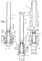
- the cream siphon shown in FIG. 1 and identified by the reference number 10 consists of the cream receptacle 11 made of metal, in particular light metal, the screw-on headpiece 12 made of plastic, which closes the interior of the container 11, a filling valve 13 for connecting the cream pressure capsule, not shown. 18 with a protective cap and 14 with a dispensing valve, on whose hollow piston 15 the dispensing nozzle 16 is seated. There is also a safety valve 17.
- the cream is poured into the interior of the cream receptacle 11 when the head piece is unscrewed. As soon as this has taken place, the container opening is closed with the head piece 12. Now the cream pressure capsule is placed in the capsule holder in a known manner and screwed together with this onto the filling valve 13. A piercing pin in the filling valve 13 pierces the piercing surface of the cream pressure capsule during the screwing process, so that the nitrogen oxide which is in the cream pressure capsule can reach the interior of the container 11 via the filling valve 13. The cream is foamed during the filling process and is under pressure. The filling valve 13 is closed by the protective cap 18 when the cream siphon 10 is not in use.
- the opening and closing of the dispensing valve 14 is carried out by an actuating lever 47 which is held in its closed position by a spring 48.
- the hollow piston 15 of the dispensing valve 14 is slidably received in a bearing bore 20 in the head piece 12 with the interposition of a seal 49.
- the seal 49 is fastened to the foot piece 21 of the hollow piston 15 in a groove 23 and lies with a partial area against the underside 22 of the head piece 12.
- the hollow piston 12 When the operating lever 47 is depressed, the hollow piston 12 is moved into the interior of the cream receptacle 11, so that the foamed cream can pass through the openings 50 and the channel 51 of the hollow piston 15 to the dispensing nozzle 16.
- the actuating lever 47 is connected via a screw nut 52 to the socket 27 of the hollow piston 15, as can be seen in FIG. 3 of the drawing.
- One of the screw nuts 52 formed on the socket 53 carries the dispensing spout 16.
- the dispensing valve 14 has an inner cavity 29 which is divided into chambers 30, 31 of different sizes and which receives the safety valve 17.
- the free end 35 of the safety valve stem 33 is equipped with a groove-like recess 36 in which a seal 37 is seated, which is in operative connection with the walls 32 of the chamber 30.
- the valve spring 38 which loads the valve head 39 of the safety piston 34, is mounted in the second chamber 31.
- the opening 40 of the chamber 31 is sealed by a screw bushing 41.
- a valve opening 42 is let into the screw bushing 41 and is blocked off by the valve head 39 via the seal 37.
- the safety valve 17 opens in that the valve head 39 opens the valve opening 42 because the force of the valve spring 38 is no longer sufficient to hold the valve head 39 in its locked position.
- the foamed cream which is under the excess pressure, can now emerge from the valve opening 42 and escape through the dispensing nozzle 16 via the chambers 31, 30, via the valve opening 20 and the interior 28 of the channel 51.
- the opening 44 of the cream receptacle 11 is equipped with a seal 45 made of rubber or plastic, which projects with a collar 46 into the interior of the cream receptacle 11.
- FIG. 4 shows a further embodiment of a dispensing valve, of which only the metering pin 19 is shown enlarged.
- the metering pin is designed as a hollow body.
- the free end 35 of the valve stem 33 is designed as a truncated cone to facilitate the installation of the safety valve 17.
- the other components of the safety valve have not been changed, so that the same reference numerals are used for this.
- the metering pin 19 of the dispensing valve 14 shown in FIG. 5 differs from that according to FIG. 4 essentially in that the screw bushing 41 is missing.
- the clamping action of the seal 37 on the walls 32 of the chamber 30 is sufficient to hold the safety piston 34 in the closed position.
- the safety piston 34 of the safety valve 17 is displaced so far inward that the seal 37 reaches the upper channel 51, the cross section of which is larger than that of the chamber 30.
- FIG. 6 A further embodiment of a dispensing valve is shown in FIG. 6. In this embodiment, in contrast to that according to FIG. 5, there are open outlets to the atmosphere.
- the illustrated embodiments are only examples of realizations of the invention. This is not limited to this. There are still various changes and training options.
- the hollow pistons 15 and the dosing pins 19 could have other shapes.
- the dispensing and safety valve can also be used for whipped cream devices, cream makers, cream blowers and similar devices.
Landscapes
- Engineering & Computer Science (AREA)
- General Engineering & Computer Science (AREA)
- Mechanical Engineering (AREA)
- Closures For Containers (AREA)
- Containers And Packaging Bodies Having A Special Means To Remove Contents (AREA)
- Feeding And Controlling Fuel (AREA)
Claims (3)
Priority Applications (1)
| Application Number | Priority Date | Filing Date | Title |
|---|---|---|---|
| AT85101661T ATE38819T1 (de) | 1984-05-26 | 1985-02-15 | Ausgabe- und sicherheitsventil fuer einen sahnesiphon o.dgl. |
Applications Claiming Priority (2)
| Application Number | Priority Date | Filing Date | Title |
|---|---|---|---|
| DE3419736A DE3419736C2 (de) | 1984-05-26 | 1984-05-26 | Ausgabe- und Sicherheitsventil für einen Sahnesiphon |
| DE3419736 | 1984-05-26 |
Publications (2)
| Publication Number | Publication Date |
|---|---|
| EP0163007A1 EP0163007A1 (fr) | 1985-12-04 |
| EP0163007B1 true EP0163007B1 (fr) | 1988-11-23 |
Family
ID=6236953
Family Applications (1)
| Application Number | Title | Priority Date | Filing Date |
|---|---|---|---|
| EP85101661A Expired EP0163007B1 (fr) | 1984-05-26 | 1985-02-15 | Soupape de distribution et de sûreté pour un siphon pour crème, ou similaire |
Country Status (5)
| Country | Link |
|---|---|
| US (1) | US4669639A (fr) |
| EP (1) | EP0163007B1 (fr) |
| AT (1) | ATE38819T1 (fr) |
| AU (1) | AU4090285A (fr) |
| DE (1) | DE3419736C2 (fr) |
Families Citing this family (21)
| Publication number | Priority date | Publication date | Assignee | Title |
|---|---|---|---|---|
| AU593032B2 (en) * | 1985-10-16 | 1990-02-01 | Rocep Lusol Holdings Limited | Aerosol valve actuator |
| DE3933360A1 (de) * | 1989-10-06 | 1991-04-18 | Stabilus Gmbh | Ausloesestift fuer ein stufenlos blockierbares hubaggregat, mit integriertem ueberdruckventil |
| DE4005529A1 (de) * | 1990-02-22 | 1991-08-29 | Pfeiffer Erich Gmbh & Co Kg | Austragkopf fuer medien |
| FR2663911B1 (fr) * | 1990-06-27 | 1994-01-28 | Oreal | Valve pour bidon aerosol, et bidon aerosol equipe d'une telle valve. |
| DE19834066C2 (de) * | 1998-07-29 | 2002-12-05 | Juengel & Severin Inh K H Moec | Sahneapparat |
| GB9930773D0 (en) * | 1999-12-30 | 2000-02-16 | Rocep Lusol Holdings | Dispensing apparatus |
| AT411171B (de) * | 2001-11-06 | 2003-10-27 | Isi Gmbh | Behälter zum erzeugen und aufbewahren von emulgierbaren lebensmitteln |
| HU227136B1 (en) * | 2002-12-12 | 2010-08-30 | Liss Patrongyarto | Siphon head for whipped cream siphon |
| PL2218655T3 (pl) | 2006-09-11 | 2013-03-29 | Friesland Brands Bv | Pojemnik z aerozolem |
| FR2927245B1 (fr) * | 2008-02-07 | 2010-05-14 | Mastrad | Appareil de cuisine du genre siphon a creme chantilly avec support de rangement |
| US20110079617A1 (en) * | 2009-10-01 | 2011-04-07 | Quarles Kenneth Wendel | Actuation device for a spray can |
| EP2487120A1 (fr) * | 2011-02-10 | 2012-08-15 | Altachem N.V. | Fourniture de soupape d'aérosol pour conteneur pressurisé, son adaptateur de fourniture, et ensemble de conteneur pressurisé avec un adaptateur |
| US9132955B2 (en) * | 2013-10-23 | 2015-09-15 | The Procter & Gamble Company | Compressible valve for a pressurized container |
| EP3148922B1 (fr) | 2014-05-24 | 2020-02-19 | Growlerwerks, Inc. | Distributeur de boissons et ensemble bouchon régulateur de pression variable |
| CA2982166A1 (fr) | 2015-04-08 | 2016-10-13 | Bunn-O-Matic Corporation | Systeme, procede et appareil d'infusion a froid |
| USD958657S1 (en) * | 2018-03-05 | 2022-07-26 | Clayton Corporation | Dispensing gun for dispensing flowable product from a pressurized can |
| CN111561591B (zh) * | 2020-03-31 | 2022-03-11 | 浙江杭惠阀门有限公司 | 一种组合式安全阀 |
| AT17447U1 (de) * | 2021-01-21 | 2022-04-15 | Isi Gmbh | Vorrichtung zum erzeugen, aufbewahren und ausgeben von cremeförmigen, emulgierbaren fluiden |
| CA219201S (en) * | 2022-08-04 | 2024-02-09 | Isi Gmbh | Replaceable bottle cover |
| CA219200S (en) * | 2022-08-04 | 2024-02-21 | Isi Gmbh | Replaceable bottle cover |
| CA219204S (en) * | 2022-08-04 | 2024-02-09 | Isi Gmbh | Replaceable bottle cover |
Citations (1)
| Publication number | Priority date | Publication date | Assignee | Title |
|---|---|---|---|---|
| DE2810996C2 (de) * | 1977-03-31 | 1982-05-13 | Giuliano Milano Massarani | Abgabeventil für aufgeschlagene Sahne |
Family Cites Families (13)
| Publication number | Priority date | Publication date | Assignee | Title |
|---|---|---|---|---|
| US2051100A (en) * | 1934-03-21 | 1936-08-18 | Nat Pressure Cooker Co | Safety valve |
| US2612293A (en) * | 1949-01-21 | 1952-09-30 | Michel Daniel | Container closure member having a dispensing valve therein |
| US2909192A (en) * | 1954-04-22 | 1959-10-20 | Bendix Aviat Corp | Check valve |
| US3081919A (en) * | 1959-04-03 | 1963-03-19 | Gulf Research Development Co | Combination dispensing and excess pressure relief valve |
| US3197144A (en) * | 1959-09-28 | 1965-07-27 | Knapp Monarch Co | Dispensing apparatus for ebullient liquids |
| US3267959A (en) * | 1963-09-25 | 1966-08-23 | Donald W Barlow | Anti-fouling anti-syphoning valve |
| US3272404A (en) * | 1964-11-10 | 1966-09-13 | Robirds | Fluid dispenser |
| US3520368A (en) * | 1968-03-28 | 1970-07-14 | Du Pont | Automatic fire alarm and extinguisher apparatus |
| US3578788A (en) * | 1968-11-13 | 1971-05-18 | Union Carbide Corp | Gas liquid withdrawal valve |
| US3666148A (en) * | 1969-10-13 | 1972-05-30 | Gillette Co | Aerosol valve with safety relief device |
| DE2419613C2 (de) * | 1974-04-24 | 1983-05-19 | Robert Bosch Gmbh, 7000 Stuttgart | Steuerventil für hydraulische Anlagen |
| US3976221A (en) * | 1974-06-28 | 1976-08-24 | Gmf Inc. | Carbonator and dispenser for carbonated liquid or the like |
| DE2648333C2 (de) * | 1976-10-26 | 1985-02-21 | Suevia Haiges GmbH & Co, 7125 Kirchheim | Tränkebeckenventil |
-
1984
- 1984-05-26 DE DE3419736A patent/DE3419736C2/de not_active Expired
-
1985
- 1985-02-15 AT AT85101661T patent/ATE38819T1/de not_active IP Right Cessation
- 1985-02-15 EP EP85101661A patent/EP0163007B1/fr not_active Expired
- 1985-04-04 AU AU40902/85A patent/AU4090285A/en not_active Abandoned
- 1985-05-16 US US06/734,904 patent/US4669639A/en not_active Expired - Fee Related
Patent Citations (1)
| Publication number | Priority date | Publication date | Assignee | Title |
|---|---|---|---|---|
| DE2810996C2 (de) * | 1977-03-31 | 1982-05-13 | Giuliano Milano Massarani | Abgabeventil für aufgeschlagene Sahne |
Also Published As
| Publication number | Publication date |
|---|---|
| US4669639A (en) | 1987-06-02 |
| DE3419736C2 (de) | 1986-11-06 |
| EP0163007A1 (fr) | 1985-12-04 |
| ATE38819T1 (de) | 1988-12-15 |
| DE3419736A1 (de) | 1985-11-28 |
| AU4090285A (en) | 1985-11-28 |
Similar Documents
| Publication | Publication Date | Title |
|---|---|---|
| EP0163007B1 (fr) | Soupape de distribution et de sûreté pour un siphon pour crème, ou similaire | |
| DE2531919B2 (de) | Betätigungsvorrichtung für ein Aerosolventil | |
| DE2101445A1 (de) | Vorrichtung fur die Abgabe von Flussig keiten aus einem Behalter | |
| DE2362422A1 (de) | Selbsttaetig absperrende zapfpistole | |
| DE2135346A1 (de) | Austeilerventil zur Abgabe zwei ver schiedener Flüssigkeiten aus einem Aerosolbehälter | |
| EP0240969A2 (fr) | Appareil de remplissage de pneus, notamment pour remplir des pneus de bicyclette | |
| DE2215605A1 (de) | Austeiler ventil für Aerosolbehälter | |
| EP0393234B1 (fr) | Soupape pour bouteilles de gaz | |
| EP1378484A1 (fr) | Système de liaison pour une installation de carbonation | |
| DE60307407T2 (de) | Siphonkopf | |
| DE1750241A1 (de) | Drucknachfuellventil | |
| DE1948492A1 (de) | Gasabfuellbehaelter fuer das Fuellen von Gasfeuerzeugen | |
| EP1176347B1 (fr) | Dispositif de commande manuelle pour actionner des soupapes | |
| EP0054717A1 (fr) | Dispositif pour prise de gaz | |
| DE3306626C2 (fr) | ||
| DE102015014008A1 (de) | Zapfhahn zum Ausschank von Getränken | |
| DE3517364A1 (de) | Verschluss- und fuellvorrichtung fuer druckmittelbehaelter | |
| DE1027147B (de) | Dosierventil | |
| DE3337197C2 (fr) | ||
| WO1992022448A1 (fr) | Appareil de gonflage de pneus | |
| DE19834066C2 (de) | Sahneapparat | |
| DE2931501A1 (de) | Absperrventil fuer druckgasbehaelter u.dgl., insbesondere fuer handfeuerloescher | |
| EP0245319B1 (fr) | Dispositif de distribution de matieres visqueuses telles que des liquides, cremes, pates ou similaires contenus dans un recipient de stockage | |
| AT212177B (de) | Ventilanordnung zur Ausgabe einer unter Druck stehenden Flüssigkeit | |
| DE4324220C2 (de) | Reifenfüllgerät |
Legal Events
| Date | Code | Title | Description |
|---|---|---|---|
| PUAI | Public reference made under article 153(3) epc to a published international application that has entered the european phase |
Free format text: ORIGINAL CODE: 0009012 |
|
| AK | Designated contracting states |
Designated state(s): AT BE CH DE FR GB IT LI LU NL |
|
| 17P | Request for examination filed |
Effective date: 19860526 |
|
| 17Q | First examination report despatched |
Effective date: 19861031 |
|
| ITF | It: translation for a ep patent filed |
Owner name: CALVANI SALVI E VERONELLI S.R.L. |
|
| GRAA | (expected) grant |
Free format text: ORIGINAL CODE: 0009210 |
|
| AK | Designated contracting states |
Kind code of ref document: B1 Designated state(s): AT BE CH FR GB IT LI LU NL |
|
| REF | Corresponds to: |
Ref document number: 38819 Country of ref document: AT Date of ref document: 19881215 Kind code of ref document: T |
|
| GBT | Gb: translation of ep patent filed (gb section 77(6)(a)/1977) | ||
| ET | Fr: translation filed | ||
| PG25 | Lapsed in a contracting state [announced via postgrant information from national office to epo] |
Ref country code: LU Free format text: LAPSE BECAUSE OF NON-PAYMENT OF DUE FEES Effective date: 19890228 |
|
| PLBE | No opposition filed within time limit |
Free format text: ORIGINAL CODE: 0009261 |
|
| STAA | Information on the status of an ep patent application or granted ep patent |
Free format text: STATUS: NO OPPOSITION FILED WITHIN TIME LIMIT |
|
| 26N | No opposition filed | ||
| PGFP | Annual fee paid to national office [announced via postgrant information from national office to epo] |
Ref country code: LU Payment date: 19900207 Year of fee payment: 6 |
|
| PGFP | Annual fee paid to national office [announced via postgrant information from national office to epo] |
Ref country code: CH Payment date: 19900212 Year of fee payment: 6 |
|
| PGFP | Annual fee paid to national office [announced via postgrant information from national office to epo] |
Ref country code: FR Payment date: 19900214 Year of fee payment: 6 |
|
| PGFP | Annual fee paid to national office [announced via postgrant information from national office to epo] |
Ref country code: BE Payment date: 19900221 Year of fee payment: 6 |
|
| PGFP | Annual fee paid to national office [announced via postgrant information from national office to epo] |
Ref country code: AT Payment date: 19900226 Year of fee payment: 6 |
|
| ITTA | It: last paid annual fee | ||
| PGFP | Annual fee paid to national office [announced via postgrant information from national office to epo] |
Ref country code: NL Payment date: 19900228 Year of fee payment: 6 Ref country code: GB Payment date: 19900228 Year of fee payment: 6 |
|
| PG25 | Lapsed in a contracting state [announced via postgrant information from national office to epo] |
Ref country code: GB Effective date: 19910215 Ref country code: AT Effective date: 19910215 |
|
| PG25 | Lapsed in a contracting state [announced via postgrant information from national office to epo] |
Ref country code: LI Effective date: 19910228 Ref country code: CH Effective date: 19910228 Ref country code: BE Effective date: 19910228 |
|
| PG25 | Lapsed in a contracting state [announced via postgrant information from national office to epo] |
Ref country code: NL Effective date: 19910901 |
|
| GBPC | Gb: european patent ceased through non-payment of renewal fee | ||
| NLV4 | Nl: lapsed or anulled due to non-payment of the annual fee | ||
| PG25 | Lapsed in a contracting state [announced via postgrant information from national office to epo] |
Ref country code: FR Effective date: 19911031 |
|
| REG | Reference to a national code |
Ref country code: CH Ref legal event code: PL |
|
| REG | Reference to a national code |
Ref country code: FR Ref legal event code: ST |