EP0163007B1 - Ausgabe- und Sicherheitsventil für einen Sahnesiphon o.dgl. - Google Patents
Ausgabe- und Sicherheitsventil für einen Sahnesiphon o.dgl. Download PDFInfo
- Publication number
- EP0163007B1 EP0163007B1 EP85101661A EP85101661A EP0163007B1 EP 0163007 B1 EP0163007 B1 EP 0163007B1 EP 85101661 A EP85101661 A EP 85101661A EP 85101661 A EP85101661 A EP 85101661A EP 0163007 B1 EP0163007 B1 EP 0163007B1
- Authority
- EP
- European Patent Office
- Prior art keywords
- valve
- safety valve
- cream
- container
- dispensing
- Prior art date
- Legal status (The legal status is an assumption and is not a legal conclusion. Google has not performed a legal analysis and makes no representation as to the accuracy of the status listed.)
- Expired
Links
- 239000006071 cream Substances 0.000 title claims abstract description 32
- 238000012856 packing Methods 0.000 claims 1
- 239000002775 capsule Substances 0.000 description 5
- MWUXSHHQAYIFBG-UHFFFAOYSA-N Nitric oxide Chemical compound O=[N] MWUXSHHQAYIFBG-UHFFFAOYSA-N 0.000 description 3
- 230000009471 action Effects 0.000 description 2
- 238000004519 manufacturing process Methods 0.000 description 2
- 239000002184 metal Substances 0.000 description 2
- 230000001681 protective effect Effects 0.000 description 2
- 239000008256 whipped cream Substances 0.000 description 2
- 230000008901 benefit Effects 0.000 description 1
- POIUWJQBRNEFGX-XAMSXPGMSA-N cathelicidin Chemical compound C([C@@H](C(=O)N[C@@H](CCCNC(N)=N)C(=O)N[C@@H](CCCCN)C(=O)N[C@@H](CO)C(=O)N[C@@H](CCCCN)C(=O)N[C@@H](CCC(O)=O)C(=O)N[C@@H](CCCCN)C(=O)N[C@@H]([C@@H](C)CC)C(=O)NCC(=O)N[C@@H](CCCCN)C(=O)N[C@@H](CCC(O)=O)C(=O)N[C@@H](CC=1C=CC=CC=1)C(=O)N[C@@H](CCCCN)C(=O)N[C@@H](CCCNC(N)=N)C(=O)N[C@@H]([C@@H](C)CC)C(=O)N[C@@H](C(C)C)C(=O)N[C@@H](CCC(N)=O)C(=O)N[C@@H](CCCNC(N)=N)C(=O)N[C@@H]([C@@H](C)CC)C(=O)N[C@@H](CCCCN)C(=O)N[C@@H](CC(O)=O)C(=O)N[C@@H](CC=1C=CC=CC=1)C(=O)N[C@@H](CC(C)C)C(=O)N[C@@H](CCCNC(N)=N)C(=O)N[C@@H](CC(N)=O)C(=O)N[C@@H](CC(C)C)C(=O)N[C@@H](C(C)C)C(=O)N1[C@@H](CCC1)C(=O)N[C@@H](CCCNC(N)=N)C(=O)N[C@@H]([C@@H](C)O)C(=O)N[C@@H](CCC(O)=O)C(=O)N[C@@H](CO)C(O)=O)NC(=O)[C@H](CC=1C=CC=CC=1)NC(=O)[C@H](CC(O)=O)NC(=O)CNC(=O)[C@H](CC(C)C)NC(=O)[C@@H](N)CC(C)C)C1=CC=CC=C1 POIUWJQBRNEFGX-XAMSXPGMSA-N 0.000 description 1
- 230000008859 change Effects 0.000 description 1
- 230000000994 depressogenic effect Effects 0.000 description 1
- 238000002474 experimental method Methods 0.000 description 1
- 238000005429 filling process Methods 0.000 description 1
- 239000007789 gas Substances 0.000 description 1
- 238000009434 installation Methods 0.000 description 1
- 238000000034 method Methods 0.000 description 1
- 239000000203 mixture Substances 0.000 description 1
- 230000008569 process Effects 0.000 description 1
- 230000004044 response Effects 0.000 description 1
- 238000007789 sealing Methods 0.000 description 1
Images


Classifications
-
- B—PERFORMING OPERATIONS; TRANSPORTING
- B67—OPENING, CLOSING OR CLEANING BOTTLES, JARS OR SIMILAR CONTAINERS; LIQUID HANDLING
- B67D—DISPENSING, DELIVERING OR TRANSFERRING LIQUIDS, NOT OTHERWISE PROVIDED FOR
- B67D1/00—Apparatus or devices for dispensing beverages on draught
- B67D1/04—Apparatus utilising compressed air or other gas acting directly or indirectly on beverages in storage containers
- B67D1/0456—Siphons, i.e. beverage containers under gas pressure without supply of further pressurised gas during dispensing
-
- F—MECHANICAL ENGINEERING; LIGHTING; HEATING; WEAPONS; BLASTING
- F16—ENGINEERING ELEMENTS AND UNITS; GENERAL MEASURES FOR PRODUCING AND MAINTAINING EFFECTIVE FUNCTIONING OF MACHINES OR INSTALLATIONS; THERMAL INSULATION IN GENERAL
- F16K—VALVES; TAPS; COCKS; ACTUATING-FLOATS; DEVICES FOR VENTING OR AERATING
- F16K17/00—Safety valves; Equalising valves, e.g. pressure relief valves
- F16K17/02—Safety valves; Equalising valves, e.g. pressure relief valves opening on surplus pressure on one side; closing on insufficient pressure on one side
- F16K17/168—Safety valves; Equalising valves, e.g. pressure relief valves opening on surplus pressure on one side; closing on insufficient pressure on one side combined with manually-controlled valves, e.g. a valve combined with a safety valve
Definitions
- the invention relates to an output and safety valve for a cream siphon, which is controllable by an actuating element under the influence of a spring and is mounted in the lid of the cream receptacle.
- a dispensing valve for whipped cream which can be actuated by means of a two-armed lever and forms a unit with the lid of a container provided with a cream dispensing nozzle.
- the container is designed to hold a mixture of cream and gas under pressure.
- the lid of the container has a through hole in a region of greater thickness, which can be closed by a valve which is under the action of a spring which overcomes the pushing force acting against it as a result of the normal operating pressure prevailing inside the container.
- the dispensing valve it also functions as a safety valve.
- the spring force of the spring which loads the valve, is dimensioned so that it gives way when the internal pressure exceeds the intended limit values. This is the case, for example, if excess pressure occurs inside the container.
- Such overpressure causes an attachment element to be raised and leads to the container contents being dispensed until the operating pressure in the container is restored.
- the invention has for its object to provide an output and safety valve of the generic type, which is composed of a few individual parts and which can be retrofitted into an existing cream siphon.
- This object is achieved in by an internal, open to the container interior cavity in which a separate Sicherhei t is skolben displaceably mounted, which receives a standing with the wall of the chamber in operative connection seal on its side facing the container exterior end in a groove-like recess and the its other end has a widened head, on which one end of a valve spring is supported, the other end of which rests on the end face of the cavity wall facing the interior of the container, the wall of the cavity having outlets or extensions which are open to the atmosphere and which, when the safety valve responds come into contact with the interior of the container.
- This configuration has the advantage that the safety valve is embedded in the dispensing valve in a space-saving and protected manner. There is no structural change to the cream siphon. The safety valve inserted in the dispensing valve in no way affects the function of the dispensing valve. A good guidance of the safety piston and a safe response of the safety valve is achieved when the permissible maximum pressure is exceeded.
- the free end of the safety piston can be designed as a truncated cone. This is recommended for manufacturing reasons.
- the cavity which is open toward the interior of the container can expediently be sealed by a screw bushing, the screw bushing having a valve opening which can be shut off by the widened head of the safety piston designed as a valve disk. This design ensures that the safety piston cannot fall out of the cavity even when the cream siphon is being filled.
- the cream siphon shown in FIG. 1 and identified by the reference number 10 consists of the cream receptacle 11 made of metal, in particular light metal, the screw-on headpiece 12 made of plastic, which closes the interior of the container 11, a filling valve 13 for connecting the cream pressure capsule, not shown. 18 with a protective cap and 14 with a dispensing valve, on whose hollow piston 15 the dispensing nozzle 16 is seated. There is also a safety valve 17.
- the cream is poured into the interior of the cream receptacle 11 when the head piece is unscrewed. As soon as this has taken place, the container opening is closed with the head piece 12. Now the cream pressure capsule is placed in the capsule holder in a known manner and screwed together with this onto the filling valve 13. A piercing pin in the filling valve 13 pierces the piercing surface of the cream pressure capsule during the screwing process, so that the nitrogen oxide which is in the cream pressure capsule can reach the interior of the container 11 via the filling valve 13. The cream is foamed during the filling process and is under pressure. The filling valve 13 is closed by the protective cap 18 when the cream siphon 10 is not in use.
- the opening and closing of the dispensing valve 14 is carried out by an actuating lever 47 which is held in its closed position by a spring 48.
- the hollow piston 15 of the dispensing valve 14 is slidably received in a bearing bore 20 in the head piece 12 with the interposition of a seal 49.
- the seal 49 is fastened to the foot piece 21 of the hollow piston 15 in a groove 23 and lies with a partial area against the underside 22 of the head piece 12.
- the hollow piston 12 When the operating lever 47 is depressed, the hollow piston 12 is moved into the interior of the cream receptacle 11, so that the foamed cream can pass through the openings 50 and the channel 51 of the hollow piston 15 to the dispensing nozzle 16.
- the actuating lever 47 is connected via a screw nut 52 to the socket 27 of the hollow piston 15, as can be seen in FIG. 3 of the drawing.
- One of the screw nuts 52 formed on the socket 53 carries the dispensing spout 16.
- the dispensing valve 14 has an inner cavity 29 which is divided into chambers 30, 31 of different sizes and which receives the safety valve 17.
- the free end 35 of the safety valve stem 33 is equipped with a groove-like recess 36 in which a seal 37 is seated, which is in operative connection with the walls 32 of the chamber 30.
- the valve spring 38 which loads the valve head 39 of the safety piston 34, is mounted in the second chamber 31.
- the opening 40 of the chamber 31 is sealed by a screw bushing 41.
- a valve opening 42 is let into the screw bushing 41 and is blocked off by the valve head 39 via the seal 37.
- the safety valve 17 opens in that the valve head 39 opens the valve opening 42 because the force of the valve spring 38 is no longer sufficient to hold the valve head 39 in its locked position.
- the foamed cream which is under the excess pressure, can now emerge from the valve opening 42 and escape through the dispensing nozzle 16 via the chambers 31, 30, via the valve opening 20 and the interior 28 of the channel 51.
- the opening 44 of the cream receptacle 11 is equipped with a seal 45 made of rubber or plastic, which projects with a collar 46 into the interior of the cream receptacle 11.
- FIG. 4 shows a further embodiment of a dispensing valve, of which only the metering pin 19 is shown enlarged.
- the metering pin is designed as a hollow body.
- the free end 35 of the valve stem 33 is designed as a truncated cone to facilitate the installation of the safety valve 17.
- the other components of the safety valve have not been changed, so that the same reference numerals are used for this.
- the metering pin 19 of the dispensing valve 14 shown in FIG. 5 differs from that according to FIG. 4 essentially in that the screw bushing 41 is missing.
- the clamping action of the seal 37 on the walls 32 of the chamber 30 is sufficient to hold the safety piston 34 in the closed position.
- the safety piston 34 of the safety valve 17 is displaced so far inward that the seal 37 reaches the upper channel 51, the cross section of which is larger than that of the chamber 30.
- FIG. 6 A further embodiment of a dispensing valve is shown in FIG. 6. In this embodiment, in contrast to that according to FIG. 5, there are open outlets to the atmosphere.
- the illustrated embodiments are only examples of realizations of the invention. This is not limited to this. There are still various changes and training options.
- the hollow pistons 15 and the dosing pins 19 could have other shapes.
- the dispensing and safety valve can also be used for whipped cream devices, cream makers, cream blowers and similar devices.
Description
- Die Erfindung bezieht sich auf ein Ausgabe-und Sicherheitsventil für einen Sahnesyphon, das durch ein unter Einfluß einer Feder stehendem Betätigungselement steuerbar und in dem Deckel des Sahneaufnahmebehälters gelagert ist.
- Es ist bekannt, diese Geräte mit einem Sicherheitsventil auszurüsten, das sich beim Überschreiten eines vorbestimmten Höchstdruckes selbsttätig öffnet. Die Verwendung zweier getrennter Ventile, wobei das eine zur Ausgabe und das andere zur Sicherheit dient, erhöht einmal den Herstellungsaufwand beträchtlich und bietet zum anderen wegen der kleinen Flächen des Verschlußdeckels, in dem die Ventile untergebracht werden müssen, aus konstruktiven Gründen Schwierigkeiten.
- Um hier Abhilfe zu schaffen, hat man auch schon versucht, das Ausgabeventil mit einem eingebauten Sicherheitsventil auszurüsten. Diese Möglichkeit bietet sich aber nur dann, wenn das Ausgabeventil mit Hilfe eines Betätigungshebels in eine Offen- oder Schließlage überführt werden kann. Für die übrigen Ausführungsformen, bei denen das Ausgabeventil durch Hin- und Herbewegen eines Dosierstiftes gesteuert wird, war ein besonderes Sicherheitsventil erforderlich.
- Durch die DE-PS-2 810 996 ist ein Abgabeventil für aufgeschlagene Sahne bekanntgeworden, das mittels eines zweiarmigen Hebels betätigbar ist und mit dem Deckel eines mit einer Sahneabgabetülle versehenen Behälters eine Einheit bildet. Der Behälter ist zur Aufnahme einer Mischung aus Sahne und unter Druck stehendem Gas bestimmt. Der Deckel des Behälters hat in einem Bereich größerer Dicke ein durchgehendes Loch, das durch ein Ventil abschließbar ist, welches unter der Einwirkung einer Feder steht, die die ihr entgegenwirkende Schubkraft infolge des im Inneren des Behälters herrschenden normalen Betriebsdruckes dabei überwindet. Bei dieser vorbekannten Ausführungsform des Ausgabeventils hat dieses zugleich die Funktion eines Sicherheitsventils. Die Federkraft der Feder, welche das Ventil belastet, ist dabei so bemessen, daß sie dann nachgibt, wenn der Innendruck die vorgesehenen Grenzwerte überschreitet. Dies ist beispielsweise dann der Fall, wenn im Inneren des Behälters Überdruck auftritt. Ein solcher Überdruck bewirkt das Anheben eines Ansatzorganes und führt zu einer Abgabe des Behälterinhaltes so lange, bis der Betriebsdruck im Behälter wieder hergestellt ist.
- Der Erfindung liegt die Aufgabe zugrunde, ein Ausgabe- und Sicherheitsventil der gattungsgemäßen Art zu schaffen, welches sich aus wenigen Einzelteilen zusammensetzt und welches sich nachträglich in einen bereits vorhandenen Sahnesyphon einsetzen läßt.
- Gelöst wird diese Aufgabe durch einen inneren, zum Behälterinneren hin offenen Hohlraum, in dem ein separater Sicherheitskolben verschieblich gelagert ist, welcher an seinem zum Behälteräußeren weisenden Ende in einer rinnenartigen Vertiefung eine mit der Wand der Kammer in Wirkverbindung stehende Dichtung aufnimmt und der an seinem anderen Ende einen verbreiterten Kopf aufweist, an dem sich das eine Ende einer Ventilfeder abstützt, deren anderes Ende an der zum Behälterinneren weisenden Stirnfläche der Hohlraumwand anliegt, wobei die Wand des Hohlraumes zur Atmosphäre hin offene Auslässe oder Erweiterungen aufweist, die beim Ansprechen des Sicherheitsventils mit dem Behälterinnenraum in Verbindung kommen. Bei dieser Ausbildung ergibt sich der Vorteil, daß das Sicherheitsventil raumsparend und geschützt in dem Ausgabeventil eingebettet ist. Eine bauliche Veränderung des Sahnesyphons entfällt. Das in das Ausgabeventil eingesetzte Sicherheitsventil beeinträchtigt in keiner Weise die Funktion des Ausgabeventils. Es ist eine gute Führung des Sicherheitskolbens und auch ein sicheres Ansprechen des Sicherheitsventils beim Überschreiten des zulässigen Höchstdruckes erzielt.
- Nach einem weiteren Merkmal der Erfindung kann das freie Ende des Sicherheitskolbens als Kegelstumpf ausgebildet sein. Dies ist aus fertigungstechnischen Gründen empfehlenswert.
- Zweckmäßig kann der zum Behälterinneren hin offene Hohlraum durch eine Schraubbuchse abgedichtet sein, wobei die Schraubbuchse eine Ventilöffnung aufweist, die durch den als Ventilteller ausgebildeten verbreiterten Kopf des Sicherheitskolbens absperrbar ist. Durch diese Ausbildung wird sichergestellt, daß der Sicherheitskolben auch beim Füllen des Sahnesyphons nicht aus dem Hohlraum herausfallen kann.
- Auf der Zeichnung ist die Erfindung in einem Ausführungsbeispiel dargestellt. Es zeigt:
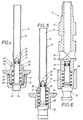
- Fig. 1 einen Sahnesyphon in Seitenansicht,
- Fig. 2 einen Schnitt durch das Kopfstück eines Sahnesyphons, bei dem das Ausgabeventil durch einen federbelasteten Betätigungshebel steuerbar ist,
- Fig. 3 einen vergrößerten Teilschnitt durch Bereiche des Kopfstückes der Ausführungsform des Sahnesyphons nach der Fig. 2 und
- Fig. 4 bis 6 vergrößerte Schnitte durch weitere Ausführungsformen eines Ausgabeventils eines Syphons mit eingesetztem Sicherheitsventil.
- Der in der Fig. 1 dargestellte und mit dem Bezugszeichen 10 gekennzeichnete Sahnesyphon besteht aus dem Sahneaufnahmebehälter 11 aus Metall, insbesondere Leichtmetall, dem aufschraubbaren Kopfstück 12 aus Kunststoff, das den Innenraum des Behälters 11 verschließt, einem Füllventil 13 zum Anschluß der nicht dargestellten Sahnedruckkapsel. Mit 18 ist eine Schutzkappe und mit 14 ein Ausgabeventil bezeichnet, auf dessen Hohlkolben 15 die Ausgabetülle 16 sitzt. Ferner ist ein Sicherheitsventil 17 vorhanden.
- Die Sahne wird bei abgeschraubtem Kopfstück in den Innenraum des Sahneaufnahmebehälters 11 eingefüllt. Sobald dies erfolgt ist, wird die Behälteröffnung mit dem Kopfstück 12 verschlossen. Nun wird in bekannter Weise die Sahnedruckkapsel in den Kapselhalter gelegt und gemeinsam mit diesem auf das Füllventil 13 geschraubt. Ein in dem Füllventil 13 sitzender Anstechstift durchsticht beim Schraubvorgang die Anstechfläche der Sahnedruckkapsel, so daß das Stickoxydul das sich in der Sahnedruckkapsel befindet, über das Füllventil 13 in den Innenraum des Behälters 11 gelangen kann. Die Sahne wird beim Einfüllvorgang aufgeschäumt und steht unter Druck. Das Füllventil 13 wird bei Nichtbenutzung des Sahnesyphons 10 durch die Schutzkappe 18 verschlossen.
- Wie aus den Fig. 2 und 3 der Zeichnung hervorgeht, erfolgt das Öffnen und Schließen des Ausgabeventils 14 durch einen Betätigungshebel 47, der durch eine Feder 48 in seiner Schließlage gehalten wird. Der Hohlkolben 15 des Ausgabeventils 14 ist in einer Lagerbohrung 20 im Kopfstück 12 unter Zwischenschalten einer Dichtung 49 verschiebbar aufgenommen. Die Dichtung 49 ist am Fußstück 21 des Hohlkolbens 15 in einer Nut 23 befestigt und legt sich mit einem Teilbereich gegen die Unterseite 22 des Kopfstückes 12.
- Beim Niederdrücken des Betätigungshebels 47 wird der Hohlkolben 12 in den Innenraum des Sahneaufnahmebehälters 11 verschoben, so daß die aufgeschäumte Sahne durch die Öffnungen 50 und den Kanal 51 des Hohlkolbens 15 zur Ausgabetülle 16 gelangen kann. Der Betätigungshebel 47 ist über eine Schraubmutter 52 mit dem Stutzen 27 des Hohlkolbens 15 verbunden, wie es die Fig. 3 der Zeichnung erkennen läßt. Eine der Schraubmutter 52 angeformter Stutzen 53 trägt die Ausgabetülle 16.
- Wie aus der Fig. 3 ersichtlich, weist das Ausgabeventil 14 einen inneren Hohlraum 29 auf, der in Kammern 30, 31 unterschiedlicher Größe unterteilt ist und der das Sicherheitsventil 17 aufnimmt.
- Das freie Ende 35 des Sicherheitsventilschaftes 33 ist mit einer rinnenartigen Vertiefung 36 ausgerüstet, in der eine Dichtung 37 sitzt, die mit den Wänden 32 der Kammer 30 in Wirkverbindung steht. In der zweiten Kammer 31 ist die Ventilfeder 38 gelagert, die den Ventilkopf 39 des Sicherheitskolbens 34 belastet. Die Öffnung 40 der Kammer 31 wird durch eine Schraubbuchse 41 abgedichtet. In der Schraubbuchse 41 ist eine Ventilöffnung 42 eingelassen, die durch den Ventilkopf 39 über die Dichtung 37 abgesperrt ist.
- Wenn im Innenraum des Sahnneaufnahmebehälters 11 der zulässige Höchstdruck überschritten wird, öffnet sich das Sicherheitsventil 17 dadurch, daß der Ventilkopf 39 die Ventilöffnung 42 freigibt, weil die Kraft der Ventilfeder 38 nicht mehr ausreicht, um den Ventilkopf 39 in seiner Sperrstellung zu halten. Die unter dem Überdruck stehende aufgeschäumte Sahne kann nunmehr aus der Ventilöffnung 42 austreten und über die Kammern 31, 30, über die Ventilöffnung 20 und den Innenraum 28 des Kanals 51 durch die Ausgabetülle 16 entweichen.
- Die Öffnung 44 des Sahneaufnahmebehälters 11 ist mit einer Dichtung 45 aus Gummi oder Kunststoff ausgerüstet, die mit einem Kragen 46 in den Innenraum des Sahneaufnahmebehälters 11 hineinragt.
- Die Fig. 4 zeigt eine weitere Ausführungsform eines Ausgabeventils, von dem lediglich der Dosierstift 19 vergrößert dargestellt ist. Der Dosierstift ist als Hohlkörper ausgebildet. Das freie Ende 35 des Ventilschaftes 33 ist als Kegelstumpf gestaltet, um den Einbau des Sicherheitsventils 17 zu erleichtern. Die übrigen Bauteile des Sicherheitsventils sind nicht geändert worden, so daß hierfur die gleichen Bezugszeichen verwendet werden.
- Der in der Fig. 5 wiedergegebene Dosierstift 19 des Ausgabeventils 14 unterscheidet sich von derjenigen nach der Fig. 4 im wesentlichen dadurch, daß die Schraubbuchse 41 fehlt. Versuche haben ergeben, daß die Klemmwirkung der Dichtung 37 an den Wänden 32 der Kammer 30 ausreicht, um den Sicherheitskolben 34 in der Schließstellung zu halten. In der Offenstellung wird der Sicherheitskolben 34 des Sicherheitsventils 17 so weit nach innen verschoben, daß die Dichtung 37 in den oberen Kanal 51 gelangt, dessen Querschnitt gegenüber demjenigen der Kammer 30 größer bemessen ist.
- Eine weitere Ausführungsform eines Ausgabeventils zeigt die Fig. 6. Bei dieser Ausführungsform sind im Gegensatz zu derjenigen nach der Fig. 5 offene Auslässe zur Atmosphäre hin vorhanden.
- Wie bereits erwähnt, sind die dargestellten Ausführungen nur beispielsweise Verwirklichungen der Erfindung. Diese ist nicht darauf beschränkt. Es sind noch mancherlei Abänderungen und Ausbildungen möglich. So könnten die Hohlkolben 15 und die Dosierstifte 19 andere Formen aufweisen. Ferner kann das Ausgabe- und Sicherheitsventil auch für Schlagsahnegeräte, Sahnebereiter, Rahmbläser und ähnliche Geräte verwendet werden.
Claims (3)
gekennzeichnet durch
einen inneren, zum Behälterinneren hin offenen Hohlraum (29), in dem ein separater Sicherheitskolben (34) verschieblich gelagert ist, welcher an seinem zum Behälteräußeren weisenden Ende (35) in einer rinnenartigen Vertiefung (36) eine mit der Wand (32) der Kammer (30) in Wirkverbindung stehende Dichtung (37) aufnimmt und der an seinem anderen Ende einen verbreiterten Kopf (39) aufweist, an dem sich das eine Ende einer Ventilfeder (38) abstützt, deren anderes Ende an der zum Behälterinneren weisenden Stirnfläche der Hohlraumwand anliegt, wobei die Wand (32) des Hohlraumes (29) zur Atmosphäre hin offene Auslässe oder Erweiterungen aufweist, die beim Ansprechen des Sicherheitsventils (17) mit dem Behälterinnenraum in Verbindung kommen.
Priority Applications (1)
| Application Number | Priority Date | Filing Date | Title |
|---|---|---|---|
| AT85101661T ATE38819T1 (de) | 1984-05-26 | 1985-02-15 | Ausgabe- und sicherheitsventil fuer einen sahnesiphon o.dgl. |
Applications Claiming Priority (2)
| Application Number | Priority Date | Filing Date | Title |
|---|---|---|---|
| DE3419736A DE3419736C2 (de) | 1984-05-26 | 1984-05-26 | Ausgabe- und Sicherheitsventil für einen Sahnesiphon |
| DE3419736 | 1984-05-26 |
Publications (2)
| Publication Number | Publication Date |
|---|---|
| EP0163007A1 EP0163007A1 (de) | 1985-12-04 |
| EP0163007B1 true EP0163007B1 (de) | 1988-11-23 |
Family
ID=6236953
Family Applications (1)
| Application Number | Title | Priority Date | Filing Date |
|---|---|---|---|
| EP85101661A Expired EP0163007B1 (de) | 1984-05-26 | 1985-02-15 | Ausgabe- und Sicherheitsventil für einen Sahnesiphon o.dgl. |
Country Status (5)
| Country | Link |
|---|---|
| US (1) | US4669639A (de) |
| EP (1) | EP0163007B1 (de) |
| AT (1) | ATE38819T1 (de) |
| AU (1) | AU4090285A (de) |
| DE (1) | DE3419736C2 (de) |
Families Citing this family (20)
| Publication number | Priority date | Publication date | Assignee | Title |
|---|---|---|---|---|
| BR8606925A (pt) * | 1985-10-16 | 1987-11-03 | Rocep Lusol Holdings | Mecanismo de comando de valvula aerossol |
| DE3933360A1 (de) * | 1989-10-06 | 1991-04-18 | Stabilus Gmbh | Ausloesestift fuer ein stufenlos blockierbares hubaggregat, mit integriertem ueberdruckventil |
| DE4005529A1 (de) * | 1990-02-22 | 1991-08-29 | Pfeiffer Erich Gmbh & Co Kg | Austragkopf fuer medien |
| FR2663911B1 (fr) * | 1990-06-27 | 1994-01-28 | Oreal | Valve pour bidon aerosol, et bidon aerosol equipe d'une telle valve. |
| DE19834066C2 (de) * | 1998-07-29 | 2002-12-05 | Juengel & Severin Inh K H Moec | Sahneapparat |
| GB9930773D0 (en) * | 1999-12-30 | 2000-02-16 | Rocep Lusol Holdings | Dispensing apparatus |
| AT411171B (de) * | 2001-11-06 | 2003-10-27 | Isi Gmbh | Behälter zum erzeugen und aufbewahren von emulgierbaren lebensmitteln |
| HU227136B1 (en) * | 2002-12-12 | 2010-08-30 | Liss Patrongyarto | Siphon head for whipped cream siphon |
| DK2295339T3 (da) | 2006-09-11 | 2012-07-02 | Friesland Brands Bv | Aerosolbeholder |
| FR2927245B1 (fr) | 2008-02-07 | 2010-05-14 | Mastrad | Appareil de cuisine du genre siphon a creme chantilly avec support de rangement |
| US20110079617A1 (en) * | 2009-10-01 | 2011-04-07 | Quarles Kenneth Wendel | Actuation device for a spray can |
| EP2487120A1 (de) * | 2011-02-10 | 2012-08-15 | Altachem N.V. | Aerosolventilspender für Druckbehälter, Spenderadapter dafür sowie Anordnung eines Druckbehälters mit einem Adapter |
| US9132955B2 (en) * | 2013-10-23 | 2015-09-15 | The Procter & Gamble Company | Compressible valve for a pressurized container |
| CA3108995C (en) | 2014-05-24 | 2022-08-23 | GrowlerWerks, INC. | Beverage dispenser and variable pressure regulator cap assembly |
| US10278533B2 (en) | 2015-04-08 | 2019-05-07 | Bunn-O-Matic Corporation | Cold brew system |
| USD958657S1 (en) * | 2018-03-05 | 2022-07-26 | Clayton Corporation | Dispensing gun for dispensing flowable product from a pressurized can |
| CN111561591B (zh) * | 2020-03-31 | 2022-03-11 | 浙江杭惠阀门有限公司 | 一种组合式安全阀 |
| AT17447U1 (de) * | 2021-01-21 | 2022-04-15 | Isi Gmbh | Vorrichtung zum erzeugen, aufbewahren und ausgeben von cremeförmigen, emulgierbaren fluiden |
| USD1025774S1 (en) * | 2022-08-04 | 2024-05-07 | Isi Gmbh | Combination replaceable head and replaceable bottle covering for a hand-operated appliance for preparing food and beverages |
| CA219200S (en) * | 2022-08-04 | 2024-02-21 | Isi Gmbh | Replaceable bottle cover |
Citations (1)
| Publication number | Priority date | Publication date | Assignee | Title |
|---|---|---|---|---|
| DE2810996C2 (de) * | 1977-03-31 | 1982-05-13 | Giuliano Milano Massarani | Abgabeventil für aufgeschlagene Sahne |
Family Cites Families (13)
| Publication number | Priority date | Publication date | Assignee | Title |
|---|---|---|---|---|
| US2051100A (en) * | 1934-03-21 | 1936-08-18 | Nat Pressure Cooker Co | Safety valve |
| US2612293A (en) * | 1949-01-21 | 1952-09-30 | Michel Daniel | Container closure member having a dispensing valve therein |
| US2909192A (en) * | 1954-04-22 | 1959-10-20 | Bendix Aviat Corp | Check valve |
| US3081919A (en) * | 1959-04-03 | 1963-03-19 | Gulf Research Development Co | Combination dispensing and excess pressure relief valve |
| US3197144A (en) * | 1959-09-28 | 1965-07-27 | Knapp Monarch Co | Dispensing apparatus for ebullient liquids |
| US3267959A (en) * | 1963-09-25 | 1966-08-23 | Donald W Barlow | Anti-fouling anti-syphoning valve |
| US3272404A (en) * | 1964-11-10 | 1966-09-13 | Robirds | Fluid dispenser |
| US3520368A (en) * | 1968-03-28 | 1970-07-14 | Du Pont | Automatic fire alarm and extinguisher apparatus |
| US3578788A (en) * | 1968-11-13 | 1971-05-18 | Union Carbide Corp | Gas liquid withdrawal valve |
| US3666148A (en) * | 1969-10-13 | 1972-05-30 | Gillette Co | Aerosol valve with safety relief device |
| DE2419613C2 (de) * | 1974-04-24 | 1983-05-19 | Robert Bosch Gmbh, 7000 Stuttgart | Steuerventil für hydraulische Anlagen |
| US3976221A (en) * | 1974-06-28 | 1976-08-24 | Gmf Inc. | Carbonator and dispenser for carbonated liquid or the like |
| DE2648333C2 (de) * | 1976-10-26 | 1985-02-21 | Suevia Haiges GmbH & Co, 7125 Kirchheim | Tränkebeckenventil |
-
1984
- 1984-05-26 DE DE3419736A patent/DE3419736C2/de not_active Expired
-
1985
- 1985-02-15 EP EP85101661A patent/EP0163007B1/de not_active Expired
- 1985-02-15 AT AT85101661T patent/ATE38819T1/de not_active IP Right Cessation
- 1985-04-04 AU AU40902/85A patent/AU4090285A/en not_active Abandoned
- 1985-05-16 US US06/734,904 patent/US4669639A/en not_active Expired - Fee Related
Patent Citations (1)
| Publication number | Priority date | Publication date | Assignee | Title |
|---|---|---|---|---|
| DE2810996C2 (de) * | 1977-03-31 | 1982-05-13 | Giuliano Milano Massarani | Abgabeventil für aufgeschlagene Sahne |
Also Published As
| Publication number | Publication date |
|---|---|
| EP0163007A1 (de) | 1985-12-04 |
| DE3419736A1 (de) | 1985-11-28 |
| AU4090285A (en) | 1985-11-28 |
| US4669639A (en) | 1987-06-02 |
| DE3419736C2 (de) | 1986-11-06 |
| ATE38819T1 (de) | 1988-12-15 |
Similar Documents
| Publication | Publication Date | Title |
|---|---|---|
| EP0163007B1 (de) | Ausgabe- und Sicherheitsventil für einen Sahnesiphon o.dgl. | |
| DE2531919B2 (de) | Betätigungsvorrichtung für ein Aerosolventil | |
| DE2101445A1 (de) | Vorrichtung fur die Abgabe von Flussig keiten aus einem Behalter | |
| DE2362422A1 (de) | Selbsttaetig absperrende zapfpistole | |
| DE2135346A1 (de) | Austeilerventil zur Abgabe zwei ver schiedener Flüssigkeiten aus einem Aerosolbehälter | |
| EP0240969A2 (de) | Reifenfüllgerät, insbesondere zum Füllen von Fahrradreifen | |
| DE2215605A1 (de) | Austeiler ventil für Aerosolbehälter | |
| EP0393234B1 (de) | Gasflaschenventil | |
| EP1378484A1 (de) | Kupplung und Kupplungseinrichtung einer Karbonisiervorrichtung | |
| DE1750241A1 (de) | Drucknachfuellventil | |
| DE1948492A1 (de) | Gasabfuellbehaelter fuer das Fuellen von Gasfeuerzeugen | |
| DE60307407T2 (de) | Siphonkopf | |
| EP1176347B1 (de) | Handbetätigungseinrichtung für Ventile | |
| EP0054717A1 (de) | Vorrichtung zur Entnahme von Gas | |
| DE3306626C2 (de) | ||
| DE102015014008A1 (de) | Zapfhahn zum Ausschank von Getränken | |
| DE3517364A1 (de) | Verschluss- und fuellvorrichtung fuer druckmittelbehaelter | |
| DE1027147B (de) | Dosierventil | |
| DE3337197C2 (de) | ||
| WO1992022448A1 (de) | Reifenfüllgerät | |
| DE19834066C2 (de) | Sahneapparat | |
| DE2931501A1 (de) | Absperrventil fuer druckgasbehaelter u.dgl., insbesondere fuer handfeuerloescher | |
| EP0245319B1 (de) | Vorrichtung zum fördern von viskosen materialien, wie flüssigkeiten, creme, pasten oder dergleichen aus einem vorratsbehälter | |
| AT212177B (de) | Ventilanordnung zur Ausgabe einer unter Druck stehenden Flüssigkeit | |
| DE4324220C2 (de) | Reifenfüllgerät |
Legal Events
| Date | Code | Title | Description |
|---|---|---|---|
| PUAI | Public reference made under article 153(3) epc to a published international application that has entered the european phase |
Free format text: ORIGINAL CODE: 0009012 |
|
| AK | Designated contracting states |
Designated state(s): AT BE CH DE FR GB IT LI LU NL |
|
| 17P | Request for examination filed |
Effective date: 19860526 |
|
| 17Q | First examination report despatched |
Effective date: 19861031 |
|
| ITF | It: translation for a ep patent filed |
Owner name: CALVANI SALVI E VERONELLI S.R.L. |
|
| GRAA | (expected) grant |
Free format text: ORIGINAL CODE: 0009210 |
|
| AK | Designated contracting states |
Kind code of ref document: B1 Designated state(s): AT BE CH FR GB IT LI LU NL |
|
| REF | Corresponds to: |
Ref document number: 38819 Country of ref document: AT Date of ref document: 19881215 Kind code of ref document: T |
|
| GBT | Gb: translation of ep patent filed (gb section 77(6)(a)/1977) | ||
| ET | Fr: translation filed | ||
| PG25 | Lapsed in a contracting state [announced via postgrant information from national office to epo] |
Ref country code: LU Free format text: LAPSE BECAUSE OF NON-PAYMENT OF DUE FEES Effective date: 19890228 |
|
| PLBE | No opposition filed within time limit |
Free format text: ORIGINAL CODE: 0009261 |
|
| STAA | Information on the status of an ep patent application or granted ep patent |
Free format text: STATUS: NO OPPOSITION FILED WITHIN TIME LIMIT |
|
| 26N | No opposition filed | ||
| PGFP | Annual fee paid to national office [announced via postgrant information from national office to epo] |
Ref country code: LU Payment date: 19900207 Year of fee payment: 6 |
|
| PGFP | Annual fee paid to national office [announced via postgrant information from national office to epo] |
Ref country code: CH Payment date: 19900212 Year of fee payment: 6 |
|
| PGFP | Annual fee paid to national office [announced via postgrant information from national office to epo] |
Ref country code: FR Payment date: 19900214 Year of fee payment: 6 |
|
| PGFP | Annual fee paid to national office [announced via postgrant information from national office to epo] |
Ref country code: BE Payment date: 19900221 Year of fee payment: 6 |
|
| PGFP | Annual fee paid to national office [announced via postgrant information from national office to epo] |
Ref country code: AT Payment date: 19900226 Year of fee payment: 6 |
|
| ITTA | It: last paid annual fee | ||
| PGFP | Annual fee paid to national office [announced via postgrant information from national office to epo] |
Ref country code: NL Payment date: 19900228 Year of fee payment: 6 Ref country code: GB Payment date: 19900228 Year of fee payment: 6 |
|
| PG25 | Lapsed in a contracting state [announced via postgrant information from national office to epo] |
Ref country code: GB Effective date: 19910215 Ref country code: AT Effective date: 19910215 |
|
| PG25 | Lapsed in a contracting state [announced via postgrant information from national office to epo] |
Ref country code: LI Effective date: 19910228 Ref country code: CH Effective date: 19910228 Ref country code: BE Effective date: 19910228 |
|
| PG25 | Lapsed in a contracting state [announced via postgrant information from national office to epo] |
Ref country code: NL Effective date: 19910901 |
|
| GBPC | Gb: european patent ceased through non-payment of renewal fee | ||
| NLV4 | Nl: lapsed or anulled due to non-payment of the annual fee | ||
| PG25 | Lapsed in a contracting state [announced via postgrant information from national office to epo] |
Ref country code: FR Effective date: 19911031 |
|
| REG | Reference to a national code |
Ref country code: CH Ref legal event code: PL |
|
| REG | Reference to a national code |
Ref country code: FR Ref legal event code: ST |