EP0156108A2 - Fenster- oder Türrahmenprofil - Google Patents
Fenster- oder Türrahmenprofil Download PDFInfo
- Publication number
- EP0156108A2 EP0156108A2 EP85100615A EP85100615A EP0156108A2 EP 0156108 A2 EP0156108 A2 EP 0156108A2 EP 85100615 A EP85100615 A EP 85100615A EP 85100615 A EP85100615 A EP 85100615A EP 0156108 A2 EP0156108 A2 EP 0156108A2
- Authority
- EP
- European Patent Office
- Prior art keywords
- profile
- hollow
- wedge
- reinforcement
- hollow plastic
- Prior art date
- Legal status (The legal status is an assumption and is not a legal conclusion. Google has not performed a legal analysis and makes no representation as to the accuracy of the status listed.)
- Granted
Links
Images

Classifications
-
- E—FIXED CONSTRUCTIONS
- E06—DOORS, WINDOWS, SHUTTERS, OR ROLLER BLINDS IN GENERAL; LADDERS
- E06B—FIXED OR MOVABLE CLOSURES FOR OPENINGS IN BUILDINGS, VEHICLES, FENCES OR LIKE ENCLOSURES IN GENERAL, e.g. DOORS, WINDOWS, BLINDS, GATES
- E06B3/00—Window sashes, door leaves, or like elements for closing wall or like openings; Layout of fixed or moving closures, e.g. windows in wall or like openings; Features of rigidly-mounted outer frames relating to the mounting of wing frames
- E06B3/04—Wing frames not characterised by the manner of movement
- E06B3/06—Single frames
- E06B3/08—Constructions depending on the use of specified materials
- E06B3/20—Constructions depending on the use of specified materials of plastics
- E06B3/22—Hollow frames
- E06B3/221—Hollow frames with the frame member having local reinforcements in some parts of its cross-section or with a filled cavity
- E06B3/222—Hollow frames with the frame member having local reinforcements in some parts of its cross-section or with a filled cavity with internal prefabricated reinforcing section members inserted after manufacturing of the hollow frame
- E06B2003/225—Means for stabilising the insert
Definitions
- the invention relates to a window or door frame profile, consisting of a hollow plastic profile with an inserted reinforcing profile, in particular made of metal, the reinforcing profile being arranged in the hollow plastic profile with a certain preload and by fastening elements, e.g. screws screwed in from the outside are additionally fixed in the hollow plastic profile.
- Such a window or door frame profile is known from European patent application 77 412.
- the reinforcement profile made of thin-walled metal has been provided with relatively deep, longitudinally extending beads, which should give the reinforcement profile a certain elasticity perpendicular to the longitudinal axis in order to obtain a good bond between the reinforcement profile and the hollow plastic profile .
- the wall thickness of the reinforcement profile for steel must be in the range of 1.5 - 2 mm, this desired elasticity or spring action perpendicular to the longitudinal axis of the reinforcement profile can only be achieved by very high machine, material and force expenditure. There is with these window and door frame profiles.
- the extent of the preload with which the plastic hollow profile is to enclose the reinforcement profile here cannot be predetermined. In unfavorable cases, it can happen when the reinforcing profile is pushed into the hollow plastic profile that the front edges of the reinforcing profile scrape an inadmissible amount of material from the adjacent walls of the hollow plastic profile.
- the invention is therefore based on the object to provide a window or door frame profile made of plastic, in which a reinforcement profile - regardless of the dimensional fluctuations of its receiving space - inserted extremely easily and then by controlled fastening in positive engagement with can be brought to the hollow plastic profile, on the one hand to achieve a perfect bond between these parts and on the other hand to avoid deformation of the hollow plastic profile by the reinforcing profile.
- such a reinforcement profile can always be simple, i.e. with sufficient lateral play, can be inserted into its associated cavity and then by a controlled fastening, e.g. Tighten the screws (using a torque screwdriver) to create the required bond between the reinforcement profile and the hollow plastic profile.
- the prestressing force with which the reinforcing profile is pressed against the adjacent wedge-shaped walls of the hollow plastic profile can thus be determined beforehand, so that deformations of the hollow plastic profile can be reliably avoided.
- the stability of a reinforced plastic hollow profile according to the invention is improved in and perpendicular to the plane of the frame which is made from such profiles.
- the embodiment of the invention according to claim 2 has the advantage that the fastening elements, e.g. Screws for producing the positive connection or the composite effect between the reinforcement profile and the hollow plastic profile on its concealed side, i.e. not visible side can be arranged.
- the fastening elements e.g. Screws for producing the positive connection or the composite effect between the reinforcement profile and the hollow plastic profile on its concealed side, i.e. not visible side
- the further embodiment of the invention according to claim 3 shows that the invention can be realized advantageously either with closed or also cheaper, laterally open reinforcement profiles in the longitudinal direction.
- wedges can also be used instead of screws which drive the end face between the reinforcement and hollow plastic profile to produce the positive connection between these parts.
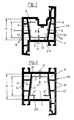
- the plastic hollow profiles 1 A - 1 F shown in section in the figures are examples of window frame profiles, but door frame profiles can also replace them, in each case for cane and casement frames.
- all of these hollow plastic profiles require the installation of a preferably metallic reinforcing profile 2 A to 2 F, which is to be brought into positive engagement with the respective hollow plastic profile in order to achieve the required bonding effect.
- the reinforcement profile 2 A is made of a galvanized sheet steel strip e.g. Roll-formed open-sided profile with a wedge-shaped cross-section, which has two longitudinal walls 3 and 4, which are connected to one another by a longitudinal wall 5.
- the free edge of the longitudinal wall 3 is bent inwards to form a flange 6.
- the flange 6 extends parallel to the longitudinal wall 5.
- the two longitudinal walls 3, 4 are arranged inclined outwards with respect to the longitudinal wall 5 connecting them or to the horizontal.
- the cavity 7 of the hollow plastic profile 1 A receiving the reinforcing profile 2A has two mutually opposite walls 8, 9, which are arranged inclined according to the longitudinal walls 3, 4 of the reinforcing profile 2A or run parallel to these.
- the wedge-shaped cross section of the reinforcement profile 2 A is therefore adapted to the clear wedge-shaped cross section of the cavity 7.
- the height h of the reinforcement profile 2A is smaller than the height of the cavity 7, so that the reinforcement profile 2A through one of the open end faces of the cavity 7 is very simple, i.e. with lateral play to all the walls 7 delimiting the cavity can be inserted therein.
- the exemplary embodiment according to FIG. 2 differs from that according to FIG. 1 essentially in that the cavity 7 for receiving the reinforcing profile 2 B has no inwardly projecting projection, so that the reinforcing profile 2 B is symmetrical with two inwardly or counter-directed flanges 6 'can be trained. Otherwise, the same parts are identified by the same reference numerals as in FIG. 1, and here too the height h of the reinforcement profile 2 B in the wedge engagement direction A is smaller than the height H of the cavity 7. These conditions also apply to the exemplary embodiments according to FIGS Figures 3 - 6.
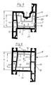
- the reinforcement profile 2 C consists of a closed, ie tubular profile with only one with respect to its longitudinal wall 5 outward sloping longitudinal wall. 3.
- the cavity 7 of the plastic hollow profile 1 C is bounded by the wall 8, which is arranged parallel to the longitudinal wall 3 of the reinforcement profile 2 C, with respect to the oblique longitudinal wall 3 of the reinforcement profile 2 C.
- the longitudinal wall 4 'of the reinforcing profile 2 C interacts with the impacting inside of the outer wall 13 of the hollow plastic profile 1 C. In this case too, when tightening the screws 11 . the reinforcement profile 2 C. pulled against the wall 10 and brought with its longitudinal walls 3, 4 1 in positive engagement with the adjacent walls 8, 13.
- the reinforcement profile 2D in the exemplary embodiment according to FIG. 4 likewise consists of a closed, ie. tubular profile with only one longitudinal wall 3 which is inclined outwards with respect to the longitudinal wall 5, while the opposite longitudinal wall 4 'encloses a right angle with the longitudinal wall 5 and the longitudinal wall 18 opposite this.
- the cavity 7 of the plastic hollow profile 1 D is laterally delimited by the oblique wall 8 'arranged parallel to the longitudinal wall 3 of the reinforcement profile 2 D and by the wall 9' arranged parallel to the longitudinal wall 4 'of the reinforcement profile 2 D.
- FIGS. 5 and 6 essentially correspond to those of FIGS. 3 and 4; in contrast to the latter, the reinforcement profiles 2 E and 2 F are open profiles on the long side.
- a flange 19 is bent on the longitudinal wall 5 at a right angle and a flange 20 is bent off at a right angle from the part 17 of the reinforcement profile 2 E in the direction of the flange 19.
- the flanges 19, 20 are aligned with one another.
- flanges 21, 22 which are bent at right angles from its longitudinal walls 5 and 18 extend against one another and are likewise aligned with one another.
- All of the exemplary embodiments according to FIGS. 1-6 have in common that the wedge engagement direction A runs parallel to the plane of a frame produced from one of the profile types 1A to 1F.
- the reinforcement profiles 2 C to 2 F according to the embodiments in FIGS. 3 to 6 also have the advantage that they are particularly effective in improving the bending stiffness of the hollow plastic profiles 1 C-1 F perpendicular to the windows or doors made from such profiles.
Landscapes
- Engineering & Computer Science (AREA)
- Civil Engineering (AREA)
- Structural Engineering (AREA)
- Wing Frames And Configurations (AREA)
- Specific Sealing Or Ventilating Devices For Doors And Windows (AREA)
- Special Wing (AREA)
- Door And Window Frames Mounted To Openings (AREA)
Abstract
Description
- Die Erfindung bezieht sich auf ein Fenster- oder TUrrahmenprofil, bestehend aus einem Kunststoffhohlprofil mit einem eingesetzten Verstärkungsprofil, insbesondere aus Metall, wobei das Verstärkungsprofil in dem Kunststoffhohlprofil mit einer gewissen Vorspannung angeordnet ist und durch Befestigungselemente, z.B. von außen eingedrehte Schrauben im Kunststoffhohlprofil zusätzlich fixiert ist.
- Ein derartiges Fenster- oder Türrahmenprofil ist durch die europäische Patentanmeldung 77 412 bekannt geworden. Um eine verbesserte Biegesteifigkeit sowie Verwindungssteifigkeit zu erreichen, hat man hier das Verstärkungsprofil aus dünnwandigem Metall mit relativ tiefen, in Längsrichtung verlaufenden Sicken versehen, die dem Verstärkungsprofil senkrecht zur Längsachse eine gewisse Elastizität verleihen sollen, um einen guten Verbund des Verstärkungsprofils mit dem Kunststoffhohlprofil zu erhalten. Da jedoch aus statischen Gründen die Wanddicke des Verstärkungsprofils bei Stahl im Bereich von 1,5 - 2 mm liegen muß, wird diese angestrebte Elastizität bzw. Federwirkung senkrecht zur Längsachse des Verstärkungsprofils nur durch sehr hohen Maschinen-, Material- und Kraftaufwand erreicht. Es besteht bei diesen Fenster- und Türrahmenprofilen . ferner die Gefahr, daß das Verstärkungsprofil, wenn es nicht maßgenau hergestellt ist, zu einer zu großen Vor-spannung in dem Kunststoffhohlprofil führt, so daß sich letzteres unzulässig stark verformt bzw. beschädigt wird. Durch die von außen durch das Kunststoffhohlprofil hindurch in eine Längssicke dieses Verstärkungsprofils eingedrehten Schrauben wird hier zwar eine zusätzliche Fixierung des Verstärkungsprofils im Kunststoffhohlprofil erzielt, keinesfalls aber eine merkliche Verbesserung der Verbundwirkung zwischen diesen Teilen erreicht. Aufgrund der obigen erforderlichen Materialdicken für das Verstärkungsprofil bzw. infolge der vorhandenen Querschnittsverhältnisse ist nämlich eine elastische Verformung auch von relativ tiefen Längssicken beim Anziehen der Schrauben praktisch ausgeschlossen. Da ferner die Abmessungen des Hohlraums im Kunststoffhohlprofil zur Aufnahme des Verstärkungsprofils-verhältnismäßig starken Schwankungen unterliegen, ist das Ausmaß der-Vorspannung, - mit der das Kunststoffhohlprofil hier das Verstärkungsprofil umschließen soll, nicht vorbestimmbar. In ungünstigen Fällen kann es schon beim Einschieben (Ein-. schlagen) des Verstärkungsprofils in das Kunststoffhohlprofil dazu kommen, daß die Stirnkanten des Verstärkungsprofils unzulässig viel Material von den benachbarten Wandungen des Kunststoffhohlprofils abschaben.
- Der Erfindung liegt daher die Aufgabe zugrunde, ein Fenster oder Türrahmenprofil aus Kunststoff zu schaffen, in das ein Verstärkungsprofil - ungeachtet der Maßschwankungen von dessen Aufnahmeraum - äußerst einfach eingeführt und dann durch kontrolliertes Befestigen in Formschluß mit dem Kunststoffhohlprofil gebracht werden kann, um einerseits einen einwandfreien Verbund zwischen diesen Teilen zu erreichen und andererseits eine Verformung des Kunststoffhohlprofils durch das Verstärkungsprofil zu vermeiden.
- Gemäß der Erfindung wird diese Aufgabe dadurch gelöst, daß
- a) der Querschnitt des Verstärkungsprofils keilförmig ist und der das Verstärkungsprofil aufnehmende Hohlraum des Kunststoffhohlprofils einen diesem angepassten lichten keilförmigen Querschnitt aufweist,
- b) die Höhe des Verstärkungsprofils in Keil-Angriffsrichtung kleiner als diejenige des das Verstärkungsprofil aufnehmenden Hohlraums im Kunststoffhohlprofil ist und
- c) die Befestigungselemente, z.B. die Schrauben zwischen dem Kunststoffhohlprofil und dem Verstärkungsprofil in Keil-Angriffsrichtung wirksam angeordnet sind, so daß bei entsprechender Betätigung bzw. Drehung derselben das Verstärkungsprofil in Formschluß mit den benachbarten keilförmig angeordneten Wänden des Kunststoffhohlprofils bringbar ist.
- Unabhängig von den Maßschwankungen beim Kunststoffhohlprofil kann ein solches Verstärkungsprofil stets einfach, d.h. mit genügend seitlichem Spiel, in seinen zugeordneten Hohlraum eingeführt werden und dann kann durch ein kontrolliertes Befestigen, z.B. Anziehen der Schrauben (mittels Drehmomentschrauber) die erforderliche Verbundwirkung zwischen Verstärkungsprofil und Kunststoffhohlprofil hergestellt werden. Die Vorspannkraft, mit der das Verstärkungsprofil dabei gegen die benachbarten keilförmig angeordneten Wände des Kunststoffhohlprofils gedrückt wird, ist also vorher bestimmbar, so daß Verformungen des Kunststoffhohlprofils zuverlässig vermieden werden können. Die Stabilität eines erfindungsgemäß verstärkten Kunststoffhohlprofils wird in und senkrecht zur Ebene des Rahmens verbessert, der aus solchen Profilen hergestellt - ist.
- Die Ausgestaltung der Erfindung entsprechend dem Anspruch 2 bringt den Vorteil, daß die Befestigungselemente, z.B. Schrauben zur Herstellung des Formschlusses bzw. der Verbundwirkung zwischen Verstärkungsprofil und Kunststoffhohlprofil an dessen verdeckt liegender Seite, d.h. nich sichtbaren Seite angeordnet werden können.
- Die weitere Ausgestaltung der Erfindung nach Anspruch 3 zeigt, daß die Erfindung vorteilhaft entweder mit geschlossenen oder auch preiswerteren, in Längsrichtung seitlich offenen Verstärkungsprofilen verwirklicht werden kann.
- Wenn gemäß dem Anspruch 4 die mit dem keilförmigen Verstärkungsprofil in Formschluß bringbaren Wände des Kunststoffhohlprofils durch seitliche Aussteifungsrippen verstärkt sind, erhöht sich durch eine bessere Kraftverteilung die Stabilität.
- Entsprechend dem Anspruch 5 können anstelle von Schrauben auch Keile verwendet werden, die stirnseitig zwischen dem Verstärkungs- und Kunststoffhohlprofil eingetrieben den Formschluß zwischen diesen Teilen herstellen.
- Die Erfindung wird anschließend anhand der Zeichnungen von Ausführungsbeispielen erläutert. Es zeigen:
- Figuren 1 - 6 verschiedene Querschnittsansichten von Kunststoffhohlprofilen mit eingesetzten metallischen Verstärkungsprofilen, die unterschiedliche keilförmige Querschnitte aufweisen.
- Die in den Figuren im Schnitt gezeigten Kunststoffhohlprofile 1 A - 1 F sind beispielhaft Fensterrahmenprofile, an ihrer Stelle können jedoch auch TUrrahmenprofile treten und zwar jeweils für Stock- und Flügelrahmen. Alle diese Kunststoffhohlprofile erfordern zur Verbesserung ihrer Biege- und Verwindungssteifigkeit den Einbau eines vorzugsweise metallischen Verstärkungsprofils 2 A bis 2 F, welches zur Erzielung der erforderlichen Verbundwirkung in Formschluß mit dem jeweiligen Kunststoffhohlprofil zu bringen ist.
- Das Verstärkungsprofil 2 A ist ein aus einem verzinkten Stahlblechstreifen z.B. im Rollformverfahren hergestelltes längsseitig offenes Profil mit keilförmigem Querschnitt, das zwei Längswände 3 und 4 aufweist, die durch eine Längswand 5 miteinander verbunden sind. Der freie Rand der Längswand 3 ist nach innen gebogen, um einen Flansch 6 auszubilden. Der Flansch 6 erstreckt sich parällel zur Längswand 5. Die beiden Längswände 3, 4 sind in bezug auf die sie verbindende Längswand 5 bzw. auf die Horizontale nach außen geneigt angeordnet. Der das Verstärkungsprofil 2 A aufnehmende Hohlraum 7 des Kunststoffhohlprofils 1 A weist zwei einander gegenüberliegende Wände 8, 9 auf, die entsprechend den Längswänden 3, 4 des Verstärkungsprofils 2 A geneigt angeordnet sind bzw. prallel zu diesen verlaufen. Dem keilförmigen Querschnitt des Verstärkungsprofils 2 A ist demzufolge der lichte keilförmige Querschnitt des Hohlraums 7 angepasst. Die Höhe h des Verstärkungsprofils 2 A ist kleiner als die Höhe des Hohlraums 7, so daß das Verstärkungsprofil 2 A durch eine der offenen Stirnseiten des Hohlraums 7 sehr einfach, d.h. mit seitlichem Spiel zu allen den Hohlraum 7 begrenzenden Wänden in diesen eingeführt werden kann.
- Um den zwischen dem Kunststoffhohlprofil 1 A und dem Verstärkungsprofil 2 A erforderlichen Verbund zu erreichen, ist es notwendig, daß das Verstärkungsprofn 2 A nach erfolgtem Einsetzen in den Hohlraum 7 in Keil-Angriffsrichtung A bewegt wird, um seine Längswände 3,4 vollflächig in Anlage mit den benachbarten Wänden 8, 9 des Kunststoffhohlprofils 1 A zu drücken und damit den Formschluß zwischen diesen Teilen herzustellen. Diesem Zweck dienen z.B. selbstschneidende Schrauben 11, die in einer Reihe und in gegenseitigem Abstand sich durch ent- sprechende Bohrungen in der Wand 10 des Kunststoffhohlprofils 1 A hindurch nach innen erstrecken und in entsprechende Bohrungen in der Längswand 5 des Verstärkungsprofils 2 A eingreifen. Durch entsprechende Drehung dieser Schrauben 11 z.B. mittels Drehmomentschrauber wird das Verstärkungsprofil 2 A in Keil-Angriffsrichtung A, d.h. gegen die Wand 10 des Kunststoffhohlprofils 1 A gezogen, bis der Formschluß zwischen den Längswänden 3, 4 und den Wänden 8, 9 des Kunststoffhohlprofils 1 A hergestellt ist. Zwischen den Außenwänden 12 und 13 des Kunststoffhohlprofils 1 A und den Wänden 8, 9 sind Aussteifungsrippen 14, 15 angeordnet.
- Das Ausführungsbeispiel nach Figur 2 unterscheidet sich von demjenigen nach Figur 1 im wesentlichen dadurch, daß der Hohlraum 7 zur Aufnahme des Verstärkungsprofils 2 B keinen nach innen ragenden Vorsprung aufweist, so daß das Verstärkungsprofil 2 B symmetrisch mit zwei nach innen bzw. gegeneinander gerichteten Flanschen 6' ausgebildet werden kann. Im Ubrigen sind gleiche Teile mit den gleichen Bezugszahlen wie in Figur 1 gekennzeichnet und auch hier ist die Höhe h des Verstärkungsprofils 2 B in Keil-Angriffsrichtung A kleiner als die Höhe H des Hohlraums 7. Diese Verhältnisse gelten im übrigen auch für die Ausführungsbeispiele nach den Figuren 3 - 6.
- Beim Ausführungsbeispiel nach Figur 3 besteht das Verstärkungsprofil 2 C aus einem geschlossenen, d.h. rohrförmigen Profil mit nur einer in bezug auf seine Längswand 5 nach außen geneigter Längswand. 3. Die der Längswand 3 gegenüberliegende Längswand 4' schließt dagegen einen - rechten Winkel mit der Längswand 5 ein, und der der Längswand 5 gegenüberliegende Teil des Verstärkungsprofils 2 C umfaßt einen Abschnitt 16 mit U-förmigem Querschnitt, der in die von den Längswänden 3,-4' nach innen gebogenen Flansche 17 übergeht. Der Hohlraum 7 des Kunststoffhohlprofils 1 C ist gegenüber der schrägen Längswand 3 des Verstärkungsprofils 2 C durch die Wand 8 begrenzt, die parallel zur Längswand 3 des Verstärkungsprofils 2 C angeordnet ist. Die Längswand 4' des Verstärkungsprofils 2 C wirkt dagegen mit der pralellen Innenseite der Außenwand 13 des Kunststoffhohlprofils 1 C zusammen. Auch in diesem Fall wird beim Anziehen der Schrauben 11. das Verstärkungsprofil 2 C.gegen die Wand 10 gezogen und mit seinen Längswänden 3, 41 in Formschluß mit den benachbarten Wänden 8, 13 gebracht.
- Das Verstärkungsprofil 2 D beim Ausführungsbeispiel nach Figur 4 besteht gleichfalls aus einem geschlossenen, d.h.. rohrfömigen Profil mit nur einer in bezug auf die Längswand 5 nach außen geneigter Längswand 3,während die gegenüberliegende Längswand 4' je einen rechten Winkel mit der Längswand 5 und der dieser gegenüberliegenden Längswand 18 einschließt. Der Hohlraum 7 des Kunststoffhohlprofils 1 D ist seitlich begrenzt durch die schräge, parallel zur Längswand 3 des Verstärkungsprofils 2 D angeordnete Wand 8 und durch die parallel zur Längswand 4' des Verstärkungsprofils 2 D angeordnete Wand 9'. Beim Anziehen der Schrauben 11 wird das Verstärkungsprofil 2 D gegen die Wand 10 des Kunststoffhohlprofils 1 D gezogen, wobei die einander gegenüberliegenden Längswände 3, 41 in satter Anlage mit den Wänden 8, 91 des Kunststoffhohlprofils 1 D gedrUckt werden., um die erforderliche Verbundwirkung zwischen den Teilen 1 D und 2 D herzu- stellen.
- Die AusfUhrungsformen nach den Figuren 5 und 6 entsprechen im wesentlichen denjenigen der Figuren 3 bzw. 4; im Gegensatz zur letzteren sind die Verstärkungsprofile 2 E bzw. 2 F jedoch längsseitig offene Profile. Im Falle des Verstärkungsprofils 2 E ist an der Längswand 5 im rechten Winkel ein Flansch 19 abgebogen und vom Teil 17 des Verstärkungsprofils 2 E ist im rechten Winkel ein Flansch 20 in Richtung auf den Flansch 19.abgebogen. Die Flansche 19, 20 fluchten miteinander.
- Im AusfUhrungsbeispiel nach Figur 6 erstrecken sich beim Verstärkungsprofil 2 F von dessen Längswänden 5 und 18 im rechten Winkel abgebogene Flansche 21, 22 gegeneinander, die gleichfalls aufeinander ausgefluchtet sind.
- Sämtlichen Ausführungsbeispielen nach den Figuren 1 -6 ist gemeinsam, daß die Keil-Angriffsrichtung A parallel zur Ebene eines aus einem der Profiltypen 1 A bis 1 F hergestellten Rahmens verläuft. Die Verstärkungsprofile 2 C bis 2 F nach den AusfUhrungsformen der Figuren 3 - 6 bringen ferner den Vorteil, daß sie besonders wirksam bei der Verbesserung der Biegesteifigkeit der Kunststoffhohlprofile 1 C - 1 F senkrecht zu den aus solchen Profilen hergestellten Fenstern oder Türen sind.
Claims (5)
Priority Applications (1)
| Application Number | Priority Date | Filing Date | Title |
|---|---|---|---|
| AT85100615T ATE32622T1 (de) | 1984-02-22 | 1985-01-22 | Fenster- oder tuerrahmenprofil. |
Applications Claiming Priority (2)
| Application Number | Priority Date | Filing Date | Title |
|---|---|---|---|
| DE3406283 | 1984-02-22 | ||
| DE3406283A DE3406283C1 (de) | 1984-02-22 | 1984-02-22 | Fenster- oder Tuerrahmenprofil |
Publications (3)
| Publication Number | Publication Date |
|---|---|
| EP0156108A2 true EP0156108A2 (de) | 1985-10-02 |
| EP0156108A3 EP0156108A3 (en) | 1986-06-04 |
| EP0156108B1 EP0156108B1 (de) | 1988-02-24 |
Family
ID=6228420
Family Applications (1)
| Application Number | Title | Priority Date | Filing Date |
|---|---|---|---|
| EP85100615A Expired EP0156108B1 (de) | 1984-02-22 | 1985-01-22 | Fenster- oder Türrahmenprofil |
Country Status (3)
| Country | Link |
|---|---|
| EP (1) | EP0156108B1 (de) |
| AT (1) | ATE32622T1 (de) |
| DE (2) | DE3406283C1 (de) |
Cited By (8)
| Publication number | Priority date | Publication date | Assignee | Title |
|---|---|---|---|---|
| GB2259934A (en) * | 1991-08-20 | 1993-03-31 | Scholes Ernest M H | Reinforced uPVC component |
| GB2263495A (en) * | 1992-01-08 | 1993-07-28 | Trevor Vella Tomlin | Window frames for glazing from inside |
| US5647172A (en) * | 1989-12-22 | 1997-07-15 | Rokicki; Stanley | Pultruded fiberglass framing sections |
| GB2334989A (en) * | 1998-03-02 | 1999-09-08 | Ian Douglas Law | A door with a separate gasket holder |
| DE10014186A1 (de) * | 2000-03-23 | 2001-09-27 | Huels Troisdorf | Hohlkammerprofil |
| GB2543794A (en) * | 2015-10-28 | 2017-05-03 | Spectus Systems Ltd | Plastic extrusion having improved strengthening |
| CN113968535A (zh) * | 2021-12-07 | 2022-01-25 | 杭州歌罗丽电梯有限公司 | 内芯结构及电梯门 |
| DE202021102473U1 (de) | 2021-05-07 | 2022-08-11 | REHAU Industries SE & Co. KG | Verstärkungselement für Fenster- oder Türhohlkammerprofile sowie dieses umfassender Rahmen für Fassaden-, Tür- oder Fensterelemente |
Families Citing this family (3)
| Publication number | Priority date | Publication date | Assignee | Title |
|---|---|---|---|---|
| DE29513102U1 (de) * | 1995-08-16 | 1995-12-14 | Rehau Ag & Co | Armierungsprofil |
| ATE422597T1 (de) * | 2006-05-15 | 2009-02-15 | Egokiefer Ag | Profilrahmen für ein fenster- oder türelement mit eingeklebter verglasung |
| EP2642059B1 (de) * | 2012-03-20 | 2016-05-18 | profine GmbH | Verfahren zum Verstärken eines Kunststoff-Hohlkammerprofils |
Citations (2)
| Publication number | Priority date | Publication date | Assignee | Title |
|---|---|---|---|---|
| DE7731720U1 (de) * | 1977-10-14 | 1978-01-26 | Hps-Hildebrandt Gesellschaft Fuer Kunststoffverarbeitung Mbh & Co Kg, 3167 Burgdorf | Bogenfoermiges hohlprofil aus kunststoff |
| EP0077412A1 (de) * | 1981-10-19 | 1983-04-27 | Karlstadter Fenster- u. Elementebau GbmH & Co. KG | Metallprofil zur Verstärkung von Kunststoffhohlprofilen, durch ein solches Metallprofil verstärktes Kunststoffhohlprofil und Rahmen aus einem solcherart verstärkten Kunststoffhohlprofil |
-
1984
- 1984-02-22 DE DE3406283A patent/DE3406283C1/de not_active Expired
-
1985
- 1985-01-22 EP EP85100615A patent/EP0156108B1/de not_active Expired
- 1985-01-22 AT AT85100615T patent/ATE32622T1/de not_active IP Right Cessation
- 1985-01-22 DE DE8585100615T patent/DE3561669D1/de not_active Expired
Patent Citations (2)
| Publication number | Priority date | Publication date | Assignee | Title |
|---|---|---|---|---|
| DE7731720U1 (de) * | 1977-10-14 | 1978-01-26 | Hps-Hildebrandt Gesellschaft Fuer Kunststoffverarbeitung Mbh & Co Kg, 3167 Burgdorf | Bogenfoermiges hohlprofil aus kunststoff |
| EP0077412A1 (de) * | 1981-10-19 | 1983-04-27 | Karlstadter Fenster- u. Elementebau GbmH & Co. KG | Metallprofil zur Verstärkung von Kunststoffhohlprofilen, durch ein solches Metallprofil verstärktes Kunststoffhohlprofil und Rahmen aus einem solcherart verstärkten Kunststoffhohlprofil |
Cited By (11)
| Publication number | Priority date | Publication date | Assignee | Title |
|---|---|---|---|---|
| US5647172A (en) * | 1989-12-22 | 1997-07-15 | Rokicki; Stanley | Pultruded fiberglass framing sections |
| GB2259934A (en) * | 1991-08-20 | 1993-03-31 | Scholes Ernest M H | Reinforced uPVC component |
| GB2259934B (en) * | 1991-08-20 | 1995-05-31 | Scholes Ernest M H | Reinforced PVCu component |
| GB2263495A (en) * | 1992-01-08 | 1993-07-28 | Trevor Vella Tomlin | Window frames for glazing from inside |
| GB2263495B (en) * | 1992-01-08 | 1995-04-19 | Trevor Vella Tomlin | Frames |
| GB2334989A (en) * | 1998-03-02 | 1999-09-08 | Ian Douglas Law | A door with a separate gasket holder |
| DE10014186A1 (de) * | 2000-03-23 | 2001-09-27 | Huels Troisdorf | Hohlkammerprofil |
| GB2543794A (en) * | 2015-10-28 | 2017-05-03 | Spectus Systems Ltd | Plastic extrusion having improved strengthening |
| GB2543794B (en) * | 2015-10-28 | 2017-12-27 | Specialist Building Products Ltd | Plastic extrusion having a reinforcement member and method of reinforcing |
| DE202021102473U1 (de) | 2021-05-07 | 2022-08-11 | REHAU Industries SE & Co. KG | Verstärkungselement für Fenster- oder Türhohlkammerprofile sowie dieses umfassender Rahmen für Fassaden-, Tür- oder Fensterelemente |
| CN113968535A (zh) * | 2021-12-07 | 2022-01-25 | 杭州歌罗丽电梯有限公司 | 内芯结构及电梯门 |
Also Published As
| Publication number | Publication date |
|---|---|
| ATE32622T1 (de) | 1988-03-15 |
| DE3406283C1 (de) | 1985-07-25 |
| DE3561669D1 (en) | 1988-03-31 |
| EP0156108A3 (en) | 1986-06-04 |
| EP0156108B1 (de) | 1988-02-24 |
Similar Documents
| Publication | Publication Date | Title |
|---|---|---|
| EP1555376A1 (de) | Verbundprofilanordnung | |
| EP0156108B1 (de) | Fenster- oder Türrahmenprofil | |
| EP0616107A1 (de) | Stossverbindung | |
| EP2228511A2 (de) | Mehrteiliges Schwellenprofil für eine Hebeschiebetür | |
| DE4339615C2 (de) | Schaltafel mit Randstegen aus einem flachen Strangpreßprofil | |
| CH630991A5 (en) | Composite profile | |
| WO2017084919A1 (de) | Profil zur befestigung von scheiben | |
| EP0722022B2 (de) | Befestigungsvorrichtung | |
| WO1995033901A1 (de) | Fassadenkonstruktion für gebäude | |
| DE3532593A1 (de) | Extrudierter kunststoffhohlprofilstab fuer rahmen von fenstern und tueren | |
| DE19916135C1 (de) | Verstärkungselement für aus Kunststoff gefertigte Hohlkammern aufweisende Rahmenprofile | |
| WO1987005657A1 (en) | Composite section | |
| DE2514694C3 (de) | Hölzerner Blendrahmen für Fenster oder Türen mit einem Abdeckprofil aus wetterfestem Material | |
| DE2619707A1 (de) | Waermeisolierender verbindungsstreifen fuer zwei metallteile | |
| DE19744832A1 (de) | Anordnung für den Einbau eines Fensterrahmens | |
| CH624449A5 (en) | Device for connecting a covering frame to a base frame for windows, facades or room partitions | |
| EP3667009A1 (de) | Fenster und verfahren zur montage eines fensters | |
| EP0125445B1 (de) | Türrahmen aus einer holzverkleideten Metallzarge | |
| DE19732986C2 (de) | Rahmenprofil für die Randbegrenzung von Wänden, Türen, Fenstern oder Teilen davon | |
| DE19733947C2 (de) | Verbindungseinheit für Rolladenkästen | |
| DE3301324A1 (de) | Verbesserungen bei rahmenteilen fuer fenster, tueren und anderen rahmenkonstruktionen | |
| DE4325698A1 (de) | Nebentür | |
| DE2439976A1 (de) | Druckverglasung | |
| AT513521B1 (de) | Kunststofffenster | |
| DE3936727C2 (de) | Profil für einen Rahmenschenkel oder eine Sprosse |
Legal Events
| Date | Code | Title | Description |
|---|---|---|---|
| PUAI | Public reference made under article 153(3) epc to a published international application that has entered the european phase |
Free format text: ORIGINAL CODE: 0009012 |
|
| 17P | Request for examination filed |
Effective date: 19850208 |
|
| AK | Designated contracting states |
Designated state(s): AT BE CH DE FR GB IT LI NL |
|
| PUAL | Search report despatched |
Free format text: ORIGINAL CODE: 0009013 |
|
| AK | Designated contracting states |
Kind code of ref document: A3 Designated state(s): AT BE CH DE FR GB IT LI NL |
|
| 17Q | First examination report despatched |
Effective date: 19870317 |
|
| GRAA | (expected) grant |
Free format text: ORIGINAL CODE: 0009210 |
|
| AK | Designated contracting states |
Kind code of ref document: B1 Designated state(s): AT BE CH DE FR GB IT LI NL |
|
| REF | Corresponds to: |
Ref document number: 32622 Country of ref document: AT Date of ref document: 19880315 Kind code of ref document: T |
|
| GBT | Gb: translation of ep patent filed (gb section 77(6)(a)/1977) | ||
| REF | Corresponds to: |
Ref document number: 3561669 Country of ref document: DE Date of ref document: 19880331 |
|
| ET | Fr: translation filed | ||
| ITF | It: translation for a ep patent filed |
Owner name: STUDIO JAUMANN |
|
| PLBE | No opposition filed within time limit |
Free format text: ORIGINAL CODE: 0009261 |
|
| STAA | Information on the status of an ep patent application or granted ep patent |
Free format text: STATUS: NO OPPOSITION FILED WITHIN TIME LIMIT |
|
| PGFP | Annual fee paid to national office [announced via postgrant information from national office to epo] |
Ref country code: NL Payment date: 19890131 Year of fee payment: 7 |
|
| 26N | No opposition filed | ||
| PG25 | Lapsed in a contracting state [announced via postgrant information from national office to epo] |
Ref country code: DE Effective date: 19891003 |
|
| PGFP | Annual fee paid to national office [announced via postgrant information from national office to epo] |
Ref country code: FR Payment date: 19901227 Year of fee payment: 7 |
|
| PGFP | Annual fee paid to national office [announced via postgrant information from national office to epo] |
Ref country code: AT Payment date: 19901228 Year of fee payment: 7 |
|
| PGFP | Annual fee paid to national office [announced via postgrant information from national office to epo] |
Ref country code: CH Payment date: 19901231 Year of fee payment: 7 |
|
| PGFP | Annual fee paid to national office [announced via postgrant information from national office to epo] |
Ref country code: GB Payment date: 19910111 Year of fee payment: 7 |
|
| PGFP | Annual fee paid to national office [announced via postgrant information from national office to epo] |
Ref country code: BE Payment date: 19910114 Year of fee payment: 7 |
|
| ITTA | It: last paid annual fee | ||
| PG25 | Lapsed in a contracting state [announced via postgrant information from national office to epo] |
Ref country code: GB Effective date: 19920122 Ref country code: AT Effective date: 19920122 |
|
| PG25 | Lapsed in a contracting state [announced via postgrant information from national office to epo] |
Ref country code: BE Effective date: 19920131 Ref country code: CH Effective date: 19920131 Ref country code: LI Effective date: 19920131 |
|
| BERE | Be: lapsed |
Owner name: FIRMA INGENIEUR KLAUS BLAUROCK BAU- UND RAUMTECHN Effective date: 19920131 |
|
| PG25 | Lapsed in a contracting state [announced via postgrant information from national office to epo] |
Ref country code: NL Effective date: 19920801 |
|
| NLV4 | Nl: lapsed or anulled due to non-payment of the annual fee | ||
| REG | Reference to a national code |
Ref country code: GB Ref legal event code: PCNP |
|
| PG25 | Lapsed in a contracting state [announced via postgrant information from national office to epo] |
Ref country code: FR Effective date: 19920930 |
|
| REG | Reference to a national code |
Ref country code: CH Ref legal event code: PL |
|
| REG | Reference to a national code |
Ref country code: FR Ref legal event code: ST |