EP0155341B1 - Stehender Reaktor zur Erzeugung von Methanol - Google Patents
Stehender Reaktor zur Erzeugung von Methanol Download PDFInfo
- Publication number
- EP0155341B1 EP0155341B1 EP84105393A EP84105393A EP0155341B1 EP 0155341 B1 EP0155341 B1 EP 0155341B1 EP 84105393 A EP84105393 A EP 84105393A EP 84105393 A EP84105393 A EP 84105393A EP 0155341 B1 EP0155341 B1 EP 0155341B1
- Authority
- EP
- European Patent Office
- Prior art keywords
- reactor
- pipes
- catalyst bed
- catalyst
- cylindrical mantle
- Prior art date
- Legal status (The legal status is an assumption and is not a legal conclusion. Google has not performed a legal analysis and makes no representation as to the accuracy of the status listed.)
- Expired
Links
Images


Classifications
-
- B—PERFORMING OPERATIONS; TRANSPORTING
- B01—PHYSICAL OR CHEMICAL PROCESSES OR APPARATUS IN GENERAL
- B01J—CHEMICAL OR PHYSICAL PROCESSES, e.g. CATALYSIS OR COLLOID CHEMISTRY; THEIR RELEVANT APPARATUS
- B01J8/00—Chemical or physical processes in general, conducted in the presence of fluids and solid particles; Apparatus for such processes
- B01J8/02—Chemical or physical processes in general, conducted in the presence of fluids and solid particles; Apparatus for such processes with stationary particles, e.g. in fixed beds
- B01J8/04—Chemical or physical processes in general, conducted in the presence of fluids and solid particles; Apparatus for such processes with stationary particles, e.g. in fixed beds the fluid passing successively through two or more beds
- B01J8/0496—Heating or cooling the reactor
-
- B—PERFORMING OPERATIONS; TRANSPORTING
- B01—PHYSICAL OR CHEMICAL PROCESSES OR APPARATUS IN GENERAL
- B01J—CHEMICAL OR PHYSICAL PROCESSES, e.g. CATALYSIS OR COLLOID CHEMISTRY; THEIR RELEVANT APPARATUS
- B01J8/00—Chemical or physical processes in general, conducted in the presence of fluids and solid particles; Apparatus for such processes
- B01J8/02—Chemical or physical processes in general, conducted in the presence of fluids and solid particles; Apparatus for such processes with stationary particles, e.g. in fixed beds
- B01J8/04—Chemical or physical processes in general, conducted in the presence of fluids and solid particles; Apparatus for such processes with stationary particles, e.g. in fixed beds the fluid passing successively through two or more beds
- B01J8/0446—Chemical or physical processes in general, conducted in the presence of fluids and solid particles; Apparatus for such processes with stationary particles, e.g. in fixed beds the fluid passing successively through two or more beds the flow within the beds being predominantly vertical
- B01J8/0449—Chemical or physical processes in general, conducted in the presence of fluids and solid particles; Apparatus for such processes with stationary particles, e.g. in fixed beds the fluid passing successively through two or more beds the flow within the beds being predominantly vertical in two or more cylindrical beds
- B01J8/0453—Chemical or physical processes in general, conducted in the presence of fluids and solid particles; Apparatus for such processes with stationary particles, e.g. in fixed beds the fluid passing successively through two or more beds the flow within the beds being predominantly vertical in two or more cylindrical beds the beds being superimposed one above the other
-
- C—CHEMISTRY; METALLURGY
- C07—ORGANIC CHEMISTRY
- C07C—ACYCLIC OR CARBOCYCLIC COMPOUNDS
- C07C29/00—Preparation of compounds having hydroxy or O-metal groups bound to a carbon atom not belonging to a six-membered aromatic ring
- C07C29/15—Preparation of compounds having hydroxy or O-metal groups bound to a carbon atom not belonging to a six-membered aromatic ring by reduction of oxides of carbon exclusively
- C07C29/151—Preparation of compounds having hydroxy or O-metal groups bound to a carbon atom not belonging to a six-membered aromatic ring by reduction of oxides of carbon exclusively with hydrogen or hydrogen-containing gases
- C07C29/152—Preparation of compounds having hydroxy or O-metal groups bound to a carbon atom not belonging to a six-membered aromatic ring by reduction of oxides of carbon exclusively with hydrogen or hydrogen-containing gases characterised by the reactor used
-
- B—PERFORMING OPERATIONS; TRANSPORTING
- B01—PHYSICAL OR CHEMICAL PROCESSES OR APPARATUS IN GENERAL
- B01J—CHEMICAL OR PHYSICAL PROCESSES, e.g. CATALYSIS OR COLLOID CHEMISTRY; THEIR RELEVANT APPARATUS
- B01J2208/00—Processes carried out in the presence of solid particles; Reactors therefor
- B01J2208/00008—Controlling the process
- B01J2208/00017—Controlling the temperature
- B01J2208/00106—Controlling the temperature by indirect heat exchange
- B01J2208/00115—Controlling the temperature by indirect heat exchange with heat exchange elements inside the bed of solid particles
- B01J2208/00132—Tubes
-
- B—PERFORMING OPERATIONS; TRANSPORTING
- B01—PHYSICAL OR CHEMICAL PROCESSES OR APPARATUS IN GENERAL
- B01J—CHEMICAL OR PHYSICAL PROCESSES, e.g. CATALYSIS OR COLLOID CHEMISTRY; THEIR RELEVANT APPARATUS
- B01J2219/00—Chemical, physical or physico-chemical processes in general; Their relevant apparatus
- B01J2219/18—Details relating to the spatial orientation of the reactor
- B01J2219/185—Details relating to the spatial orientation of the reactor vertical
Definitions
- the invention relates to a standing reactor for the production of methanol, with a cylindrical housing with exchanger tubes passing through the catalyst bed in the interior of the housing and running parallel to the longitudinal axis of the reactor, as well as a gas-permeable bottom or network in the lower reactor section, in which the housing is separated by an upper one Hood is closed, the catalyst bed is enclosed by a cylindrical jacket within the housing, which can be lifted out of the housing with the catalyst bed in the longitudinal direction of the reactor when the hood is lifted.
- DE-A-3007203 describes a reactor for carrying out a catalytic methanol synthesis with a cylindrical housing which receives the catalyst bed resting on a perforated plate and is provided with exchanger tubes running in the bed for guiding a cooling fluid.
- the tubes are designed as fin tubes and run straight in the bed and parallel to the housing axis. The free ends of the exchanger tubes open into an upper or lower tube plate.
- a heat exchanger according to DE-A-1501640 is used in particular for cooling fresh cracked gases and / or synthesis gas and has a jacket made of fin tubes, namely the exchanger tubes are provided with fins such that closed geometric spaces are created.
- the reactor In the contact furnace known from DE-C-914131, the reactor is located in a cylindrical housing. The reactor cannot be lifted out of the housing, but only tube units can be lifted out.
- the known methanol reactors with the features of the preamble of the main claim compared with the object of the invention is to provide a reactor in which both the exchange of the catalyst filling and the monitoring and replacement of the heat exchanger tubes in the catalyst bed and the replacement of the catalyst plate or - network easily, with a structurally simple reactor structure.
- the flow conditions in the catalyst bed are to be improved to achieve a long service life of the exchanger tubes compared to known tubes for the same purpose.
- the invention provides the features of the characterizing part of the main claim.
- the features of the subclaims serve the further development and improvement of the features of the main claim.
- the advantage of the reactor according to the invention can be seen in the fact that the cylindrical jacket, which consists of fin tubes, with the catalyst filling can be removed from the housing with its pressure jacket and the insulating jacket, after which it is only possible to completely or partially loosen the catalyst base or network needs to allow the catalyst to freely escape down from the cylindrical jacket. If the catalyst base or network is closed again, the catalyst mass can easily be filled into the cylindrical fin tube jacket.
- the advantage of the fin exchanger tubes with pins projecting into the flow spaces is that the catalyst mass of the pins is relieved of the weight of the catalyst mass above the pins and this results in a loosening of the catalyst mass which improves the flow conditions within the catalyst bed. Furthermore, the pins on the tubes serve to increase the heat transfer from the catalyst mass to the tubes and thus to the exchange medium.
- peg walls e.g. B. the walls of melting chambers to support and hold the ramming mass or lining of the melting chamber.
- peg walls e.g. B. the walls of melting chambers to support and hold the ramming mass or lining of the melting chamber.
- the reactor according to the invention is not only suitable for the production of methanol, but other catalytic reactions can also be carried out in it.
- its housing G has an outer, cylindrical pressure jacket 1, which extends from the upper section to the lower section of the reactor and carries a flange 2, 3 on its upper and lower edge.
- the top of the housing G forms a hood 4, which is connected by its flange 5 to the flange 2 of the cylindrical pressure jacket, while the bottom 6 of the housing G is connected by its flange 7 to the flange 3.
- the pressure jacket 1 is lined with an insulating layer 8 which extends from the parting line between the flanges 2, 5 to the parting line of the flanges 3, 7.
- the hood 4 and the bottom 6 are in turn lined with insulating layers 9, 10.
- the design of the pressure jacket 1 and the hood 4 or the bottom 6 with their linings is such that the hood 4 can be removed from the pressure jacket 1 without difficulty. The same applies to the floor 6 if necessary.
- This has a cylindrical jacket which is closed on its circumference and formed from fin tubes 12.
- the upper and lower ends of the fin tubes 12 open into a reinforced tube section 14, 15, these tube sections opening into a lower distributor ring line 16 and an upper collecting ring line 17.
- the cooling medium for the heat exchanger 11 is supplied via one or more tubes 18 passing through the base 6 and its insulating layer 10, while the heated cooling medium is drawn off from the collecting ring line 17 via one or more tubes 19.
- this ring line extends over the inner, free cross section of this ring line or between the pipe sections 15, a catalyst network or floor 23 on which the catalyst mass rests, which lies between the Pipes 22 finds space and extends from the catalyst network or floor to about the level of the joint between the flanges between the flanges 2 and 5.
- the bottom 6 with its insulating layer 10 has the raw gas supply line 24, while the hood 4 with its lining 9 has the methanol gas discharge line 25.
- the raw gas flows through the catalyst bed 26 between the tubes 22 and the bent ends 20, 21 of the tubes 22 in order to be discharged through the tube 25 as methanol gas after the reaction with the aid of the catalyst.
- the heat exchanger 11 with its jacket and the catalyst mass can be removed from the top of the reactor.
- the catalyst mass can then be removed from the jacket and replaced by partially or completely loosening the catalyst network or base 23.
- the tubes of the heat exchanger 11 can be easily removed or installed outside of the housing upwards or downwards.
- an outer pressure jacket 51 is again provided, which is lined with an insulating layer 52.
- the jacket 51 has a flange 53 with which the flange 54 of a hood 55 can be connected.
- the raw gas is supplied through a line 56 approximately at the middle level of the reactor, which passes through the pressure jacket 51 and also its insulating layer 52.
- the insulating layer encloses a heat exchanger in the same way as in the embodiment according to FIG. 1.
- This has an outer fin tube jacket made of fin tubes 58, which are recessed at the level of line 56, so that the raw gas can enter the interior of the jacket. Also shown in Fig.
- a catalyst network 64 extends through the feed line 56, through which the tubes 61 pass.
- a second catalyst network 64a is located at the level or above the ring line 63a.
- the bottom 65 with its insulating layer 66 is connected in one piece to the jacket 51 and its insulating layer 52 and is penetrated by a line 67 discharging methanol gas, just as the hood 55 with its insulating layer 68 is penetrated by a line 69 .
- the tubes 22 and 61 have fins 70, 71 lying opposite one another in pairs and are arranged such that the fins of the tubes give rise to a closed flow space 72 for the gas flowing through the catalyst mass in space 72. Vagabonding of the gas in adjacent rooms and thus an uneven loading of the tubes 22, 61 is largely avoided.
- the catalyst gauzes 23, 64, 64a are partially opened, the almost completely closed spaces 72 can be used to successively empty the interior of the cylindrical jacket, which makes work easier.
- a cylindrical jacket is equivalent to an approximately cylindrical jacket.
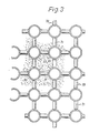
- the tubes 22 have radially outwardly directed pins 80 distributed uniformly on the circumference, which protrude into the flow space 72 and the catalyst bed and, as can be seen in FIG. 1, have a star shape in the longitudinal direction of the tubes are arranged.
- the pins that protrude into the flow space 72 are arranged at different heights; the pin 80 'in FIG. is arranged above the pin 80 "and this in turn is arranged above the pin 80"'.
- the length of the pins 80 is about 1 ⁇ 4 - 1 ⁇ 3 of the distance between two diagonally adjacent tubes, so z. B. the tubes 22 'and 22 "in Fig. 2nd
- the pins are preferably shot onto the tubes.
- They can also be designed as pins with a square cross section and with a head in the form of a rivet.
Landscapes
- Chemical & Material Sciences (AREA)
- Organic Chemistry (AREA)
- Chemical Kinetics & Catalysis (AREA)
- Devices And Processes Conducted In The Presence Of Fluids And Solid Particles (AREA)
- Organic Low-Molecular-Weight Compounds And Preparation Thereof (AREA)
Priority Applications (1)
| Application Number | Priority Date | Filing Date | Title |
|---|---|---|---|
| AT84105393T ATE32833T1 (de) | 1983-09-06 | 1984-05-12 | Stehender reaktor zur erzeugung von methanol. |
Applications Claiming Priority (4)
| Application Number | Priority Date | Filing Date | Title |
|---|---|---|---|
| DE3332049 | 1983-09-06 | ||
| DE19833332049 DE3332049A1 (de) | 1983-09-06 | 1983-09-06 | Stehender reaktor zur erzeugung von methanol |
| DE3344423 | 1983-12-08 | ||
| DE19833344423 DE3344423A1 (de) | 1983-12-08 | 1983-12-08 | Stehender reaktor zur erzeugung von methanol |
Publications (3)
| Publication Number | Publication Date |
|---|---|
| EP0155341A2 EP0155341A2 (de) | 1985-09-25 |
| EP0155341A3 EP0155341A3 (en) | 1986-04-30 |
| EP0155341B1 true EP0155341B1 (de) | 1988-03-09 |
Family
ID=25813755
Family Applications (1)
| Application Number | Title | Priority Date | Filing Date |
|---|---|---|---|
| EP84105393A Expired EP0155341B1 (de) | 1983-09-06 | 1984-05-12 | Stehender Reaktor zur Erzeugung von Methanol |
Country Status (6)
| Country | Link |
|---|---|
| US (1) | US4632587A (uk) |
| EP (1) | EP0155341B1 (uk) |
| DD (1) | DD220232A5 (uk) |
| DE (1) | DE3469680D1 (uk) |
| SU (1) | SU1327782A3 (uk) |
| UA (1) | UA5987A1 (uk) |
Families Citing this family (13)
| Publication number | Priority date | Publication date | Assignee | Title |
|---|---|---|---|---|
| US4743432A (en) * | 1984-11-16 | 1988-05-10 | M.A.N. Maschinenfabrik Augsburg-Nurnberg | Vertical reactor for the generation of methanol |
| FR2584733B1 (fr) * | 1985-07-12 | 1987-11-13 | Inst Francais Du Petrole | Procede ameliore de vapocraquage d'hydrocarbures |
| DE3880877T2 (de) * | 1987-02-26 | 1993-09-23 | Ammonia Casale Sa | System zur verbesserung der reaktorausbeute fuer exotherme synthese, insbesondere fuer die ammoniakreaktion. |
| NL8902250A (nl) * | 1989-09-08 | 1991-04-02 | Veg Gasinstituut Nv | Werkwijze voor het uitvoeren van een chemische reactie en daarbij te gebruiken reactor. |
| DE19539622C1 (de) * | 1995-10-16 | 1997-06-05 | Bayer Ag | Rohrreaktor |
| US5989500A (en) * | 1997-07-02 | 1999-11-23 | Phillips Petroleum Company | Reactor heat exchange system |
| US7108835B2 (en) * | 2003-10-08 | 2006-09-19 | Rentech, Inc. | Fischer-tropsch slurry reactor cooling tube arrangement |
| MY140160A (en) * | 2004-01-28 | 2009-11-30 | Shell Int Research | Heat exchanger for carrying out an exothermic reaction |
| CA2558955A1 (en) * | 2004-03-08 | 2005-09-15 | Shell Internationale Research Maatschappij B.V. | Filter system with filter means retractable into a housing |
| DE202007006812U1 (de) * | 2007-05-11 | 2008-09-18 | Man Dwe Gmbh | Kühlrohrreaktor |
| US8959769B2 (en) * | 2007-07-26 | 2015-02-24 | General Electric Company | Method and apparatus for heat recovery within a syngas cooler |
| US8815170B2 (en) * | 2008-08-21 | 2014-08-26 | Fluor Technologies Corporation | Devices and methods of heat removal from exothermic high temperature reaction processes |
| EP3839397A1 (de) * | 2019-12-20 | 2021-06-23 | Fores Engineering Srl | Verfahren und vorrichtung zum abkühlen von heissen gasen |
Citations (1)
| Publication number | Priority date | Publication date | Assignee | Title |
|---|---|---|---|---|
| DE3117077A1 (de) * | 1981-04-29 | 1982-11-18 | Linde Ag, 6200 Wiesbaden | Verfahren und vorrichtung zur entfernung unerwuenschter gasfoermiger bestandteile aus einem heissen abgas |
Family Cites Families (13)
| Publication number | Priority date | Publication date | Assignee | Title |
|---|---|---|---|---|
| US1920800A (en) * | 1931-08-07 | 1933-08-01 | Griscom Russell Co | Heat exchanger |
| US2149300A (en) * | 1938-02-12 | 1939-03-07 | Houdry Process Corp | Distribution and temperature control in chemical reactions |
| US2261293A (en) * | 1938-07-16 | 1941-11-04 | Houdry Process Corp | Heat exchange apparatus |
| US2280081A (en) * | 1939-01-18 | 1942-04-21 | Houdry Process Corp | Catalytic converter |
| US2356700A (en) * | 1942-03-11 | 1944-08-22 | Standard Oil Dev Co | Treating hydrocarbon fluids |
| DE914131C (de) * | 1951-12-11 | 1954-06-28 | Metallgesellschaft Ag | Kontaktofen |
| US2862480A (en) * | 1954-09-10 | 1958-12-02 | Babcock & Wilcox Co | Synthesis gas reactor and heat exchanger |
| DE1501640A1 (de) * | 1966-05-03 | 1969-11-06 | Schmidt Sche Heissdampfgmbh | Waermeaustauscher,insbesondere zum Kuehlen frischer Spaltgase und/oder Synthesegase |
| DE2549398A1 (de) * | 1975-11-04 | 1977-05-05 | Linde Ag | Reaktor |
| DE2848014A1 (de) * | 1978-11-06 | 1980-05-08 | Linde Ag | Reaktor zur durchfuehrung exothermer katalytischer reaktionen |
| CA1172832A (en) * | 1979-09-06 | 1984-08-21 | Hydrocarbon Research, Inc. | Reactor having dual upflow catalyst beds |
| DE3007203A1 (de) * | 1980-02-26 | 1981-09-10 | Linde Ag, 6200 Wiesbaden | Reaktor |
| US4298589A (en) * | 1980-06-17 | 1981-11-03 | The M. W. Kellogg Company | Split axial flow converter in ammonia synthesis |
-
1984
- 1984-05-12 EP EP84105393A patent/EP0155341B1/de not_active Expired
- 1984-05-12 DE DE8484105393T patent/DE3469680D1/de not_active Expired
- 1984-06-27 UA UA3753930A patent/UA5987A1/uk unknown
- 1984-06-27 SU SU843753930A patent/SU1327782A3/ru active
- 1984-07-09 DD DD84265063A patent/DD220232A5/de not_active IP Right Cessation
- 1984-08-06 US US06/637,759 patent/US4632587A/en not_active Expired - Fee Related
Patent Citations (1)
| Publication number | Priority date | Publication date | Assignee | Title |
|---|---|---|---|---|
| DE3117077A1 (de) * | 1981-04-29 | 1982-11-18 | Linde Ag, 6200 Wiesbaden | Verfahren und vorrichtung zur entfernung unerwuenschter gasfoermiger bestandteile aus einem heissen abgas |
Also Published As
| Publication number | Publication date |
|---|---|
| DE3469680D1 (en) | 1988-04-14 |
| UA5987A1 (uk) | 1994-12-29 |
| DD220232A5 (de) | 1985-03-27 |
| EP0155341A2 (de) | 1985-09-25 |
| US4632587A (en) | 1986-12-30 |
| EP0155341A3 (en) | 1986-04-30 |
| SU1327782A3 (ru) | 1987-07-30 |
Similar Documents
| Publication | Publication Date | Title |
|---|---|---|
| DE60205645T2 (de) | Wärmetauscher für isothermische chemische reaktor | |
| DE2222562C3 (de) | Reaktionsturm mit mehreren nacheinander radial durchstroemten ringfoermigen Reaktionskammern | |
| EP0155341B1 (de) | Stehender Reaktor zur Erzeugung von Methanol | |
| DE3146778C2 (uk) | ||
| EP0417428A2 (de) | Rohrbündel-Wärmetauscher | |
| DE2628180A1 (de) | Waermeuebertragungselement und duese fuer einen wirbelschichtreaktor | |
| EP0725675A1 (de) | Katalytischer reaktor für endotherme reaktionen | |
| DE2448832A1 (de) | Fluessigmetall/wasser-waermetauscher mit auswechselbaren rohrbuendeln | |
| DE3613508A1 (de) | Einrichtung zur vergasung feinzerteilter, insbesondere fester brennstoffe unter erhoehtem druck | |
| DE2631884A1 (de) | Dampf-kohlenwasserstoff-reformiereinrichtung | |
| DE3009850A1 (de) | Reaktorbehaelter | |
| DE2430161C2 (de) | Wärmetauscher mit kreisförmigem oder hexagonalem Querschnitt | |
| DE3332049C2 (uk) | ||
| DE2459472B1 (de) | Gasbeheizter dampferzeuger, insbesondere fuer kernreaktoranlagen | |
| DE3219297C2 (de) | Wärmetauscher, insbesondere Heissgaskühler für Helium | |
| DE3309695C2 (de) | Schachtkühler zum Trockenlöschen von Koks | |
| DE1927850A1 (de) | Vorrichtung zur Durchfuehrung von exothermen katalytischen Gasreaktionen | |
| DE2441706A1 (de) | Heizkessel mit gusseisernen gerippten rohren | |
| EP0281600A1 (de) | Reformer für die katalytische spaltung gasförmiger kohlenwasserstoffe. | |
| EP0111615A1 (de) | Wärmeübertragersystem, vorzugsweise für ein Prozessgas | |
| DE2754375C2 (de) | Abhitzekessel hinter chemischen Reaktoren | |
| DE692836C (de) | r katalytischer Gasreaktionen | |
| DE2517694C2 (de) | Wärmetauscher mit kreisförmigem oder hexagonalem Querschnitt mit einer Anzahl von Rohrbündeln | |
| DE2449190C2 (de) | Prozeßwärmetauscher für gasgekühlte Hochtemperaturreaktoren | |
| DD238041A5 (de) | Stehender reaktor zur erzeugung von methanol |
Legal Events
| Date | Code | Title | Description |
|---|---|---|---|
| PUAI | Public reference made under article 153(3) epc to a published international application that has entered the european phase |
Free format text: ORIGINAL CODE: 0009012 |
|
| AK | Designated contracting states |
Designated state(s): AT DE FR GB IT NL |
|
| RAP1 | Party data changed (applicant data changed or rights of an application transferred) |
Owner name: M.A.N. MASCHINENFABRIK AUGSBURG-NUERNBERG AKTIENGE |
|
| PUAL | Search report despatched |
Free format text: ORIGINAL CODE: 0009013 |
|
| 17P | Request for examination filed |
Effective date: 19860114 |
|
| AK | Designated contracting states |
Kind code of ref document: A3 Designated state(s): AT DE FR GB IT NL |
|
| RAP1 | Party data changed (applicant data changed or rights of an application transferred) |
Owner name: MAN GUTEHOFFNUNGSHUETTE GMBH |
|
| 17Q | First examination report despatched |
Effective date: 19870224 |
|
| D17Q | First examination report despatched (deleted) | ||
| GRAA | (expected) grant |
Free format text: ORIGINAL CODE: 0009210 |
|
| AK | Designated contracting states |
Kind code of ref document: B1 Designated state(s): AT DE FR GB IT NL |
|
| REF | Corresponds to: |
Ref document number: 32833 Country of ref document: AT Date of ref document: 19880315 Kind code of ref document: T |
|
| ITF | It: translation for a ep patent filed |
Owner name: BARZANO' E ZANARDO MILANO S.P.A. |
|
| REF | Corresponds to: |
Ref document number: 3469680 Country of ref document: DE Date of ref document: 19880414 |
|
| ET | Fr: translation filed | ||
| GBT | Gb: translation of ep patent filed (gb section 77(6)(a)/1977) | ||
| PLBE | No opposition filed within time limit |
Free format text: ORIGINAL CODE: 0009261 |
|
| STAA | Information on the status of an ep patent application or granted ep patent |
Free format text: STATUS: NO OPPOSITION FILED WITHIN TIME LIMIT |
|
| 26N | No opposition filed | ||
| ITTA | It: last paid annual fee | ||
| PGFP | Annual fee paid to national office [announced via postgrant information from national office to epo] |
Ref country code: DE Payment date: 19940419 Year of fee payment: 11 |
|
| PGFP | Annual fee paid to national office [announced via postgrant information from national office to epo] |
Ref country code: FR Payment date: 19940420 Year of fee payment: 11 |
|
| PGFP | Annual fee paid to national office [announced via postgrant information from national office to epo] |
Ref country code: GB Payment date: 19940421 Year of fee payment: 11 |
|
| PGFP | Annual fee paid to national office [announced via postgrant information from national office to epo] |
Ref country code: AT Payment date: 19940426 Year of fee payment: 11 |
|
| PGFP | Annual fee paid to national office [announced via postgrant information from national office to epo] |
Ref country code: NL Payment date: 19940531 Year of fee payment: 11 |
|
| PG25 | Lapsed in a contracting state [announced via postgrant information from national office to epo] |
Ref country code: GB Effective date: 19950512 Ref country code: AT Effective date: 19950512 |
|
| PG25 | Lapsed in a contracting state [announced via postgrant information from national office to epo] |
Ref country code: NL Effective date: 19951201 |
|
| GBPC | Gb: european patent ceased through non-payment of renewal fee |
Effective date: 19950512 |
|
| NLV4 | Nl: lapsed or anulled due to non-payment of the annual fee |
Effective date: 19951201 |
|
| PG25 | Lapsed in a contracting state [announced via postgrant information from national office to epo] |
Ref country code: DE Effective date: 19960201 |
|
| PG25 | Lapsed in a contracting state [announced via postgrant information from national office to epo] |
Ref country code: FR Effective date: 19960229 |
|
| REG | Reference to a national code |
Ref country code: FR Ref legal event code: ST |
|
| REG | Reference to a national code |
Ref country code: FR Ref legal event code: ST |