EP0155341B1 - Standing reactor for the production of methanol - Google Patents
Standing reactor for the production of methanol Download PDFInfo
- Publication number
- EP0155341B1 EP0155341B1 EP84105393A EP84105393A EP0155341B1 EP 0155341 B1 EP0155341 B1 EP 0155341B1 EP 84105393 A EP84105393 A EP 84105393A EP 84105393 A EP84105393 A EP 84105393A EP 0155341 B1 EP0155341 B1 EP 0155341B1
- Authority
- EP
- European Patent Office
- Prior art keywords
- reactor
- pipes
- catalyst bed
- catalyst
- cylindrical mantle
- Prior art date
- Legal status (The legal status is an assumption and is not a legal conclusion. Google has not performed a legal analysis and makes no representation as to the accuracy of the status listed.)
- Expired
Links
Images


Classifications
-
- B—PERFORMING OPERATIONS; TRANSPORTING
- B01—PHYSICAL OR CHEMICAL PROCESSES OR APPARATUS IN GENERAL
- B01J—CHEMICAL OR PHYSICAL PROCESSES, e.g. CATALYSIS OR COLLOID CHEMISTRY; THEIR RELEVANT APPARATUS
- B01J8/00—Chemical or physical processes in general, conducted in the presence of fluids and solid particles; Apparatus for such processes
- B01J8/02—Chemical or physical processes in general, conducted in the presence of fluids and solid particles; Apparatus for such processes with stationary particles, e.g. in fixed beds
- B01J8/04—Chemical or physical processes in general, conducted in the presence of fluids and solid particles; Apparatus for such processes with stationary particles, e.g. in fixed beds the fluid passing successively through two or more beds
- B01J8/0496—Heating or cooling the reactor
-
- B—PERFORMING OPERATIONS; TRANSPORTING
- B01—PHYSICAL OR CHEMICAL PROCESSES OR APPARATUS IN GENERAL
- B01J—CHEMICAL OR PHYSICAL PROCESSES, e.g. CATALYSIS OR COLLOID CHEMISTRY; THEIR RELEVANT APPARATUS
- B01J8/00—Chemical or physical processes in general, conducted in the presence of fluids and solid particles; Apparatus for such processes
- B01J8/02—Chemical or physical processes in general, conducted in the presence of fluids and solid particles; Apparatus for such processes with stationary particles, e.g. in fixed beds
- B01J8/04—Chemical or physical processes in general, conducted in the presence of fluids and solid particles; Apparatus for such processes with stationary particles, e.g. in fixed beds the fluid passing successively through two or more beds
- B01J8/0446—Chemical or physical processes in general, conducted in the presence of fluids and solid particles; Apparatus for such processes with stationary particles, e.g. in fixed beds the fluid passing successively through two or more beds the flow within the beds being predominantly vertical
- B01J8/0449—Chemical or physical processes in general, conducted in the presence of fluids and solid particles; Apparatus for such processes with stationary particles, e.g. in fixed beds the fluid passing successively through two or more beds the flow within the beds being predominantly vertical in two or more cylindrical beds
- B01J8/0453—Chemical or physical processes in general, conducted in the presence of fluids and solid particles; Apparatus for such processes with stationary particles, e.g. in fixed beds the fluid passing successively through two or more beds the flow within the beds being predominantly vertical in two or more cylindrical beds the beds being superimposed one above the other
-
- C—CHEMISTRY; METALLURGY
- C07—ORGANIC CHEMISTRY
- C07C—ACYCLIC OR CARBOCYCLIC COMPOUNDS
- C07C29/00—Preparation of compounds having hydroxy or O-metal groups bound to a carbon atom not belonging to a six-membered aromatic ring
- C07C29/15—Preparation of compounds having hydroxy or O-metal groups bound to a carbon atom not belonging to a six-membered aromatic ring by reduction of oxides of carbon exclusively
- C07C29/151—Preparation of compounds having hydroxy or O-metal groups bound to a carbon atom not belonging to a six-membered aromatic ring by reduction of oxides of carbon exclusively with hydrogen or hydrogen-containing gases
- C07C29/152—Preparation of compounds having hydroxy or O-metal groups bound to a carbon atom not belonging to a six-membered aromatic ring by reduction of oxides of carbon exclusively with hydrogen or hydrogen-containing gases characterised by the reactor used
-
- B—PERFORMING OPERATIONS; TRANSPORTING
- B01—PHYSICAL OR CHEMICAL PROCESSES OR APPARATUS IN GENERAL
- B01J—CHEMICAL OR PHYSICAL PROCESSES, e.g. CATALYSIS OR COLLOID CHEMISTRY; THEIR RELEVANT APPARATUS
- B01J2208/00—Processes carried out in the presence of solid particles; Reactors therefor
- B01J2208/00008—Controlling the process
- B01J2208/00017—Controlling the temperature
- B01J2208/00106—Controlling the temperature by indirect heat exchange
- B01J2208/00115—Controlling the temperature by indirect heat exchange with heat exchange elements inside the bed of solid particles
- B01J2208/00132—Tubes
-
- B—PERFORMING OPERATIONS; TRANSPORTING
- B01—PHYSICAL OR CHEMICAL PROCESSES OR APPARATUS IN GENERAL
- B01J—CHEMICAL OR PHYSICAL PROCESSES, e.g. CATALYSIS OR COLLOID CHEMISTRY; THEIR RELEVANT APPARATUS
- B01J2219/00—Chemical, physical or physico-chemical processes in general; Their relevant apparatus
- B01J2219/18—Details relating to the spatial orientation of the reactor
- B01J2219/185—Details relating to the spatial orientation of the reactor vertical
Definitions
- the invention relates to a standing reactor for the production of methanol, with a cylindrical housing with exchanger tubes passing through the catalyst bed in the interior of the housing and running parallel to the longitudinal axis of the reactor, as well as a gas-permeable bottom or network in the lower reactor section, in which the housing is separated by an upper one Hood is closed, the catalyst bed is enclosed by a cylindrical jacket within the housing, which can be lifted out of the housing with the catalyst bed in the longitudinal direction of the reactor when the hood is lifted.
- DE-A-3007203 describes a reactor for carrying out a catalytic methanol synthesis with a cylindrical housing which receives the catalyst bed resting on a perforated plate and is provided with exchanger tubes running in the bed for guiding a cooling fluid.
- the tubes are designed as fin tubes and run straight in the bed and parallel to the housing axis. The free ends of the exchanger tubes open into an upper or lower tube plate.
- a heat exchanger according to DE-A-1501640 is used in particular for cooling fresh cracked gases and / or synthesis gas and has a jacket made of fin tubes, namely the exchanger tubes are provided with fins such that closed geometric spaces are created.
- the reactor In the contact furnace known from DE-C-914131, the reactor is located in a cylindrical housing. The reactor cannot be lifted out of the housing, but only tube units can be lifted out.
- the known methanol reactors with the features of the preamble of the main claim compared with the object of the invention is to provide a reactor in which both the exchange of the catalyst filling and the monitoring and replacement of the heat exchanger tubes in the catalyst bed and the replacement of the catalyst plate or - network easily, with a structurally simple reactor structure.
- the flow conditions in the catalyst bed are to be improved to achieve a long service life of the exchanger tubes compared to known tubes for the same purpose.
- the invention provides the features of the characterizing part of the main claim.
- the features of the subclaims serve the further development and improvement of the features of the main claim.
- the advantage of the reactor according to the invention can be seen in the fact that the cylindrical jacket, which consists of fin tubes, with the catalyst filling can be removed from the housing with its pressure jacket and the insulating jacket, after which it is only possible to completely or partially loosen the catalyst base or network needs to allow the catalyst to freely escape down from the cylindrical jacket. If the catalyst base or network is closed again, the catalyst mass can easily be filled into the cylindrical fin tube jacket.
- the advantage of the fin exchanger tubes with pins projecting into the flow spaces is that the catalyst mass of the pins is relieved of the weight of the catalyst mass above the pins and this results in a loosening of the catalyst mass which improves the flow conditions within the catalyst bed. Furthermore, the pins on the tubes serve to increase the heat transfer from the catalyst mass to the tubes and thus to the exchange medium.
- peg walls e.g. B. the walls of melting chambers to support and hold the ramming mass or lining of the melting chamber.
- peg walls e.g. B. the walls of melting chambers to support and hold the ramming mass or lining of the melting chamber.
- the reactor according to the invention is not only suitable for the production of methanol, but other catalytic reactions can also be carried out in it.
- its housing G has an outer, cylindrical pressure jacket 1, which extends from the upper section to the lower section of the reactor and carries a flange 2, 3 on its upper and lower edge.
- the top of the housing G forms a hood 4, which is connected by its flange 5 to the flange 2 of the cylindrical pressure jacket, while the bottom 6 of the housing G is connected by its flange 7 to the flange 3.
- the pressure jacket 1 is lined with an insulating layer 8 which extends from the parting line between the flanges 2, 5 to the parting line of the flanges 3, 7.
- the hood 4 and the bottom 6 are in turn lined with insulating layers 9, 10.
- the design of the pressure jacket 1 and the hood 4 or the bottom 6 with their linings is such that the hood 4 can be removed from the pressure jacket 1 without difficulty. The same applies to the floor 6 if necessary.
- This has a cylindrical jacket which is closed on its circumference and formed from fin tubes 12.
- the upper and lower ends of the fin tubes 12 open into a reinforced tube section 14, 15, these tube sections opening into a lower distributor ring line 16 and an upper collecting ring line 17.
- the cooling medium for the heat exchanger 11 is supplied via one or more tubes 18 passing through the base 6 and its insulating layer 10, while the heated cooling medium is drawn off from the collecting ring line 17 via one or more tubes 19.
- this ring line extends over the inner, free cross section of this ring line or between the pipe sections 15, a catalyst network or floor 23 on which the catalyst mass rests, which lies between the Pipes 22 finds space and extends from the catalyst network or floor to about the level of the joint between the flanges between the flanges 2 and 5.
- the bottom 6 with its insulating layer 10 has the raw gas supply line 24, while the hood 4 with its lining 9 has the methanol gas discharge line 25.
- the raw gas flows through the catalyst bed 26 between the tubes 22 and the bent ends 20, 21 of the tubes 22 in order to be discharged through the tube 25 as methanol gas after the reaction with the aid of the catalyst.
- the heat exchanger 11 with its jacket and the catalyst mass can be removed from the top of the reactor.
- the catalyst mass can then be removed from the jacket and replaced by partially or completely loosening the catalyst network or base 23.
- the tubes of the heat exchanger 11 can be easily removed or installed outside of the housing upwards or downwards.
- an outer pressure jacket 51 is again provided, which is lined with an insulating layer 52.
- the jacket 51 has a flange 53 with which the flange 54 of a hood 55 can be connected.
- the raw gas is supplied through a line 56 approximately at the middle level of the reactor, which passes through the pressure jacket 51 and also its insulating layer 52.
- the insulating layer encloses a heat exchanger in the same way as in the embodiment according to FIG. 1.
- This has an outer fin tube jacket made of fin tubes 58, which are recessed at the level of line 56, so that the raw gas can enter the interior of the jacket. Also shown in Fig.
- a catalyst network 64 extends through the feed line 56, through which the tubes 61 pass.
- a second catalyst network 64a is located at the level or above the ring line 63a.
- the bottom 65 with its insulating layer 66 is connected in one piece to the jacket 51 and its insulating layer 52 and is penetrated by a line 67 discharging methanol gas, just as the hood 55 with its insulating layer 68 is penetrated by a line 69 .
- the tubes 22 and 61 have fins 70, 71 lying opposite one another in pairs and are arranged such that the fins of the tubes give rise to a closed flow space 72 for the gas flowing through the catalyst mass in space 72. Vagabonding of the gas in adjacent rooms and thus an uneven loading of the tubes 22, 61 is largely avoided.
- the catalyst gauzes 23, 64, 64a are partially opened, the almost completely closed spaces 72 can be used to successively empty the interior of the cylindrical jacket, which makes work easier.
- a cylindrical jacket is equivalent to an approximately cylindrical jacket.
- the tubes 22 have radially outwardly directed pins 80 distributed uniformly on the circumference, which protrude into the flow space 72 and the catalyst bed and, as can be seen in FIG. 1, have a star shape in the longitudinal direction of the tubes are arranged.
- the pins that protrude into the flow space 72 are arranged at different heights; the pin 80 'in FIG. is arranged above the pin 80 "and this in turn is arranged above the pin 80"'.
- the length of the pins 80 is about 1 ⁇ 4 - 1 ⁇ 3 of the distance between two diagonally adjacent tubes, so z. B. the tubes 22 'and 22 "in Fig. 2nd
- the pins are preferably shot onto the tubes.
- They can also be designed as pins with a square cross section and with a head in the form of a rivet.
Description
Die Erfindung betrifft einen stehenden Reaktor zur Herstellung von Methanol, mit einem zylindrischen Gehäuse mit das Katalysatorbett im Inneren des Gehäuses durchsetzenden, parallel zur Reaktorlängsachse verlaufenden Austauscherrohren sowie einem das Katalysatorbett tragenden, gasdurchlässigen Boden oder Netz im unteren Reaktorabschnitt, bei dem das Gehäuse durch eine obere Haube abgeschlossen ist, das Katalysatorbett von einem zylindrischen Mantel innerhalb des Gehäuses umschlossen ist, der bei abgehobener Haube mit dem Katalysatorbett in Längsrichtung des Reaktors aus dessen Gehäuse heraushebbar ist.The invention relates to a standing reactor for the production of methanol, with a cylindrical housing with exchanger tubes passing through the catalyst bed in the interior of the housing and running parallel to the longitudinal axis of the reactor, as well as a gas-permeable bottom or network in the lower reactor section, in which the housing is separated by an upper one Hood is closed, the catalyst bed is enclosed by a cylindrical jacket within the housing, which can be lifted out of the housing with the catalyst bed in the longitudinal direction of the reactor when the hood is lifted.
Aus der DE-A-2848014 sowie der DE-A-2549398 sind stehende Reaktoren zur Herstellung von Methanol nach dem Oberbegriff des Anspruchs 1 bekannt.From DE-A-2848014 and DE-A-2549398 standing reactors for the production of methanol are known according to the preamble of claim 1.
In der DE-A-3007203 wird ein Reaktor zur Durchführung einer katalytischen Methanolsynthese beschrieben mit einem zylindrischen Gehäuse, das die auf einem Lochblech ruhende Katalysatorschüttung aufnimmt und mit in der Schüttung verlaufenden Tauscherrohren zur Führung eines Kühlfluids versehen ist. Die Rohre sind als Flossenrohre ausgebildet und verlaufen geradlinig in der Schüttung sowie parallel zur Gehäuseachse. Die freien Enden der Tauscherrohre münden in einen oberen oder unteren Rohrboden.DE-A-3007203 describes a reactor for carrying out a catalytic methanol synthesis with a cylindrical housing which receives the catalyst bed resting on a perforated plate and is provided with exchanger tubes running in the bed for guiding a cooling fluid. The tubes are designed as fin tubes and run straight in the bed and parallel to the housing axis. The free ends of the exchanger tubes open into an upper or lower tube plate.
Ein Wärmetauscher nach der DE-A-1501640 dient insbesondere zum Kühlen von frischen Spaltgasen und/oder Synthesegas und weist einen Mantel aus Flossenrohren auf, und zwar sind die Austauscherrohre derart mit Flossen versehen, dass geschlossene geometrische Räume entstehen.A heat exchanger according to DE-A-1501640 is used in particular for cooling fresh cracked gases and / or synthesis gas and has a jacket made of fin tubes, namely the exchanger tubes are provided with fins such that closed geometric spaces are created.
Bei dem aus der DE-C-914131 bekannten Kontaktofen befindet sich der Reaktor in einem zylindrischen Gehäuse. Der Reaktor kann nicht aus dem Gehäuse herausgehoben werden, sondern es können lediglich jeweils Rohreinheiten herausgehoben werden.In the contact furnace known from DE-C-914131, the reactor is located in a cylindrical housing. The reactor cannot be lifted out of the housing, but only tube units can be lifted out.
Den bekannten Methanol-Reaktoren mit den Merkmalen des Gattungsbegriffes des Hauptanspruches gegenüber besteht die Aufgabe der Erfindung darin, einen Reaktor zu schaffen, bei dem sowohl der Austausch der Katalysatorfüllung wie auch das Überwachen und Auswechseln der Wärmetauscherrohre in dem Katalysatorbett und das Ersetzen des Katalysatorbodens oder -netzes leicht, bei konstruktiv einfachem Reaktoraufbau, erfolgen kann. Trotz dieser vorstehend genannten Forderungen sollen die Strömungsverhältnisse in dem Katalysatorbett zur Erzielung einer langen Lebensdauer der Tauscherrohre gegenüber bekannten Rohren für den gleichen Zweck verbessert werden.The known methanol reactors with the features of the preamble of the main claim compared with the object of the invention is to provide a reactor in which both the exchange of the catalyst filling and the monitoring and replacement of the heat exchanger tubes in the catalyst bed and the replacement of the catalyst plate or - network easily, with a structurally simple reactor structure. Despite these requirements mentioned above, the flow conditions in the catalyst bed are to be improved to achieve a long service life of the exchanger tubes compared to known tubes for the same purpose.
Zur Lösung dieser Aufgabe sieht die Erfindung die Merkmale des kennzeichnenden Teils des Hauptanspruches vor. Die Merkmale der Unteransprüche dienen der Weiterentwicklung und Verbesserung der Merkmale des Hauptanspruches.To achieve this object, the invention provides the features of the characterizing part of the main claim. The features of the subclaims serve the further development and improvement of the features of the main claim.
Der Vorteil des erfindungsgemässen Reaktors ist darin zu sehen, dass der zylindrische Mantel, der aus Flossenrohren besteht, mit der Katalysatorfüllung aus dem Gehäuse mit seinem Druckmantel und dem Isoliermantel geschlossen herausgenommen werden kann, wonach es nur des ganzen oder des partiellen Lösens des Katalysatorbodens oder -netzes bedarf, um den Katalysator frei nach unten aus dem zylindrischen Mantel entweichen zu lassen. Wird der Katalysatorboden oder -netz wieder geschlossen, so kann die Füllung der Katalysatormasse in den zylindrischen Flossenrohrmantel leicht erfolgen.The advantage of the reactor according to the invention can be seen in the fact that the cylindrical jacket, which consists of fin tubes, with the catalyst filling can be removed from the housing with its pressure jacket and the insulating jacket, after which it is only possible to completely or partially loosen the catalyst base or network needs to allow the catalyst to freely escape down from the cylindrical jacket. If the catalyst base or network is closed again, the catalyst mass can easily be filled into the cylindrical fin tube jacket.
Gleiches gilt auch hinsichtlich des Auswechselns der Tauscherrohre. Diese brauchen nicht aus dem Gehäuse des Katalysators entfernt zu werden, vielmehr können sie leicht zugänglich einzeln aus dem oben im ganzen Querschnitt offenen zylindrischen Mantel ausgebaut bzw. in diesen eingebaut werden. Die Strömungsverhältnisse innerhalb des Katalysatorbettes werden dadurch verbessert, dass zwischen den Rohren gleichmässige geometrische Strömungsräume als Aufnahmeräume für die Katalysatormasse gebildet werden, die in sich abgeschlossen sind und ein Vagabundieren des Gases in benachbarte Räume verhindern. Hierdurch wird eine gleichmässige Beaufschlagung der Austauscherrohre erzielt.The same applies to the exchange of the exchanger tubes. These do not need to be removed from the housing of the catalytic converter, rather they can be easily removed individually from the cylindrical shell, which is open across the entire cross section, or can be built into this. The flow conditions within the catalyst bed are improved in that even geometric flow spaces are formed between the tubes as receiving spaces for the catalyst mass, which are self-contained and prevent the gas from vagabonding into adjacent spaces. This results in a uniform loading of the exchanger tubes.
Der Vorteil der Flossenaustauscherrohre mit in die Strömungsräume ragenden Stiften besteht darin, dass die Katalysatormasse der Stifte eine Entlastung von dem Gewicht der Katalysatormasse oberhalb der Stifte bekommt und hierdurch eine Auflockerung der Katalysatormasse gegeben ist, durch die die Strömungsverhältnisse innerhalb des Katalysatorbettes verbessert werden. Desweiteren dienen die Stifte an den Rohren zur Erhöhung des Wärmeüberganges von der Katalysatormasse auf die Rohre und damit auf das Austauschermedium.The advantage of the fin exchanger tubes with pins projecting into the flow spaces is that the catalyst mass of the pins is relieved of the weight of the catalyst mass above the pins and this results in a loosening of the catalyst mass which improves the flow conditions within the catalyst bed. Furthermore, the pins on the tubes serve to increase the heat transfer from the catalyst mass to the tubes and thus to the exchange medium.
An sich ist es in der Technik bekannt, Wände zu bestiften, so z. B. die Wände von Schmelzkammern, um die Stampfmasse oder Auskleidung der Schmelzkammer zu stützen und zu halten. Hier liegt somit eine andere Aufgabe und Wirkung als beim Erfindungsgegenstand vor.As such, it is known in the art to peg walls, e.g. B. the walls of melting chambers to support and hold the ramming mass or lining of the melting chamber. Here there is therefore a different task and effect than the object of the invention.
Der erfindungsgemässe Reaktor eignet sich nicht nur für die Erzeugung von Methanol, sondern in ihm können auch andere katalytische Umsetzungen durchgeführt werden.The reactor according to the invention is not only suitable for the production of methanol, but other catalytic reactions can also be carried out in it.
Auf der Zeichnung sind Ausführungsbeispiele des Reaktors nach der Erfindung dargestellt, und zwar zeigt
- Fig. eine erste Ausführungsform eines Reaktors im Längsschnitt mit seinem Reaktorbett,
- Fig.2 eine weitere Ausführungsform eines Reaktors, bei welchem der Innenraum des zylindrischen Mantels zwei Reaktorbetten aufnimmt,
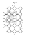
- Fig. einen horizontalen Querschnitt durch das Katalysatorbett bzw. die Katalysatorbetten der beiden Ausführungsformen nach Fig. 1 und 2
- Fig.4 einen weiteren Horizontalschnitt durch den Reaktor und
- Fig. einen Schnitt nach der Linie V - V der Fig. 4.
- 1 shows a first embodiment of a reactor in longitudinal section with its reactor bed,
- 2 shows a further embodiment of a reactor, in which the interior of the cylindrical jacket accommodates two reactor beds,
- 1 shows a horizontal cross section through the catalyst bed or the catalyst beds of the two embodiments according to FIGS. 1 and 2
- 4 shows a further horizontal section through the reactor and
- Fig. A section along the line V - V of Fig. 4th
Bei der Ausführungsform des stehenden Reaktors nach Fig.1, weist dessen Gehäuse G einen äusseren, zylindrischen Druckmantel 1 auf, der sich von dem oberen Abschnitt zum unteren Abschnitt des Reaktors erstreckt und an seinem oberen und unteren Rand je einen Flansch 2, 3 trägt. Den Abschluss des Gehäuses G nach oben bildet eine Haube 4, die mittels ihres Flansches 5 mit dem Flansch 2 des zylindrischen Druckmantels verbunden ist, während der Boden 6 des Gehäuses G mit seinem Flansch 7 mit dem Flansch 3 verbunden ist.In the embodiment of the standing reactor according to FIG. 1, its housing G has an outer, cylindrical pressure jacket 1, which extends from the upper section to the lower section of the reactor and carries a
Der Druckmantel 1 ist mit einer Isolierlage 8 ausgekleidet, die von der Trennfuge zwischen den Flanschen 2, 5 zur Trennfuge der Flanschen 3, 7 reicht. Die Haube 4 und der Boden 6 sind ihrerseits mit Isolierlagen 9, 10 ausgekleidet. Die Ausbildung des Druckmantels 1 und der Haube 4 bzw. des Bodens 6 mit ihren Auskleidungen ist so getroffen, dass die Haube 4 von dem Druckmantel 1 ohne Schwierigkeiten entfernt werden kann. Das gleiche gilt, falls dies notwendig ist, für den Boden 6.The pressure jacket 1 is lined with an
Die Isolierlage 8, die den zylindrischen Druckmantel 1 auskleidet, nimmt den mittleren Abschnitt eines Wärmetauschers 11 auf. Dieser weist einen, an seinem Umfang geschlossenen, aus Flossenrohren 12 gebildeten zylindrischen Mantel auf. Das obere und untere Ende der Flossenrohre 12 mündet in einen verstärkten Rohrabschnitt 14, 15, wobei diese Rohrabschnitte in eine untere Verteilerringleitung 16 und eine obere Sammelringleitung 17 münden. Das Kühlmedium für den Wärmetauscher 11 wird bei der Ausführungsform nach Fig.1 über eine oder mehrere, den Boden 6 und dessen Isolierlage 10 durchsetzende Rohre 18 zugeführt, während das erwärmte Kühlmedium aus der Sammelringleitung 17 über ein oder mehrere Rohre 19 abgezogen wird.The
In die verstärkten Rohrabschnitte 14, 15 der Flossenrohre 12 des zylindrischen Wärmeaustauschermantels münden die in horizontale Ebenen abgebogenen Enden 20, 21 der senkrechten und parallel zur Längsachse des Reaktors verlaufenden Tauscherrohre 22 des Wärmetauschers 11, so dass ein Rohrbündel an Tauscherrohren gebildet wird.In the reinforced
Auf Höhe der Ringleitung 16 oder aber, wie in Fig. dargestellt ist, etwas oberhalb dieser Ringleitung erstreckt sich über den inneren, freien Querschnitt dieser Ringleitung oder zwischen den Rohrabschnitten 15 ein Katalysatornetz oder -boden 23, auf dem die Katalysatormasse aufliegt, die zwischen den Rohren 22 Platz findet und sich von dem Katalysatornetz oder -boden bis etwa auf Höhe der Trennfuge zwischen den Flanschen zwischen den Flanschen 2 und 5 erstreckt.At the level of the ring line 16 or, as shown in Fig., Somewhat above this ring line extends over the inner, free cross section of this ring line or between the
Der Boden 6 mit seiner lsolierlage 10 weist die Rohgaszuführungsleitung 24 auf, während die Haube 4 mit ihrer Auskleidung 9 die Methanolgasabzugsleitung 25 besitzt. Das Rohgas durchströmt das Katalysatorbett 26 zwischen den Rohren 22 und den abgebogenen Enden 20, 21 der Rohre 22, um nach der Reaktion mit Hilfe des Katalysators als Methanolgas durch das Rohr 25 abgeführt zu werden.The bottom 6 with its
Der an seinem Umfang geschlossene zylindrische Mantel aus Flossenrohren 12 liegt eng an der Isolierlage 8 des Reaktors an. Bei Lösen der Haube 4 mit ihrer Isolierlage 9 kann der Wärmetauscher 11 mit seinem Mantel und der Katalysatormasse nach oben aus dem Reaktor entfernt werden. Daraufhin kann durch partielles oder gänzliches Lösen des Katalysatornetzes oder -bodens 23 die Katalysatormasse aus dem Mantel abgezogen und ausgetauscht werden. Die Rohre des Wärmetauschers 11 können leicht ausserhalb des Gehäuses nach oben oder unten aus- bzw. in diesen eingebaut werden.The cylindrical jacket made of
Bei der Ausführungsform nach Fig. 2 ist wiederum ein äusserer Druckmantel 51 vorgesehen, der von einer Isolierlage 52 ausgekleidet ist. Der Mantel 51 besitzt einen Flansch 53, mit dem der Flansch 54 einer Haube 55 verbindbar ist. Die Zuführung des Rohgases erfolgt durch eine Leitung 56 etwa auf mittlerer Höhe des Reaktors, die den Druckmantel 51, wie auch dessen Isolierlage 52 durchsetzt. Die Isolierlage umschliesst in gleicher Weise wie bei der Ausführungsform nach Fig. 1 einen Wärmetauscher. Dieser weist einen äusseren Flossenrohrmantel aus Flossenrohren 58 auf, die auf Höhe der Leitung 56 ausgespart sind, so dass das Rohgas in das Innere des Mantels einzutreten vermag. Auch sind in Fig. mit ihren Enden 59, 60 abgebogene, zu einem Rohrbündel zusammengefasste Tauscherrohre 61 vorgesehen, die in verstärkte Abschnitte 62, 63 der Flossenrohre 58 münden, die ihrerseits in einer Ringleitung 62a, 63a enden, denen das Kühlmedium zu- bzw. von ihnen abgeführt wird.In the embodiment according to FIG. 2, an
Oberhalb der Zuführungsleitung 56 erstreckt sich, von den Rohren 61 durchsetzt, ein Katalysatornetz 64. Auf Höhe oder oberhalb der Ringleitung 63a befindet sich ein zweites Katalysatornetz 64a. Bei dem in Fig. dargestellten Ausführungsbeispiel ist der Boden 65 mit seiner Isolierlage 66 einteilig mit dem Mantel 51 und seiner Isolierlage 52 verbunden und wird von einer Methanolgas abführenden Leitung 67 ebenso durchsetzt, wie die Haube 55 mit ihrer Isolierlage 68 von einer Leitung 69 durchsetzt wird.A catalyst network 64 extends through the
Bei der Ausführungsform nach Fig.1 und 2 besitzen die Rohre 22 bzw. 61 paarweise gegenüberliegende Flossen 70, 71 und sind derart angeordnet, dass die Flossen der Rohre einen geschlossenen Strömungsraum 72 für das die Katalysatormasse in dem Raum 72 durchströmende Gas entstehen lassen. Ein Vagabundieren des Gases in benachbarte Räume und damit eine ungleichmässige Beaufschlagung der Rohre 22, 61 wird hierdurch weitgehend vermieden. Beim partiellen Öffnen der Katalysatornetze 23, 64, 64a kann mit Hilfe der annähernd vollkommen abgeschlossenen Räume 72 ein arbeitserleichterndes sukzessives Entleeren des Innenraumes des zylindrischen Mantels erreicht werden.In the embodiment according to FIGS. 1 and 2, the
An sich ist die Aufnahme zweier übereinandergelegener Katalysatorbetten in einem Reaktor aus der DE-A-3022815 bekannt. Insofern sollen die darauf gerichteten und im Zusammenhang damit genannten Merkmale nur in Verbindung mit weiteren Merkmalen der Erfindung Gültigkeit haben.The inclusion of two superimposed catalyst beds in a reactor is known from DE-A-3022815. To that extent features aimed at and mentioned in connection therewith are only valid in connection with further features of the invention.
Einem zylindrischen Mantel ist als äquivalent ein annähernd zylindrischer Mantel gleichzusetzen.A cylindrical jacket is equivalent to an approximately cylindrical jacket.
Die Rohre 22 weisen gemäss Fig.4 und Fig.5 winkelmässig gleichartig am Umfang verteilte, radial auswärts gerichtete Stifte 80 auf, die in den Strömungsraum 72 und das Katalysatorbett ragen und, wie Fig.1 erkennen lässt, in Längsrichtung der Rohre sternförmig an diesen angeordnet sind. Die Stifte, die in den Strömungsraum 72 ragen, sind in unterschiedlicher Höhe angeordnet; so ist der Stift 80' in Fig. oberhalb des Stiftes 80" und dieser wiederum oberhalb des Stiftes 80"' angeordnet.According to FIGS. 4 and 5, the
Die Länge der Stifte 80 beträgt etwa ¼ - ⅓ des Abstandes zwischen zwei diagonal benachbarten Rohren, so z. B. der Rohre 22' und 22" in Fig. 2.The length of the
Die Stifte sind vorzugsweise auf die Rohre aufgeschossen.The pins are preferably shot onto the tubes.
Sie können auch als im Querschnitt quadratische Stifte wie auch mit einem Kopf in Form eines Nietes ausgebildet sein.They can also be designed as pins with a square cross section and with a head in the form of a rivet.
Claims (7)
Priority Applications (1)
| Application Number | Priority Date | Filing Date | Title |
|---|---|---|---|
| AT84105393T ATE32833T1 (en) | 1983-09-06 | 1984-05-12 | STANDING REACTOR FOR PRODUCTION OF METHANOL. |
Applications Claiming Priority (4)
| Application Number | Priority Date | Filing Date | Title |
|---|---|---|---|
| DE3332049 | 1983-09-06 | ||
| DE19833332049 DE3332049A1 (en) | 1983-09-06 | 1983-09-06 | Upright reactor for methanol production |
| DE3344423 | 1983-12-08 | ||
| DE19833344423 DE3344423A1 (en) | 1983-12-08 | 1983-12-08 | Vertical reactor for the production of methanol |
Publications (3)
| Publication Number | Publication Date |
|---|---|
| EP0155341A2 EP0155341A2 (en) | 1985-09-25 |
| EP0155341A3 EP0155341A3 (en) | 1986-04-30 |
| EP0155341B1 true EP0155341B1 (en) | 1988-03-09 |
Family
ID=25813755
Family Applications (1)
| Application Number | Title | Priority Date | Filing Date |
|---|---|---|---|
| EP84105393A Expired EP0155341B1 (en) | 1983-09-06 | 1984-05-12 | Standing reactor for the production of methanol |
Country Status (6)
| Country | Link |
|---|---|
| US (1) | US4632587A (en) |
| EP (1) | EP0155341B1 (en) |
| DD (1) | DD220232A5 (en) |
| DE (1) | DE3469680D1 (en) |
| SU (1) | SU1327782A3 (en) |
| UA (1) | UA5987A1 (en) |
Families Citing this family (13)
| Publication number | Priority date | Publication date | Assignee | Title |
|---|---|---|---|---|
| US4743432A (en) * | 1984-11-16 | 1988-05-10 | M.A.N. Maschinenfabrik Augsburg-Nurnberg | Vertical reactor for the generation of methanol |
| FR2584733B1 (en) * | 1985-07-12 | 1987-11-13 | Inst Francais Du Petrole | IMPROVED PROCESS FOR VAPOCRACKING HYDROCARBONS |
| ATE89191T1 (en) * | 1987-02-26 | 1993-05-15 | Ammonia Casale Sa | SYSTEM FOR IMPROVING THE REACTOR YIELD FOR EXOTHERMAL SYNTHESIS, ESPECIALLY FOR THE AMMONIA REACTION. |
| NL8902250A (en) * | 1989-09-08 | 1991-04-02 | Veg Gasinstituut Nv | METHOD FOR PERFORMING A CHEMICAL REACTION AND REACTOR TO BE USED THERE |
| DE19539622C1 (en) * | 1995-10-16 | 1997-06-05 | Bayer Ag | Tubular reactor |
| US5989500A (en) * | 1997-07-02 | 1999-11-23 | Phillips Petroleum Company | Reactor heat exchange system |
| US7108835B2 (en) * | 2003-10-08 | 2006-09-19 | Rentech, Inc. | Fischer-tropsch slurry reactor cooling tube arrangement |
| MY140160A (en) * | 2004-01-28 | 2009-11-30 | Shell Int Research | Heat exchanger for carrying out an exothermic reaction |
| US20070199887A1 (en) * | 2004-03-08 | 2007-08-30 | Anne Boer | Filter System With Filter Means Retractable Into A Housing |
| DE202007006812U1 (en) * | 2007-05-11 | 2008-09-18 | Man Dwe Gmbh | Cooling tube reactor |
| US8959769B2 (en) * | 2007-07-26 | 2015-02-24 | General Electric Company | Method and apparatus for heat recovery within a syngas cooler |
| CA2734582A1 (en) * | 2008-08-21 | 2010-02-25 | Fluor Technologies Corporation | Devices and methods of heat removal from exothermic high temperature reaction processes |
| EP3839397A1 (en) * | 2019-12-20 | 2021-06-23 | Fores Engineering Srl | Method and device for cooling hot gases |
Citations (1)
| Publication number | Priority date | Publication date | Assignee | Title |
|---|---|---|---|---|
| DE3117077A1 (en) * | 1981-04-29 | 1982-11-18 | Linde Ag, 6200 Wiesbaden | Process and apparatus for removing undesirable gaseous constituents from a hot exhaust gas |
Family Cites Families (13)
| Publication number | Priority date | Publication date | Assignee | Title |
|---|---|---|---|---|
| US1920800A (en) * | 1931-08-07 | 1933-08-01 | Griscom Russell Co | Heat exchanger |
| US2149300A (en) * | 1938-02-12 | 1939-03-07 | Houdry Process Corp | Distribution and temperature control in chemical reactions |
| US2261293A (en) * | 1938-07-16 | 1941-11-04 | Houdry Process Corp | Heat exchange apparatus |
| US2280081A (en) * | 1939-01-18 | 1942-04-21 | Houdry Process Corp | Catalytic converter |
| US2356700A (en) * | 1942-03-11 | 1944-08-22 | Standard Oil Dev Co | Treating hydrocarbon fluids |
| DE914131C (en) * | 1951-12-11 | 1954-06-28 | Metallgesellschaft Ag | Contact furnace |
| US2862480A (en) * | 1954-09-10 | 1958-12-02 | Babcock & Wilcox Co | Synthesis gas reactor and heat exchanger |
| DE1501640A1 (en) * | 1966-05-03 | 1969-11-06 | Schmidt Sche Heissdampfgmbh | Heat exchangers, especially for cooling fresh fission gases and / or synthesis gases |
| DE2549398A1 (en) * | 1975-11-04 | 1977-05-05 | Linde Ag | Exothermic catalytic reactor - e.g. for prodn. of methane from hydrogen and carbon dioxide, recovery of methanol or formaldehyde |
| DE2848014A1 (en) * | 1978-11-06 | 1980-05-08 | Linde Ag | Reactor for exothermic catalytic reactions - having central tube containing cooling coils surrounded by catalyst bed, allowing coils to be easily removed |
| CA1172832A (en) * | 1979-09-06 | 1984-08-21 | Hydrocarbon Research, Inc. | Reactor having dual upflow catalyst beds |
| DE3007203A1 (en) * | 1980-02-26 | 1981-09-10 | Linde Ag, 6200 Wiesbaden | Methanol synthesis reactor - with catalyst packing contg. coolant pipes aligned parallel with flow of synthesis gas to minimise drop in gas pressure |
| US4298589A (en) * | 1980-06-17 | 1981-11-03 | The M. W. Kellogg Company | Split axial flow converter in ammonia synthesis |
-
1984
- 1984-05-12 DE DE8484105393T patent/DE3469680D1/en not_active Expired
- 1984-05-12 EP EP84105393A patent/EP0155341B1/en not_active Expired
- 1984-06-27 UA UA3753930A patent/UA5987A1/en unknown
- 1984-06-27 SU SU843753930A patent/SU1327782A3/en active
- 1984-07-09 DD DD84265063A patent/DD220232A5/en not_active IP Right Cessation
- 1984-08-06 US US06/637,759 patent/US4632587A/en not_active Expired - Fee Related
Patent Citations (1)
| Publication number | Priority date | Publication date | Assignee | Title |
|---|---|---|---|---|
| DE3117077A1 (en) * | 1981-04-29 | 1982-11-18 | Linde Ag, 6200 Wiesbaden | Process and apparatus for removing undesirable gaseous constituents from a hot exhaust gas |
Also Published As
| Publication number | Publication date |
|---|---|
| DD220232A5 (en) | 1985-03-27 |
| EP0155341A2 (en) | 1985-09-25 |
| UA5987A1 (en) | 1994-12-29 |
| SU1327782A3 (en) | 1987-07-30 |
| US4632587A (en) | 1986-12-30 |
| EP0155341A3 (en) | 1986-04-30 |
| DE3469680D1 (en) | 1988-04-14 |
Similar Documents
| Publication | Publication Date | Title |
|---|---|---|
| DE60205645T2 (en) | HEAT EXCHANGER FOR ISOTHERMIC CHEMICAL REACTOR | |
| DE2222562C3 (en) | Reaction tower with several annular reaction chambers through which radial flow flows one after the other | |
| EP0155341B1 (en) | Standing reactor for the production of methanol | |
| DE3146778C2 (en) | ||
| EP0417428A2 (en) | Tube bundle heat exchanger | |
| DE2628180A1 (en) | HEAT TRANSFER ELEMENT AND NOZZLE FOR A FLUID BED REACTOR | |
| WO1995011745A1 (en) | Catalytic reactor for endothermic reactions | |
| DE2448832A1 (en) | LIQUID METAL / WATER HEAT EXCHANGER WITH REPLACEABLE PIPE COILS | |
| DE2631884A1 (en) | STEAM HYDROCARBON REFORMING DEVICE | |
| DE3009850A1 (en) | Gasification reactor lining - with two rings of cooling tubes embedded in several refractory layers | |
| DE2430161C2 (en) | Heat exchangers with a circular or hexagonal cross-section | |
| DE3332049C2 (en) | ||
| DE2459472B1 (en) | GAS HEATED STEAM GENERATOR, IN PARTICULAR FOR NUCLEAR REACTOR PLANTS | |
| DE3219297C2 (en) | Heat exchangers, in particular hot gas coolers for helium | |
| DE3309695C2 (en) | Chute cooler for dry extinguishing of coke | |
| DE1927850A1 (en) | Device for carrying out exothermic catalytic gas reactions | |
| DE2441706A1 (en) | HEATING BOILER WITH CAST-IRON RIBBED PIPES | |
| EP0281600A1 (en) | Reformer for catalytic cracking of gaseous hydrocarbons. | |
| EP0111615A1 (en) | Heat transfer system, especially for a process gas | |
| DE2754375C2 (en) | Waste heat boiler behind chemical reactors | |
| DE692836C (en) | r catalytic gas reactions | |
| DE2517694C2 (en) | Heat exchangers with a circular or hexagonal cross-section with a number of tube bundles | |
| DE2449190C2 (en) | Process heat exchanger for gas-cooled high-temperature reactors | |
| DD238041A5 (en) | STANDING REACTOR FOR GENERATING METHANOL | |
| DE819684C (en) | Contact furnace for carrying out exothermic reactions under pressure, especially for the conversion of carbon oxide |
Legal Events
| Date | Code | Title | Description |
|---|---|---|---|
| PUAI | Public reference made under article 153(3) epc to a published international application that has entered the european phase |
Free format text: ORIGINAL CODE: 0009012 |
|
| AK | Designated contracting states |
Designated state(s): AT DE FR GB IT NL |
|
| RAP1 | Party data changed (applicant data changed or rights of an application transferred) |
Owner name: M.A.N. MASCHINENFABRIK AUGSBURG-NUERNBERG AKTIENGE |
|
| PUAL | Search report despatched |
Free format text: ORIGINAL CODE: 0009013 |
|
| 17P | Request for examination filed |
Effective date: 19860114 |
|
| AK | Designated contracting states |
Kind code of ref document: A3 Designated state(s): AT DE FR GB IT NL |
|
| RAP1 | Party data changed (applicant data changed or rights of an application transferred) |
Owner name: MAN GUTEHOFFNUNGSHUETTE GMBH |
|
| 17Q | First examination report despatched |
Effective date: 19870224 |
|
| D17Q | First examination report despatched (deleted) | ||
| GRAA | (expected) grant |
Free format text: ORIGINAL CODE: 0009210 |
|
| AK | Designated contracting states |
Kind code of ref document: B1 Designated state(s): AT DE FR GB IT NL |
|
| REF | Corresponds to: |
Ref document number: 32833 Country of ref document: AT Date of ref document: 19880315 Kind code of ref document: T |
|
| ITF | It: translation for a ep patent filed |
Owner name: BARZANO' E ZANARDO MILANO S.P.A. |
|
| REF | Corresponds to: |
Ref document number: 3469680 Country of ref document: DE Date of ref document: 19880414 |
|
| ET | Fr: translation filed | ||
| GBT | Gb: translation of ep patent filed (gb section 77(6)(a)/1977) | ||
| PLBE | No opposition filed within time limit |
Free format text: ORIGINAL CODE: 0009261 |
|
| STAA | Information on the status of an ep patent application or granted ep patent |
Free format text: STATUS: NO OPPOSITION FILED WITHIN TIME LIMIT |
|
| 26N | No opposition filed | ||
| ITTA | It: last paid annual fee | ||
| PGFP | Annual fee paid to national office [announced via postgrant information from national office to epo] |
Ref country code: DE Payment date: 19940419 Year of fee payment: 11 |
|
| PGFP | Annual fee paid to national office [announced via postgrant information from national office to epo] |
Ref country code: FR Payment date: 19940420 Year of fee payment: 11 |
|
| PGFP | Annual fee paid to national office [announced via postgrant information from national office to epo] |
Ref country code: GB Payment date: 19940421 Year of fee payment: 11 |
|
| PGFP | Annual fee paid to national office [announced via postgrant information from national office to epo] |
Ref country code: AT Payment date: 19940426 Year of fee payment: 11 |
|
| PGFP | Annual fee paid to national office [announced via postgrant information from national office to epo] |
Ref country code: NL Payment date: 19940531 Year of fee payment: 11 |
|
| PG25 | Lapsed in a contracting state [announced via postgrant information from national office to epo] |
Ref country code: GB Effective date: 19950512 Ref country code: AT Effective date: 19950512 |
|
| PG25 | Lapsed in a contracting state [announced via postgrant information from national office to epo] |
Ref country code: NL Effective date: 19951201 |
|
| GBPC | Gb: european patent ceased through non-payment of renewal fee |
Effective date: 19950512 |
|
| NLV4 | Nl: lapsed or anulled due to non-payment of the annual fee |
Effective date: 19951201 |
|
| PG25 | Lapsed in a contracting state [announced via postgrant information from national office to epo] |
Ref country code: DE Effective date: 19960201 |
|
| PG25 | Lapsed in a contracting state [announced via postgrant information from national office to epo] |
Ref country code: FR Effective date: 19960229 |
|
| REG | Reference to a national code |
Ref country code: FR Ref legal event code: ST |
|
| REG | Reference to a national code |
Ref country code: FR Ref legal event code: ST |