EP0154716A1 - Circuit pour mesure électrothermique du niveau avec compensation de la température ambiante - Google Patents
Circuit pour mesure électrothermique du niveau avec compensation de la température ambiante Download PDFInfo
- Publication number
- EP0154716A1 EP0154716A1 EP84116136A EP84116136A EP0154716A1 EP 0154716 A1 EP0154716 A1 EP 0154716A1 EP 84116136 A EP84116136 A EP 84116136A EP 84116136 A EP84116136 A EP 84116136A EP 0154716 A1 EP0154716 A1 EP 0154716A1
- Authority
- EP
- European Patent Office
- Prior art keywords
- voltage
- comparator
- capacitor
- heating
- time
- Prior art date
- Legal status (The legal status is an assumption and is not a legal conclusion. Google has not performed a legal analysis and makes no representation as to the accuracy of the status listed.)
- Granted
Links
Images

Classifications
-
- G—PHYSICS
- G01—MEASURING; TESTING
- G01F—MEASURING VOLUME, VOLUME FLOW, MASS FLOW OR LIQUID LEVEL; METERING BY VOLUME
- G01F23/00—Indicating or measuring liquid level or level of fluent solid material, e.g. indicating in terms of volume or indicating by means of an alarm
- G01F23/22—Indicating or measuring liquid level or level of fluent solid material, e.g. indicating in terms of volume or indicating by means of an alarm by measuring physical variables, other than linear dimensions, pressure or weight, dependent on the level to be measured, e.g. by difference of heat transfer of steam or water
- G01F23/24—Indicating or measuring liquid level or level of fluent solid material, e.g. indicating in terms of volume or indicating by means of an alarm by measuring physical variables, other than linear dimensions, pressure or weight, dependent on the level to be measured, e.g. by difference of heat transfer of steam or water by measuring variations of resistance of resistors due to contact with conductor fluid
- G01F23/246—Indicating or measuring liquid level or level of fluent solid material, e.g. indicating in terms of volume or indicating by means of an alarm by measuring physical variables, other than linear dimensions, pressure or weight, dependent on the level to be measured, e.g. by difference of heat transfer of steam or water by measuring variations of resistance of resistors due to contact with conductor fluid thermal devices
Definitions
- the invention relates to a circuit arrangement for electrothermal, ambient temperature-compensated level measurement according to the preamble of claim 1.
- the resistance probe is connected to the constant current source with each start of measurement (start of a measurement period), which is actuated by a sequence control (delay circuit) during the heating-up time.
- the latter is related to the comparator.
- the comparator is connected on the one hand to an inverter connected to the resistance probe and to a resistance capacitor element connected in parallel, in such a way that the comparator outputs an output signal to a monitoring device as soon as the voltage drop across the resistance capacitor element is equal to that of the inverter (DE- OS 27 40 289).
- the measuring principle is based on the fact that the change in resistance of the resistance probe, which is more or less surrounded by the fluid to be measured, is measured, which occurs at the end of a heating time due to a constant current.
- the difference in voltage U 1 at the end of the heating-up time compared to an initial voltage U o at the beginning thereof.
- the inverter supplies a voltage VU 0 which charges the capacitor of the resistance capacitor element. This then discharges according to a known law which is determined by the resistance value and the capacity.
- the comparator records the point in time at which the voltage profile of the capacitor (charging curve), which can be represented as a straight line, intersects the curve of the inverted voltage VU. At a point in time determined by the sequence control, the comparator is controlled such that a comparison is made between the value of the inverted voltage VU 0 at the connections of the resistance capacitor element and the value of the voltage across the inverter.
- a monitoring device connected to the output of the comparator can trigger an alarm when a predefinable threshold value is exceeded.
- the level of a liquid into which the resistance probe is immersed can also be displayed, using numerical or analog display instruments.
- This circuit arrangement is relatively complex, in particular because of the inverter provided.
- this circuit arrangement for forming numerical display values can be integrated into an analog-digital converter.
- the measuring voltage and the compensation voltage can also be fed into an analog-digital converter, with the output of which digital memories and a digital arithmetic circuit are connected to form the quotient.
- This circuit arrangement is relatively complex because of the means for forming the quotient. This applies to the execution of the evaluation circuit in analog technology to form the quotient and especially in the execution in digital technology, since here the analog-digital converter must first convert the measurement voltage and the compensation voltage before their digitized variables can be evaluated further.
- the present invention is therefore based on the object of developing a circuit arrangement of the type mentioned at the outset in such a way that it is suitable for outputting digitized fill level values with a simple structure and high accuracy and for this purpose it is particularly easy to integrate into a corresponding converter.
- the ambient temperature compensation or the normalization of the temperature difference detected on the resistance probe between heating voltage U 1 and starting voltage U 0 is based on the starting voltage U 0 by comparing the detected heating voltage to the previously detected and subsequently integrated initial voltage.
- the temperature response of the resistance probe is compensated for by forming a quotient.
- the comparator performing this comparison can expediently be made as part of an analog-digital converter which operates according to the sawtooth method and which digitizes with a counting frequency the time between the reaching of the heating voltage by the integrated initial voltage on the one hand and the beginning of the comparison.
- the integrator can be constructed with little effort and precise work with an operational amplifier and a capacitor in its feedback branch.
- the accuracy of the measuring principle according to the first variant can be increased by using a converter which works according to the two-ramp method (dual-slope converter with zero point correction).
- a second variant for solving the problem according to the invention is specified in the characterizing part of claim 4.
- the simplest means are used to form a quotient or normalize the starting voltage U 0 .
- the normalized value is recorded as the time between actuation of the second sampling and holding element or sampling of the heating voltage and switching over of the comparator. As in the first variant, this time can also be converted into a digital level value using the sawtooth method in an integrated analog-digital converter.
- the comparison between the initial voltage and the heating voltage, which is sensed in a time-variable manner according to the resistance and the capacitor, is carried out particularly inexpensively here: Both sampling and holding elements and the resistor discharging the capacitor of the second holding element are located directly at the inputs of the comparator provided for this purpose.
- the time marked by switching the comparator does not include the difference between the heating voltage and the starting voltage standardized to the starting voltage, but a logarithmic value of the quotient heating voltage to starting voltage. With a relatively small linearity error, however, the logarithm of this quotient corresponds to the quotient itself.
- the linearity deviation can be accepted in many cases, since the characteristic curve of the resistance probe has to be adapted to the respective measurement location, in particular a motor vehicle tank.
- circuit arrangement according to the second variant of the invention can be further simplified by the measures according to claim 6. - There is therefore no need for a sampling switch and the associated control.
- This third variant has the additional advantages that lower demands on the comparator and the sampling! switches must be set, i.e. correspondingly less complex elements are sufficient.
- a comparator the input of which is charged with the initial voltage discharged by a resistance capacitor element and then the discharged heating voltage, a comparison is made with a constant reference voltage.
- the comparator controls a forward-backward counter, which counts a count value according to the logarithm from the quotient between the heating voltage and the starting voltage. - Fluctuations in the reference voltage and the so-called offset voltage of the comparator are not included in the count value if these values do not change during a measuring period.
- an output signal for minimum fill level can be set.
- the circuit arrangement in the third variant can be expanded so that it is additionally suitable for emitting a warning signal when a warning level is exceeded or fallen below.
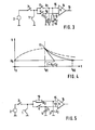
- FIG. 1 shows a first variant of the evaluation circuit for evaluating the voltage drop occurring at a resistance probe 1 for level measurement.
- the resistance probe is heated by a constant current source 2 via a controlled switch 3 with a clocked constant current.
- the switch 3 like other switches shown in FIG. 1 and explained below, is controlled by a sequence control (not shown).
- a first scanning and holding element consisting of a scanning switch 4 and a are connected to the resistance probe Storage capacitor 5, and a second sample and hold element consisting of a sampling switch 6 and a storage capacitor 7, connected.
- the first sample and hold element 4, 5 is connected to an input (+) of an integrator, which consists of an operational amplifier 8, a capacitor 9 in the feedback branch and a resistor 10 at a feedback input (-).
- a reset switch 11 is shown parallel to the capacitor 9.
- An output 12 of the integrator is coupled to a first input 13 of a comparator 14.
- the second input 15 of the comparator is connected to the output of the second sample and hold g l ed 6 , 7 .
- the output of the comparator is connected to a control input 16 of a presettable down counter 17, into which 18 count frequency pulses are fed via a count frequency input.
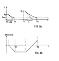
- the controlled switch 3 is closed at the beginning of a heating-up time t 0 , as a result of which the initial voltage U o drops at the resistance probe, see FIG. 2.
- This initial voltage is stored in the storage capacitor 5 by briefly closing the sampling switch 4.
- the capacitor 9 of the integrator is initially short-circuited, so that the integration does not start yet. This takes place only after the second sampling switch 6 is briefly closed shortly before the end of the heating-up time at time t 01 and the heating voltage U 1 then reached is held in the storage capacitor 7.
- the reset switch 11 is opened and the voltage at the output 12 of the integrator therefore rises linearly with an increase which is proportional to the value of the output voltage U o .
- the rate of increase or the rate of integration results from the time constant
- the measuring sequence is also to be controlled with the counting frequency f, an accuracy of ⁇ 1% for typical applications is required for the counting frequency.
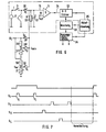
- the evaluation circuit according to FIG. 3 requires significantly less effort than that in FIG. 1.
- the integrator was dispensed with. Instead, the first sample and hold element with the storage capacitor 5 is connected directly to the first input 13 of the compensator 14.
- the storage capacitor 7 of the second sample and hold element which, as in FIG. 1, is directly coupled to the second input 15 of the comparator, is bridged here by a resistor R 2 , which bears the reference number 19.
- the resistor 19 is switched so that it discharges the storage capacitor 7, with the time constant
- the temperature compensation of the heating voltage also takes place here.
- the influence of the time constant T as described above, can be derived from the reference voltage ratio be compensated.
- the evaluation circuit according to FIG. 3 becomes the quotient formed and not as with the evaluation circuit 0 according to FIG. 1 .
- the time t 02 is formed in logarithmic and not in a linear dependence from the voltage ratio mentioned with the evaluation circuit according to FIG. 3. Approximately, however, conditions similar to those in the circuit arrangement according to FIG. 1 result, since can be expressed as
- the linearity deviation is less than 5%.
- the linearity can be improved to 1.5% by adding a quadratic link;
- the linearization can also take place instead by adapting the characteristic of the resistance probe.
- the storage capacitor 7 is thus discharged via the resistor 19 and the resistance probe 1 from the time t 01 , when the constant current is switched off with the controlled switch 3. Conversely, the storage capacitor 7 is also charged beforehand via the resistor 12, as a result of which higher-frequency interference can be suppressed.
- the switched off constant current source does not generate any significant residual current that leads to an offset voltage at the probe.
- the feed lines to the measuring probe are relatively short in order not to pick up any major disturbances.
- the time constant T is small compared to the time constant with which the temperature at the resistance probe changes.
- the up-down counter 23 counts upwards controlled by the sequence controller 25.
- a reference voltage ratio can be formed in the manner already indicated, namely as a time difference t 4 - t 3 analogous to the time difference described above
- the circuit part in FIG. 6 is provided, which is fed with the voltage U 2 . It is a voltage divider with the divider resistor 26 and the adjustable divider resistor 27.
- the voltage U min can be tapped at the common connection point between the two divider resistors.
- the voltage U 2 is sampled using a sampling switch 28 or S 2 .
- the voltage U min is queried with the sampling switch 28 1 or S 3 .
- the switches are actuated by the sequence controller 25 following the switches 3 and S 1 , see the pulse diagram in FIG. 7.
- the discharge of the capacitor 21 until the reference voltage U ref is reached then results in the following times:
- a further variable can then be formed to form a warning signal when a warning level is exceeded or fallen below.
- another voltage divider is used, which in FIG. 6 forms the voltage U W with the fixed divider resistor 30 and the adjustable divider resistor 31 from the voltage U 2 , S 4 can be scanned and charges the storage capacitor 21.
- the following relationship is finally formed, which signals the exceeding or falling below a warning level:
- the warning level min does not change if the output signal for the minimum fill level is adjusted.
- the function block 33 controls the function block 34 with output signal generators for level-proportional signals such as frequency, duty cycle, current or voltage by means of a digital-to-analog converter. Furthermore, the output signal generator forms level warning signals e.g. for reserve warning in motor vehicles.
Landscapes
- Physics & Mathematics (AREA)
- Thermal Sciences (AREA)
- Fluid Mechanics (AREA)
- General Physics & Mathematics (AREA)
- Measurement Of Resistance Or Impedance (AREA)
- Measurement Of Levels Of Liquids Or Fluent Solid Materials (AREA)
Applications Claiming Priority (2)
| Application Number | Priority Date | Filing Date | Title |
|---|---|---|---|
| DE19843408824 DE3408824A1 (de) | 1984-03-10 | 1984-03-10 | Schaltungsanordnung zur elektrothermischen, umgebungstemperatur-kompensierten fuellstandsmessung |
| DE3408824 | 1984-03-10 |
Publications (2)
| Publication Number | Publication Date |
|---|---|
| EP0154716A1 true EP0154716A1 (fr) | 1985-09-18 |
| EP0154716B1 EP0154716B1 (fr) | 1988-06-29 |
Family
ID=6230108
Family Applications (1)
| Application Number | Title | Priority Date | Filing Date |
|---|---|---|---|
| EP84116136A Expired EP0154716B1 (fr) | 1984-03-10 | 1984-12-21 | Circuit pour mesure électrothermique du niveau avec compensation de la température ambiante |
Country Status (4)
| Country | Link |
|---|---|
| US (1) | US4633491A (fr) |
| EP (1) | EP0154716B1 (fr) |
| JP (1) | JPS60207008A (fr) |
| DE (2) | DE3408824A1 (fr) |
Cited By (2)
| Publication number | Priority date | Publication date | Assignee | Title |
|---|---|---|---|---|
| DE3538181A1 (de) * | 1985-10-26 | 1987-04-30 | Messer Griesheim Gmbh | Vorrichtung zur automatischen begrenzung des fuellstandes kryogener fluessigkeiten |
| FR2681136A1 (fr) * | 1991-09-05 | 1993-03-12 | Sagem | Procede et circuit de controle du niveau d'un liquide dans un carter. |
Families Citing this family (17)
| Publication number | Priority date | Publication date | Assignee | Title |
|---|---|---|---|---|
| FR2599835B1 (fr) * | 1986-06-04 | 1988-08-26 | Bendix Electronics Sa | Procede et dispositif de mesure du niveau de la surface libre d'un liquide |
| JPH0342527U (fr) * | 1989-09-01 | 1991-04-22 | ||
| JP2820530B2 (ja) * | 1989-09-28 | 1998-11-05 | エンドレス ウント ハウザー ゲゼルシャフト ミット ベシュレンクテル ハフツング ウント コンパニー | センサ信号を処理するための装置 |
| DE3932479A1 (de) * | 1989-09-28 | 1991-04-11 | Endress Hauser Gmbh Co | Anordnung zur verarbeitung von sensorsignalen |
| US5111692A (en) * | 1990-03-27 | 1992-05-12 | Fluid Components, Inc. | Temperature compensated liquid level and fluid flow sensor |
| US5321633A (en) * | 1990-04-10 | 1994-06-14 | Yazaki Corporation | Heat radiating type liquid level sensing system and the method therefor |
| DE4016970A1 (de) * | 1990-05-25 | 1991-11-28 | Vdo Schindling | Verfahren und schaltungsanordnung zum ermitteln eines fluessigkeits-fuellstandes in einem fluessigkeitsbehaelter |
| JP2548252Y2 (ja) * | 1990-10-15 | 1997-09-17 | 株式会社カンセイ | 液面位検出装置 |
| JP2518169B2 (ja) * | 1991-04-09 | 1996-07-24 | 株式会社村田製作所 | 液面検知装置 |
| US5228340A (en) * | 1991-05-01 | 1993-07-20 | Yazaki Corporation | Method and apparatus for heat radiating type level sensor measurement of liquid level |
| US5291534A (en) * | 1991-06-22 | 1994-03-01 | Toyoda Koki Kabushiki Kaisha | Capacitive sensing device |
| DE4232043A1 (de) * | 1992-09-24 | 1994-03-31 | Siemens Ag | Verfahren und Einrichtung zur Füllstandsüberwachung sowie Verwendung dieser im Dauerbetrieb |
| JP3208742B2 (ja) * | 1992-11-13 | 2001-09-17 | 株式会社鷹山 | メモリデバイス |
| DE19754126A1 (de) * | 1997-12-05 | 1999-06-17 | Siemens Ag | Schaltungsanordnung zur Ansteuerung einer elektrischen Antriebseinheit |
| JP4359843B2 (ja) * | 2004-10-14 | 2009-11-11 | 横河電機株式会社 | 出力回路 |
| JP5701528B2 (ja) * | 2010-07-16 | 2015-04-15 | オリンパス株式会社 | 生体状態量測定装置 |
| JP5583153B2 (ja) * | 2012-01-26 | 2014-09-03 | 株式会社東芝 | 液面レベル検知装置及び方法 |
Citations (4)
| Publication number | Priority date | Publication date | Assignee | Title |
|---|---|---|---|---|
| DE2946585A1 (de) * | 1979-11-19 | 1981-05-27 | Vdo Adolf Schindling Ag, 6000 Frankfurt | Einrichtung zum elektrischen ueberwachen des niveaus einer in einem behaelter enthaltenen fluessigkeit |
| DE2740289B2 (de) * | 1976-10-06 | 1981-06-04 | Jaeger, Levallois-Perret, Hauts-de-Seine | Vorrichtung zur Überwachung des Niveaus einer in einem Behälter enthaltenen flüssigkeit |
| US4356728A (en) * | 1979-05-21 | 1982-11-02 | E.D. Veglia | Device for measuring the level of a liquid |
| DE3133421A1 (de) * | 1981-08-24 | 1983-03-10 | Vdo Adolf Schindling Ag, 6000 Frankfurt | Einrichtung zum elektrischen ueberwachen des niveaus einer in einem behaelter enthaltenen fluessigkeit |
Family Cites Families (4)
| Publication number | Priority date | Publication date | Assignee | Title |
|---|---|---|---|---|
| DE2510356C2 (de) * | 1975-03-10 | 1984-03-15 | Siemens AG, 1000 Berlin und 8000 München | Einrichtung zur Überwachung des Flüssigkeitsstandes in einem Behälter |
| DE2607187C3 (de) * | 1976-02-23 | 1986-07-10 | Krautkrämer GmbH, 5000 Köln | Verfahren zur Messung des zeitlichen Impulsabstandes von zwei elektrischen Impulsen |
| US4397031A (en) * | 1980-12-04 | 1983-08-02 | Weber Paul A | Time delay computer |
| FR2514134A2 (fr) * | 1981-10-07 | 1983-04-08 | Jaeger | Perfectionnements aux dispositifs de controle de niveau du liquide contenu dans un reservoir |
-
1984
- 1984-03-10 DE DE19843408824 patent/DE3408824A1/de not_active Withdrawn
- 1984-12-21 EP EP84116136A patent/EP0154716B1/fr not_active Expired
- 1984-12-21 DE DE8484116136T patent/DE3472451D1/de not_active Expired
-
1985
- 1985-03-11 US US06/710,168 patent/US4633491A/en not_active Expired - Fee Related
- 1985-03-11 JP JP60046715A patent/JPS60207008A/ja active Pending
Patent Citations (4)
| Publication number | Priority date | Publication date | Assignee | Title |
|---|---|---|---|---|
| DE2740289B2 (de) * | 1976-10-06 | 1981-06-04 | Jaeger, Levallois-Perret, Hauts-de-Seine | Vorrichtung zur Überwachung des Niveaus einer in einem Behälter enthaltenen flüssigkeit |
| US4356728A (en) * | 1979-05-21 | 1982-11-02 | E.D. Veglia | Device for measuring the level of a liquid |
| DE2946585A1 (de) * | 1979-11-19 | 1981-05-27 | Vdo Adolf Schindling Ag, 6000 Frankfurt | Einrichtung zum elektrischen ueberwachen des niveaus einer in einem behaelter enthaltenen fluessigkeit |
| DE3133421A1 (de) * | 1981-08-24 | 1983-03-10 | Vdo Adolf Schindling Ag, 6000 Frankfurt | Einrichtung zum elektrischen ueberwachen des niveaus einer in einem behaelter enthaltenen fluessigkeit |
Cited By (2)
| Publication number | Priority date | Publication date | Assignee | Title |
|---|---|---|---|---|
| DE3538181A1 (de) * | 1985-10-26 | 1987-04-30 | Messer Griesheim Gmbh | Vorrichtung zur automatischen begrenzung des fuellstandes kryogener fluessigkeiten |
| FR2681136A1 (fr) * | 1991-09-05 | 1993-03-12 | Sagem | Procede et circuit de controle du niveau d'un liquide dans un carter. |
Also Published As
| Publication number | Publication date |
|---|---|
| US4633491A (en) | 1986-12-30 |
| JPS60207008A (ja) | 1985-10-18 |
| EP0154716B1 (fr) | 1988-06-29 |
| DE3472451D1 (en) | 1988-08-04 |
| DE3408824A1 (de) | 1985-09-12 |
Similar Documents
| Publication | Publication Date | Title |
|---|---|---|
| EP0154716B1 (fr) | Circuit pour mesure électrothermique du niveau avec compensation de la température ambiante | |
| EP0219725B1 (fr) | Procédé pour compenser les tensions perturbatrices dans un circuit d'électrodes destiné à mesurer les débits par induction magnétique | |
| EP0139874B1 (fr) | Circuit pour la mesure thermoélectrique du niveau de remplissage | |
| DE2740289C3 (de) | Vorrichtung zur Überwachung des Niveaus einer in einem Behälter enthaltenen Flüssigkeit | |
| DE2364517C2 (de) | Spannungs/Frequenz-Umsetzer | |
| DE3905824C2 (fr) | ||
| EP0166034B1 (fr) | Procédé et dispositif de mesure électrothermique de niveau avec compensation de température ambiante | |
| DE10333154A1 (de) | Verfahren und Schaltungsanordnung zum Auswerten einer Messkapazität | |
| DE3037340A1 (de) | Treiber fuer hitzdraht-luftmengen-messer | |
| EP0173833A2 (fr) | Montage et procédé pour la mesure et la digitalisation d'une résistance | |
| EP0376024B1 (fr) | Procédé et dispositif de correction des tolérances de manufacture des éléments d'un circuit de traitement de signaux | |
| EP0250028B1 (fr) | Dispositif de montage pour la compensation de dérivés dépendants ou non de la température d'un capteur capacitif | |
| EP0927351B1 (fr) | Dispositif pour mesurer la qualite de l'air | |
| DE2547725B2 (de) | Verfahren zur Analog-Digital-Umwandlung einer Gleichspannung und Schaltungsanordnung zur Durchführung des Verfahrens | |
| DE4241702A1 (en) | Analogue=to=digital converter for electric motor speed control - counts clock pulses produced during period of PWM signal obtd. from error comparison with triangular wave | |
| EP0285047A2 (fr) | Circuit pour la mise en forme d'un signal de mesure en un signal rectangulaire | |
| DE4101819A1 (de) | Messvorrichtung zur elektrischen messung eines widerstandes sowie zugehoeriges messverfahren | |
| DE4401949C1 (de) | Einrichtung zum multiplikativen Korrigieren eines elektrischen Meßsignals | |
| EP0561054A1 (fr) | Appareil et procédé pour mesurer la constante de temps d'un capteur de déplacement | |
| DE2460079B2 (de) | Verfahren zur Bestimmung der Stellung des Schleifen eines Potentiometers und Schaltungsanordnung zur Durchführung des Verfahrens | |
| DE3915880C2 (fr) | ||
| DE102022201923B3 (de) | Verfahren und Schaltungsanordnung zur Ermittlung einer Induktivität einer Messspule und Verwendung dafür | |
| DE2839123C2 (de) | Spannungs-Frequenz-Wandler | |
| EP0129132A1 (fr) | Montage de mesure pour détecter une différence de température | |
| DE4229539A1 (de) | Einrichtung zur Erfassung des Tastverhältnisses eines Signals |
Legal Events
| Date | Code | Title | Description |
|---|---|---|---|
| PUAI | Public reference made under article 153(3) epc to a published international application that has entered the european phase |
Free format text: ORIGINAL CODE: 0009012 |
|
| AK | Designated contracting states |
Designated state(s): DE FR GB IT NL SE |
|
| 17P | Request for examination filed |
Effective date: 19851007 |
|
| 17Q | First examination report despatched |
Effective date: 19870219 |
|
| GRAA | (expected) grant |
Free format text: ORIGINAL CODE: 0009210 |
|
| AK | Designated contracting states |
Kind code of ref document: B1 Designated state(s): DE FR GB IT NL SE |
|
| GBT | Gb: translation of ep patent filed (gb section 77(6)(a)/1977) | ||
| REF | Corresponds to: |
Ref document number: 3472451 Country of ref document: DE Date of ref document: 19880804 |
|
| ET | Fr: translation filed | ||
| ITF | It: translation for a ep patent filed |
Owner name: STUDIO JAUMANN |
|
| ITTA | It: last paid annual fee | ||
| PLBE | No opposition filed within time limit |
Free format text: ORIGINAL CODE: 0009261 |
|
| STAA | Information on the status of an ep patent application or granted ep patent |
Free format text: STATUS: NO OPPOSITION FILED WITHIN TIME LIMIT |
|
| 26N | No opposition filed | ||
| PG25 | Lapsed in a contracting state [announced via postgrant information from national office to epo] |
Ref country code: GB Effective date: 19891221 |
|
| PG25 | Lapsed in a contracting state [announced via postgrant information from national office to epo] |
Ref country code: SE Effective date: 19891222 |
|
| PG25 | Lapsed in a contracting state [announced via postgrant information from national office to epo] |
Ref country code: NL Effective date: 19900701 |
|
| GBPC | Gb: european patent ceased through non-payment of renewal fee | ||
| NLV4 | Nl: lapsed or anulled due to non-payment of the annual fee | ||
| PG25 | Lapsed in a contracting state [announced via postgrant information from national office to epo] |
Ref country code: FR Effective date: 19900831 |
|
| PG25 | Lapsed in a contracting state [announced via postgrant information from national office to epo] |
Ref country code: DE Effective date: 19900901 |
|
| REG | Reference to a national code |
Ref country code: FR Ref legal event code: ST |
|
| EUG | Se: european patent has lapsed |
Ref document number: 84116136.7 Effective date: 19900830 |