EP0154716A1 - Circuit for electrothermal level measurement with ambient temperature compensation - Google Patents
Circuit for electrothermal level measurement with ambient temperature compensation Download PDFInfo
- Publication number
- EP0154716A1 EP0154716A1 EP84116136A EP84116136A EP0154716A1 EP 0154716 A1 EP0154716 A1 EP 0154716A1 EP 84116136 A EP84116136 A EP 84116136A EP 84116136 A EP84116136 A EP 84116136A EP 0154716 A1 EP0154716 A1 EP 0154716A1
- Authority
- EP
- European Patent Office
- Prior art keywords
- voltage
- comparator
- capacitor
- heating
- time
- Prior art date
- Legal status (The legal status is an assumption and is not a legal conclusion. Google has not performed a legal analysis and makes no representation as to the accuracy of the status listed.)
- Granted
Links
Images

Classifications
-
- G—PHYSICS
- G01—MEASURING; TESTING
- G01F—MEASURING VOLUME, VOLUME FLOW, MASS FLOW OR LIQUID LEVEL; METERING BY VOLUME
- G01F23/00—Indicating or measuring liquid level or level of fluent solid material, e.g. indicating in terms of volume or indicating by means of an alarm
- G01F23/22—Indicating or measuring liquid level or level of fluent solid material, e.g. indicating in terms of volume or indicating by means of an alarm by measuring physical variables, other than linear dimensions, pressure or weight, dependent on the level to be measured, e.g. by difference of heat transfer of steam or water
- G01F23/24—Indicating or measuring liquid level or level of fluent solid material, e.g. indicating in terms of volume or indicating by means of an alarm by measuring physical variables, other than linear dimensions, pressure or weight, dependent on the level to be measured, e.g. by difference of heat transfer of steam or water by measuring variations of resistance of resistors due to contact with conductor fluid
- G01F23/246—Indicating or measuring liquid level or level of fluent solid material, e.g. indicating in terms of volume or indicating by means of an alarm by measuring physical variables, other than linear dimensions, pressure or weight, dependent on the level to be measured, e.g. by difference of heat transfer of steam or water by measuring variations of resistance of resistors due to contact with conductor fluid thermal devices
Definitions
- the invention relates to a circuit arrangement for electrothermal, ambient temperature-compensated level measurement according to the preamble of claim 1.
- the resistance probe is connected to the constant current source with each start of measurement (start of a measurement period), which is actuated by a sequence control (delay circuit) during the heating-up time.
- the latter is related to the comparator.
- the comparator is connected on the one hand to an inverter connected to the resistance probe and to a resistance capacitor element connected in parallel, in such a way that the comparator outputs an output signal to a monitoring device as soon as the voltage drop across the resistance capacitor element is equal to that of the inverter (DE- OS 27 40 289).
- the measuring principle is based on the fact that the change in resistance of the resistance probe, which is more or less surrounded by the fluid to be measured, is measured, which occurs at the end of a heating time due to a constant current.
- the difference in voltage U 1 at the end of the heating-up time compared to an initial voltage U o at the beginning thereof.
- the inverter supplies a voltage VU 0 which charges the capacitor of the resistance capacitor element. This then discharges according to a known law which is determined by the resistance value and the capacity.
- the comparator records the point in time at which the voltage profile of the capacitor (charging curve), which can be represented as a straight line, intersects the curve of the inverted voltage VU. At a point in time determined by the sequence control, the comparator is controlled such that a comparison is made between the value of the inverted voltage VU 0 at the connections of the resistance capacitor element and the value of the voltage across the inverter.
- a monitoring device connected to the output of the comparator can trigger an alarm when a predefinable threshold value is exceeded.
- the level of a liquid into which the resistance probe is immersed can also be displayed, using numerical or analog display instruments.
- This circuit arrangement is relatively complex, in particular because of the inverter provided.
- this circuit arrangement for forming numerical display values can be integrated into an analog-digital converter.
- the measuring voltage and the compensation voltage can also be fed into an analog-digital converter, with the output of which digital memories and a digital arithmetic circuit are connected to form the quotient.
- This circuit arrangement is relatively complex because of the means for forming the quotient. This applies to the execution of the evaluation circuit in analog technology to form the quotient and especially in the execution in digital technology, since here the analog-digital converter must first convert the measurement voltage and the compensation voltage before their digitized variables can be evaluated further.
- the present invention is therefore based on the object of developing a circuit arrangement of the type mentioned at the outset in such a way that it is suitable for outputting digitized fill level values with a simple structure and high accuracy and for this purpose it is particularly easy to integrate into a corresponding converter.
- the ambient temperature compensation or the normalization of the temperature difference detected on the resistance probe between heating voltage U 1 and starting voltage U 0 is based on the starting voltage U 0 by comparing the detected heating voltage to the previously detected and subsequently integrated initial voltage.
- the temperature response of the resistance probe is compensated for by forming a quotient.
- the comparator performing this comparison can expediently be made as part of an analog-digital converter which operates according to the sawtooth method and which digitizes with a counting frequency the time between the reaching of the heating voltage by the integrated initial voltage on the one hand and the beginning of the comparison.
- the integrator can be constructed with little effort and precise work with an operational amplifier and a capacitor in its feedback branch.
- the accuracy of the measuring principle according to the first variant can be increased by using a converter which works according to the two-ramp method (dual-slope converter with zero point correction).
- a second variant for solving the problem according to the invention is specified in the characterizing part of claim 4.
- the simplest means are used to form a quotient or normalize the starting voltage U 0 .
- the normalized value is recorded as the time between actuation of the second sampling and holding element or sampling of the heating voltage and switching over of the comparator. As in the first variant, this time can also be converted into a digital level value using the sawtooth method in an integrated analog-digital converter.
- the comparison between the initial voltage and the heating voltage, which is sensed in a time-variable manner according to the resistance and the capacitor, is carried out particularly inexpensively here: Both sampling and holding elements and the resistor discharging the capacitor of the second holding element are located directly at the inputs of the comparator provided for this purpose.
- the time marked by switching the comparator does not include the difference between the heating voltage and the starting voltage standardized to the starting voltage, but a logarithmic value of the quotient heating voltage to starting voltage. With a relatively small linearity error, however, the logarithm of this quotient corresponds to the quotient itself.
- the linearity deviation can be accepted in many cases, since the characteristic curve of the resistance probe has to be adapted to the respective measurement location, in particular a motor vehicle tank.
- circuit arrangement according to the second variant of the invention can be further simplified by the measures according to claim 6. - There is therefore no need for a sampling switch and the associated control.
- This third variant has the additional advantages that lower demands on the comparator and the sampling! switches must be set, i.e. correspondingly less complex elements are sufficient.
- a comparator the input of which is charged with the initial voltage discharged by a resistance capacitor element and then the discharged heating voltage, a comparison is made with a constant reference voltage.
- the comparator controls a forward-backward counter, which counts a count value according to the logarithm from the quotient between the heating voltage and the starting voltage. - Fluctuations in the reference voltage and the so-called offset voltage of the comparator are not included in the count value if these values do not change during a measuring period.
- an output signal for minimum fill level can be set.
- the circuit arrangement in the third variant can be expanded so that it is additionally suitable for emitting a warning signal when a warning level is exceeded or fallen below.
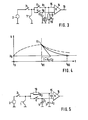
- FIG. 1 shows a first variant of the evaluation circuit for evaluating the voltage drop occurring at a resistance probe 1 for level measurement.
- the resistance probe is heated by a constant current source 2 via a controlled switch 3 with a clocked constant current.
- the switch 3 like other switches shown in FIG. 1 and explained below, is controlled by a sequence control (not shown).
- a first scanning and holding element consisting of a scanning switch 4 and a are connected to the resistance probe Storage capacitor 5, and a second sample and hold element consisting of a sampling switch 6 and a storage capacitor 7, connected.
- the first sample and hold element 4, 5 is connected to an input (+) of an integrator, which consists of an operational amplifier 8, a capacitor 9 in the feedback branch and a resistor 10 at a feedback input (-).
- a reset switch 11 is shown parallel to the capacitor 9.
- An output 12 of the integrator is coupled to a first input 13 of a comparator 14.
- the second input 15 of the comparator is connected to the output of the second sample and hold g l ed 6 , 7 .
- the output of the comparator is connected to a control input 16 of a presettable down counter 17, into which 18 count frequency pulses are fed via a count frequency input.
- the controlled switch 3 is closed at the beginning of a heating-up time t 0 , as a result of which the initial voltage U o drops at the resistance probe, see FIG. 2.
- This initial voltage is stored in the storage capacitor 5 by briefly closing the sampling switch 4.
- the capacitor 9 of the integrator is initially short-circuited, so that the integration does not start yet. This takes place only after the second sampling switch 6 is briefly closed shortly before the end of the heating-up time at time t 01 and the heating voltage U 1 then reached is held in the storage capacitor 7.
- the reset switch 11 is opened and the voltage at the output 12 of the integrator therefore rises linearly with an increase which is proportional to the value of the output voltage U o .
- the rate of increase or the rate of integration results from the time constant
- the measuring sequence is also to be controlled with the counting frequency f, an accuracy of ⁇ 1% for typical applications is required for the counting frequency.
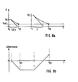
- the evaluation circuit according to FIG. 3 requires significantly less effort than that in FIG. 1.
- the integrator was dispensed with. Instead, the first sample and hold element with the storage capacitor 5 is connected directly to the first input 13 of the compensator 14.
- the storage capacitor 7 of the second sample and hold element which, as in FIG. 1, is directly coupled to the second input 15 of the comparator, is bridged here by a resistor R 2 , which bears the reference number 19.
- the resistor 19 is switched so that it discharges the storage capacitor 7, with the time constant
- the temperature compensation of the heating voltage also takes place here.
- the influence of the time constant T as described above, can be derived from the reference voltage ratio be compensated.
- the evaluation circuit according to FIG. 3 becomes the quotient formed and not as with the evaluation circuit 0 according to FIG. 1 .
- the time t 02 is formed in logarithmic and not in a linear dependence from the voltage ratio mentioned with the evaluation circuit according to FIG. 3. Approximately, however, conditions similar to those in the circuit arrangement according to FIG. 1 result, since can be expressed as
- the linearity deviation is less than 5%.
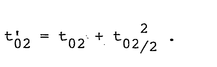
- the linearity can be improved to 1.5% by adding a quadratic link;
- the linearization can also take place instead by adapting the characteristic of the resistance probe.
- the storage capacitor 7 is thus discharged via the resistor 19 and the resistance probe 1 from the time t 01 , when the constant current is switched off with the controlled switch 3. Conversely, the storage capacitor 7 is also charged beforehand via the resistor 12, as a result of which higher-frequency interference can be suppressed.
- the switched off constant current source does not generate any significant residual current that leads to an offset voltage at the probe.
- the feed lines to the measuring probe are relatively short in order not to pick up any major disturbances.
- the time constant T is small compared to the time constant with which the temperature at the resistance probe changes.
- the up-down counter 23 counts upwards controlled by the sequence controller 25.
- a reference voltage ratio can be formed in the manner already indicated, namely as a time difference t 4 - t 3 analogous to the time difference described above
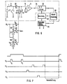
- the circuit part in FIG. 6 is provided, which is fed with the voltage U 2 . It is a voltage divider with the divider resistor 26 and the adjustable divider resistor 27.
- the voltage U min can be tapped at the common connection point between the two divider resistors.
- the voltage U 2 is sampled using a sampling switch 28 or S 2 .
- the voltage U min is queried with the sampling switch 28 1 or S 3 .
- the switches are actuated by the sequence controller 25 following the switches 3 and S 1 , see the pulse diagram in FIG. 7.
- the discharge of the capacitor 21 until the reference voltage U ref is reached then results in the following times:
- a further variable can then be formed to form a warning signal when a warning level is exceeded or fallen below.
- another voltage divider is used, which in FIG. 6 forms the voltage U W with the fixed divider resistor 30 and the adjustable divider resistor 31 from the voltage U 2 , S 4 can be scanned and charges the storage capacitor 21.
- the following relationship is finally formed, which signals the exceeding or falling below a warning level:
- the warning level min does not change if the output signal for the minimum fill level is adjusted.
- the function block 33 controls the function block 34 with output signal generators for level-proportional signals such as frequency, duty cycle, current or voltage by means of a digital-to-analog converter. Furthermore, the output signal generator forms level warning signals e.g. for reserve warning in motor vehicles.
Abstract
In einer Schaltungsanordnung zur elektrothermischen, Umgebungstemperatur-kompensierten Füllstandmessung mit einer geschalteten Konstantstromquelle (2) an einer Widerstandssonde (1) wird mit einem Vergleicher (Komparator 14) eine aus einer Anfangsspannung U0 an der Widerstandssonde zu Beginn einer Aufheizzeit gebildete erste Größe mit einer aus einer Aufheizspannung U1 zum Ende einer Aufheizzeit gebildeten zweiten Größe verglichen. Eine dieser beiden Größen, hier die erste Größe, wird entsprechend einem Zeitintegral gebildet und dem Vergleich mit der anderen Größe zugrunde gelegt. Zur Integralbildung sind ein Widerstand (10) und ein Kondensator (9) Bestandteile eines Integrators, dessen Eingang über ein erstes Abtast- und Halteglied (4,5) für die Anfangsspannung U0 mit der Widerstandssonde (1) gekoppelt werden kann. Der Ausgang des Integrators steht mit einem ersten Eingang (13) eines Komparators (14) in Verbindung. Der zweite Eingang (15) des Komparators ist über ein zweites Abtast- und Halteglied (6, 7) direkt, d. h. nicht über einen Inverter für die Aufheizspannung U1 mit der Widerstandssonde (1) koppelbar. Mit dem Ausgang des Komparators ist ein voreinstellbarer Rückwärtszähler (17) zum Erfassen der Zeit zwischen der Betätigung des zweiten Abtast- und Halteglieds und dem Umschalten des Komparators angeschlossen.In a circuit arrangement for electrothermal, ambient temperature-compensated level measurement with a switched constant current source (2) on a resistance probe (1), a comparator (comparator 14) is used to generate a first variable from an initial voltage U0 at the resistance probe at the beginning of a heating-up time Heating voltage U1 compared to the second quantity formed at the end of a heating time. One of these two quantities, here the first quantity, is formed according to a time integral and is used as a basis for comparison with the other quantity. For integral formation, a resistor (10) and a capacitor (9) are components of an integrator, the input of which can be coupled to the resistance probe (1) via a first sample and hold element (4, 5) for the initial voltage U0. The output of the integrator is connected to a first input (13) of a comparator (14). The second input (15) of the comparator is direct via a second sample and hold element (6, 7). H. cannot be coupled to the resistance probe (1) via an inverter for the heating voltage U1. A presettable down counter (17) is connected to the output of the comparator for recording the time between the actuation of the second sample and hold element and the switching of the comparator.
Description
Die Erfindung betrifft eine Schaltungsanordnung zur elektrothermischen, Umgebungstemperatur-kompensierten Füllstandmessung nach dem Oberbegriff des Anspruchs 1.The invention relates to a circuit arrangement for electrothermal, ambient temperature-compensated level measurement according to the preamble of
Bei einer derartigen bekannten Schaltungsanordnung wird die Widerstandssonde mit jedem Meßbeginn (Beginn einer Meßperiode) an die Konstantstromquelle gelegt, die während der Aufheizzeit von einer Ablaufsteuerung (Verzögerungsschaltung) betätigt ist. Letztere steht mit dem Vergleicher in Verbindung. Der Vergleicher ist einerseits mit einem an die Widerstands-' sonde angeschlossenen Inverter und einem dazu parallelgeschalteten Widerstandskondensatorglied verbunden, und zwar so, daß der Vergleicher ein Ausgangssignal an eine Überwachungsvorrichtung abgibt, sobald die über das Widerstandskondensatorglied abfallende Spannung gleich derjenigen des Inverters ist (DE-OS 27 40 289). Das Meßprinzip beruht darauf, daß die Widerstandsänderung der Widerstandssonde, die mehr oder weniger von dem zu messenden Fluid umgeben ist, gemessen wird, die sich am Ende einer Aufheizzeit durch einen Konstantstrom einstellt. Üblicherweise wird dabei die Differenz der Spannung U1 am Ende der Aufheizzeit gegenüber einer Anfangsspannung Uo zu deren Beginn erfaßt. Damit das Ergebnis dieser Messung unabhängig von der Umgebungstemperatur ist, wird nach diesem Stand der Technik im einzelnen vorgesehen: Der Inverter liefert zum Zeitpunkt des Einschaltens der Widerstandssonde eine Spannung V-U0, die den Kondensator des Widerstandskondensatorglieds auflädt. Dieser entlädt sich dann nach einer bekannten Gesetzmäßigkeit die durch den Widerstandswert und die Kapazität bestimmt ist. Wenn sich im weiteren Verlauf der Aufheizzeit die Widerstandssonde erwärmt, nimmt die Spannun U zu und der Inverter liefert eine Spannung der Form V-U, die von der Eintauch- tiefe der Widerstandssonde abhängig ist. Mit dem Vergleicher wird der Zeitpunkt erfaßt, zu dem der Spannungsverlauf des Kondensators (Aufladungskurve), der als Gerade darstellbar ist, die Kurve der invertierten Spannung V-U schneidet. Zu einem durch die Ablaufsteuerung bestimmten Zeitpunkt wird der Vergleicher so gesteuert, daß ein Vergleich zwischen dem Wert der invertierten Spannung V-U0 an den Anschlüssen des Widerstandskondensatorglieds und dem Wert der an dem Inverter liegenden Spannung durchgeführt wird. Eine mit dem Ausgang des Vergleichers verbundene Überwachungsvorrichtung kann hierbei bei Überschreiten eines vorgebbaren Schwellwerts einen Alarm auslösen.-Generell kann nach diesem Stand der Technik auch das Niveau einer Flüssigkeit angezeigt werden, in welches die Widerstandssonde eintaucht, und zwar mit numerischen oder analogen Anzeigeinstrumenten. - Diese Schaltungsanordnung ist insbesondere wegen des vorgesehenen Inverters verhältnismäßig aufwendig. Darüber hinaus ist nicht ersichtlich, wie diese Schaltungsanordnung zur Bildung numerischer Anzeigewerte in einen Analogdigitalumsetzer integriert werden kann.In such a known circuit arrangement, the resistance probe is connected to the constant current source with each start of measurement (start of a measurement period), which is actuated by a sequence control (delay circuit) during the heating-up time. The latter is related to the comparator. The comparator is connected on the one hand to an inverter connected to the resistance probe and to a resistance capacitor element connected in parallel, in such a way that the comparator outputs an output signal to a monitoring device as soon as the voltage drop across the resistance capacitor element is equal to that of the inverter (DE-
Weiterhin ist eine Schaltungsanordnung ähnlich der gattungsgemäßen Art zur elektrothermischen Füllstandsmessung mit einer durch einen Konstantstrom beheizten Widerstandssonde, mit einer eine von dem Eintauchzustand der Widerstandssonde abhängigen Meßspannung auswertenden Auswertschaltung, in die zur Temperaturkompensation außerdem eine Kombinationsspannung einspeisbar ist, vorgeschlagen worden, bei der von der Widerstandssonde zu Beginn der Aufheizzeit die Kompensationsspannung abfragbar und speicherbar ist und am Ende der Aufheizzeit die Meßspannung abfragbar ist (Patentanmeldung P 33 37 779.0 ). Zur Temperaturkompensation ist die Auswertschaltung zur Bildung des Quotienten aus Meßspannung und Kompensationsspannung während jeder Abtastperiode eingerichtet. Die Meßspannung und die Kompensationsspannung können nach diesem Prinzip auch in einen Analogdigitalumsetzer eingespeist werden, mit dessen Ausgang digitale Speicher und eine digitale Rechenschaltung zur Quotientenbildung in Verbindung stehen. - Diese Schaltungsanordung ist wegen der Mittel zur Quotientenbildung verhältnismäßig aufwendig. Dies gilt bei einer Ausführung der Auswertschaltung in Analogtechnik zur Bildung des Quotienten und besonders in der Ausfürhung in Digitaltechnik, da hier der Analogdigitalumsetzer zunächst die Meßspannung und die Kompensationsspannung umzusetzen hat, bevor deren digitalisierte Größen weiter ausgewertet werden können.Furthermore, a circuit arrangement similar to the generic type for electrothermal level measurement with a resistance probe heated by a constant current, with an evaluation circuit evaluating a measurement voltage dependent on the immersion state of the resistance probe, into which a combination voltage can also be fed in for temperature compensation, has been proposed, in which the resistance probe at the beginning of the heating-up period the compensation voltage can be queried and stored and at the end of the heating-up period the measuring voltage can be queried (
Der vorliegenden Erfindung liegt daher die Aufgabe zugrunde, eine Schaltungsanordnung der eingangs genannten Gattung so weiterzubilden, daß sie bei einfachem Aufbau und hoher Genauigkeit zur Abgabe digitalisierter Füllstandswerte geeignet ist und hierzu besonders leicht in einen entsprechenden Umsetzer integrierbar ist.The present invention is therefore based on the object of developing a circuit arrangement of the type mentioned at the outset in such a way that it is suitable for outputting digitized fill level values with a simple structure and high accuracy and for this purpose it is particularly easy to integrate into a corresponding converter.
Diese Aufgabe wird in einer ersten Variante nach der in dem Anspruch 1 gekennzeichneten Erfindung gelöst.This object is achieved in a first variant according to the invention characterized in
Nach dieser Variante erfolgt die Umgebungstemperaturkompensation bzw. die Normierung der an der Widerstandssonde erfaßten Temperaturdifferenz zwischen Aufheizspannung U1 und Anfangsspannung U0 bezogen auf die Anfangsspannung U0 durch Vergleich der erfaßten Aufheizspannung zu der zuvor erfaßten und anschließend aufintegrierten Anfangsspannung. Der Temperaturgang der Widerstandssonde wird dabei durch eine Quotientenbildung kompensiert.According to this variant, the ambient temperature compensation or the normalization of the temperature difference detected on the resistance probe between heating voltage U 1 and starting voltage U 0 is based on the starting voltage U 0 by comparing the detected heating voltage to the previously detected and subsequently integrated initial voltage. The temperature response of the resistance probe is compensated for by forming a quotient.
Der diesen Vergleich durchführende Komparator kann nach Anspruch 3 zweckmäßig zum Bestandteil eines nach dem Sägezahnverfahren arbeitenden Analogdigitalumsetzers gemacht werden, der mit einer Zählfrequenz die Zeit digitalisiert, die zwischen dem Erreichen der Aufheizspannung durch die integrierte Anfangsspannung einerseits und dem Beginn des Vergleichs liegt.The comparator performing this comparison can expediently be made as part of an analog-digital converter which operates according to the sawtooth method and which digitizes with a counting frequency the time between the reaching of the heating voltage by the integrated initial voltage on the one hand and the beginning of the comparison.
Der Integrator kann dabei wenig aufwendig und genau arbeitend mit einem Operationsverstärker und einem Kondensator' in dessen Rückkopplungszweig aufgebaut sein.The integrator can be constructed with little effort and precise work with an operational amplifier and a capacitor in its feedback branch.
Es wird noch bemerkt, daß die Genauigkeit des Meßprinzips nach der ersten Variante durch Anwendung eines Umsetzers, der nach dem Zwei-Rampenverfahren arbeitet (Dual-Slope-Umsetzer mit Nullpunktkorrektur) noch steigern läßt.It is also noted that the accuracy of the measuring principle according to the first variant can be increased by using a converter which works according to the two-ramp method (dual-slope converter with zero point correction).
Eine zweite Variante zur erfindungsgemäßen Lösung der Aufgabenstellung ist in dem kennzeichnenden Teil des Anspruchs 4 angegeben.A second variant for solving the problem according to the invention is specified in the characterizing part of claim 4.
Hier efolgt mit einfachsten Mitteln eine Quotientenbildung bzw. Normierung auf die Anfangsspannung U0. Der normierte Wert wird wie bei der ersten Variante als Zeit zwischen Betätigung des zweiten Abtast- und Halteglieds bzw. Abtasten der Aufheizspannung und Umschalten des Komparators erfaßt. Auch diese Zeit kann wie in der ersten Variante nach dem Sägezahnverfahren in einem integrierten Analogdigitalumsetzer in einen digitalen Niveauwert umgesetzt werden. Der Vergleich zwischen der Anfangsspannung und der entsprechend dem Widerstand und dem Kondensator zeitvariablen abgetasteten Aufheizspannung wird hier besonders wenig aufwendig durchgeführt: An den Eingängen des hierzu vorgesehenen Komparators liegen direkt beide Abtast- und Halteglieder sowie der den Kondensator des zweiten Halteglieds entladende Widerstand. - Allerdings beinhaltet hier die durch Umschalten des Komparators markierte Zeit nicht proportional die auf die Anfangsspannung normierte Differenz zwischen Aufheizspannung und Anfangsspannung, sondern einen logarithmischen Wert des Quotienten Aufheizspannung zu Anfangsspannung. Mit relativ kleinem Linearitätsfehler entspricht jedoch der Logarithmus dieses Quotienten dem Quotienten selbst. Die Linearitätsabweichung kann in vielen Fällen in Kauf genommen werden, da die Kennlinie der Widerstandssonde an den jeweiligen Meßort, insbesondere einen Kraftfahrzeugtank anzupassen ist.Here, the simplest means are used to form a quotient or normalize the starting voltage U 0 . As in the first variant, the normalized value is recorded as the time between actuation of the second sampling and holding element or sampling of the heating voltage and switching over of the comparator. As in the first variant, this time can also be converted into a digital level value using the sawtooth method in an integrated analog-digital converter. The comparison between the initial voltage and the heating voltage, which is sensed in a time-variable manner according to the resistance and the capacitor, is carried out particularly inexpensively here: Both sampling and holding elements and the resistor discharging the capacitor of the second holding element are located directly at the inputs of the comparator provided for this purpose. - However, the time marked by switching the comparator does not include the difference between the heating voltage and the starting voltage standardized to the starting voltage, but a logarithmic value of the quotient heating voltage to starting voltage. With a relatively small linearity error, however, the logarithm of this quotient corresponds to the quotient itself. The linearity deviation can be accepted in many cases, since the characteristic curve of the resistance probe has to be adapted to the respective measurement location, in particular a motor vehicle tank.
Höhere Anforderungen an die Linearität können aber auch nach der zweiten Schaltungsvariante gemäß Anspruch 5 durch Hinzunahme eines quadratischen Glieds der am Komparator ermittelten Zeitdauer erfüllt werden.However, higher demands on the linearity can also be met according to the second circuit variant according to
Unter bestimmten Bedingungen, auf die noch weiter unten eingegangen wird, kann die Schaltungsanordnung nach der zweiten Variante der Erfindung noch weiter durch die Maßnahmen nach Anspruch 6 vereinfacht werden. - Es entfällt hierbei also ein Abtastschalter und die zugehörige Steuerung.Under certain conditions, which will be discussed further below, the circuit arrangement according to the second variant of the invention can be further simplified by the measures according to claim 6. - There is therefore no need for a sampling switch and the associated control.
Zur Lösung der erfindungsgemäßen Aufgabe ist eine dritte Variante in dem kennzeichnenden Teil des Anspruchs 7 angegeben.To achieve the object of the invention, a third variant is specified in the characterizing part of claim 7.
Diese dritte Variante hat die zusätzlichen Vorteile, daß geringere Anforderungen an den Komparator und die Abtast- ! schalter zu stellen sind, d.h. entsprechend weniger aufwendige Elemente genügen. - In einem Komparator, dessen einer Eingang mit der durch ein Widerstandskondensatorglied entladenen Anfangsspannung und anschließend entladenen Aufheizspannung beaufschlagt wird, erfolgt ein Vergleich mit einer konstanten Referenzspannung. Der Komparator steuert hier einen Vorwarts-Rückwärts-Zähler, der einen Zählwert entsprechend dem Logarithmus aus dem Quotienten zwischen Aufheizspannung zu Anfangsspannung auszählt. - In den Zählwert gehen Schwankungen der Referenzspannung und der sogenannten Offset-Spannung des Komparators nicht ein, wenn diese Werte während einer Meßperiode sich nicht ändern.This third variant has the additional advantages that lower demands on the comparator and the sampling! switches must be set, i.e. correspondingly less complex elements are sufficient. In a comparator, the input of which is charged with the initial voltage discharged by a resistance capacitor element and then the discharged heating voltage, a comparison is made with a constant reference voltage. The comparator controls a forward-backward counter, which counts a count value according to the logarithm from the quotient between the heating voltage and the starting voltage. - Fluctuations in the reference voltage and the so-called offset voltage of the comparator are not included in the count value if these values do not change during a measuring period.
Der sonst in den Zählwert eingehende Einfluß der Zeitkonstante des Widerstandskondensatorglieds kann vorteilhaft nach Anspruch 8 eliminiert werden. Nach der Weiterbildung gemäß Anspruch 8 kann ein Ausgangssignal für minimalen Füllstand eingestellt werden.Otherwise the incoming count value in the influence of the time constant of the W iderstandskondensatorglieds can be advantageously eliminated
Gemäß Anspruch 9 kann die Schaltungsanordnung in der dritten Variante so ausgebaut werden, daß sie sich zur Abgabe eines Warnsignals bei Über- oder Unterschreiten eines Warnniveaus zusätzlich eignet.According to claim 9, the circuit arrangement in the third variant can be expanded so that it is additionally suitable for emitting a warning signal when a warning level is exceeded or fallen below.
Die Erfindung wird im folgenden anhand einer Zeichnung mit acht Figuren näher erläutert. Es zeigen:
Figur 1 eine Schaltungsanordnung zur elektrothermischen Füllstandmessung in einer ersten Variante;- Figur 2 Zeitabläufe hierin erfaßter Spannungen;
Figur 3 eine Schaltungsanordnung zur elektrothermischen Füllstandmessung in einer zweiten Ausführungsform;- Figur 4 Zeitabläufe der in der Schaltungsanordnung nach
Figur 3 erfaßten Spannungen; Figur 5 eine Variante der Schaltungsanordnung nach Figur 4;- Figur 6 eine Gesamt-Schaltungsanordnung zur elektrothermischen Füllstandmessung in einer dritten Variante;
- Figur 7 Zeitabläufe von Schalterstellungen in der Schaltungsanordnung nach Figur 6;
- Figur 8a in der Schaltungsanordnung nach Figur 6 erfaßte zeitvariable Spannungen und
- Figur 8b aus den Zeitabläufen gemäß Figur 8a abgeleitete Zählerstände eines Vorwärts-Rückwärts-Zählers in Figur 6.
- Figure 1 shows a circuit arrangement for electrothermal level measurement in a first variant;
- Figure 2 shows timings of voltages detected herein;
- Figure 3 shows a circuit arrangement for electrothermal level measurement in a second embodiment;
- FIG. 4 shows the time sequences of the voltages detected in the circuit arrangement according to FIG. 3;
- Figure 5 shows a variant of the circuit arrangement of Figure 4;
- Figure 6 shows an overall circuit arrangement for electrothermal level measurement in a third variant;
- FIG. 7 time sequences of switch positions in the circuit arrangement according to FIG. 6;
- Figure 8a in the circuit arrangement of Figure 6 detected time-variable voltages and
- FIG. 8b counter readings of an up-down counter in FIG. 6 derived from the time sequences according to FIG. 8a.
In Figur 1 ist eine erste Variante der Auswerteschaltung zur Auswertung des an einer Widerstandssonde 1 entstehenden Spannungsabfalls zur Niveaumessung dargestellt. Die Widerstandssonde wird von einer Konstantstromquelle 2 über einen gesteuerten Schalter 3 mit einem getakteten Konstantstrom beheizt. Der Schalter 3 wird ebenso wie weitere in Figur 1 gezeigte und nachstehend erläuterte Schalter durch eine nicht gezeichnete Ablaufsteuerung gesteuert.FIG. 1 shows a first variant of the evaluation circuit for evaluating the voltage drop occurring at a
An die Widerstandssonde sind ein erstes Abtast- und Halteglied bestehend aus einem Abtastschalter 4 und einem Speicherkondensator 5, sowie ein zweites Abtast- und Halteglied bestehend aus einem Abtastschalter 6 und einem Speicherkondensator 7,angeschlossen.A first scanning and holding element consisting of a scanning switch 4 and a are connected to the resistance
Das erste Abtast- und Halteglied 4, 5 ist an einen Eingang (+) eines Integrators angeschlossen, der aus einem Operationsverstärker 8, einem Kondensator 9 im Rückkopplungszweig und einem Widerstand 10 an einem Rückkopplungseingang (-) besteht. Parallel zu dem Kondensator 9 ist ein Rückstellschalter 11 dargestellt.The first sample and hold
Ein Ausgang 12 des Integrators ist an einen ersten Eingang 13 eines Komparators 14 gekoppelt. Der zweite Eingang 15 des Komparators steht mit dem Ausgang des zweiten Abtast-und Halteglieds 6, 7 in Verbindung.An
Der Ausgang des Komperators ist an einen Steuereingang 16 eines voreinstellbaren Rückwärtszählers 17 angeschlossen, in den über einen Zählfrequenzeingang 18 Zählfrequenzimpulse eingespeist werden.The output of the comparator is connected to a
Durch den mit der Ablaufsteuerung gesteuerten Betrieb der Auswerteschaltung nach Figur 1 laufen folgende Vorgänge in Meßperioden periodisch ab: Zunächst wird zu Beginn einer Aufheizzeit t0 der gesteuerte Schalter 3 geschlossen, wodurch an der Widerstandssonde die Anfangsspannung Uo abfällt, siehe Figur 2. Diese Anfangsspannung wird durch kurzzeitiges Schließen des Abtastschalters 4 in dem Speicherkondensator 5 gespeichert. Der Kondensator 9 des Integrators ist jedoch zunächst noch kurzgeschlossen, so daß die Integration noch nicht beginnt. Dies erfolgt erst, nachdem kurz vor Ende der Aufheizzeit zum Zeitpunkt t01 der zweite Abtastschalter 6 kurzzeitig geschlossen wird und die dann erreichte Aufheizspannung U1 in dem Speicherkondensator 7 gehalten wird. Jetzt wird der Rückstellschalter 11 geöffnet und die Spannung an dem Ausgang 12 des Integrators steigt deswegen linear mit einer Steigung an, die dem Wert der Ausgangsspannung Uo proportional ist. Die Anstiegsgeschwindigkeit bzw. die Integrationsgeschwindigkeit ergibt sich dabei aus der Zeitkonstanten![]()
![]()
Die Integration ab t01 verläuft so lange, bis zum Zeitpunkt t02 die aufintegrierte Anfangsspannung gleich der Aufheizspannung ist. Dann gilt (gerechnet ab t01):
Diese Zeit wird durch den voreinstellbaren Rückwärtszähler 17 gemessen, der während der Integrationszeit aus der Zählfrequenz f die Anzahl n zählt:![]()
![]()
Es ist aus der Formel für t02 ersichtlich, daß der Temperaturgang des Widerstandsfühlers durch die Quotientenbildung kompensiert ist.It can be seen from the formula for t 02 that the temperature response of the resistance sensor is compensated for by the quotient formation.
Zusätzlich kann durch Integration der voranstehend beschriebenen Art mit Referenzspannungen U'0, U'1 und aus deren Differenz ΔU' ein Referenzspannungsverhältnis ![]()
![]()
![]()
![]()
![]()
![]()
Wenn mit der Zählfrequenz f auch der Meßablauf gesteuert werden soll, ist für die Zählfrequenz eine Genauigkeit von < 1 % für typische Anwendungsfälle zu fordern.If the measuring sequence is also to be controlled with the counting frequency f, an accuracy of <1% for typical applications is required for the counting frequency.
Zu Figur 2 wird noch vermerkt, daß dort der Spannungsverlauf an der Widerstandssonde mit einer unterbrochenen Linie dargestellt ist.Regarding FIG. 2, it is also noted that the voltage curve on the resistance probe is shown with a broken line.
In der Variante der Auswertschaltung nach Figur 3 sind ebenso wie in den Figuren 5 und 6 gleiche Elemente wie in Figur 1 mit übereinstimmenden Bezugszeichen versehen.In the variant of the evaluation circuit according to FIG. 3, like in FIGS. 5 and 6, the same elements as in FIG. 1 are provided with the same reference numerals.
Die Auswerteschaltung gemäß Figur 3 kommt gegenüber derjenigen in Figur 1 mit deutlich verringertem Aufwand aus. Insbesondere wurde auf den Integrator verzichtet. Statt dessen ist das erste Abtast- und Halteglied mit dem Speicherkondensator 5 an den ersten Eingang 13 des Kompensators 14 unmittelbar angeschlossen. Der Speicherkondensator 7 des zweiten Abtast- und Halteglieds, der ebenso wie in Figur 1 unmittelbar mit dem zeiten Eingang 15 des Komparators gekoppelt ist, wird hier durch einen Widerstand R2 überbrückt, der das Bezugszeichen 19 trägt. Damit ist der Widerstand 19 so geschaltet, daß er den Speicherkondensator 7 entlädt, und zwar mit der ZeitkonstantenThe evaluation circuit according to FIG. 3 requires significantly less effort than that in FIG. 1. In particular, the integrator was dispensed with. Instead, the first sample and hold element with the
![]()

![]()
Die Zeit bis zu der diese sinkende Spannung den Wert der Anfangsspannung U0 erreicht ist dann
Durch diese Quotientenbildung erfolgt also auch hier die Temperaturkompensation der Aufheizspannung. Zusätzlich kann der Einfluß der Zeitkonstanten T, wie voranstehend be- schrieben, aus dem Referenzspannungsverhältnis ![]()
![]()
Der Auswerteschaltung nach Figur 3 wird allerdings der Quotient ![]()
![]()
![]()

![]()
![]()
![]()
Eingesetzt in die obengenannte logarithmische Beziehung für t02 ergibt sich dann, da ![]()
![]()

Wie erwähnt kann jedoch statt dessen auch die Linearisierung durch Kennlinienanpassung der Widerstandssonde erfolgen.As mentioned, however, the linearization can also take place instead by adapting the characteristic of the resistance probe.
Die Auswerteschaltung nach Figur 5 stellt eine Vereinfachung der Auswerteschaltung nach Figur 3 dar:
- Der die Ableitung der Spannung an dem Speicherkondensator 7 mit dem Wert C2 bewirkende Widerstand 19 mit dem Wert R2 ist hier nicht parallel zu dem Speicherkondensator 7 geschaltet, sondern ist anstelle des Abtastschalters 5 in die Schaltungsanordnung eingefügt.
- The
resistor 19 with the value R 2 , which leads to the derivation of the voltage on the storage capacitor 7 with the value C 2 , is not connected in parallel with the storage capacitor 7 here, but instead is inserted into the circuit arrangement instead of thesampling switch 5.
Somit wird der Speicherkondensator 7 ab dem Zeitpunkt t01, wenn der Konstantstrom mit dem gesteuerten Schalter 3 abgeschaltet wird, über den Widerstand 19 und die Widerstandssonde 1 entladen. Umgekehrt erfolgt zuvor die Aufladung des Speicherkondensators 7 ebenfalls über den Widerstand 12, wodurch höher-frequente Störungen unterdrückt werden können.The storage capacitor 7 is thus discharged via the
In der Schaltungsanordnung nach Figur 5 werden gegenüber derjenigen nach Figur 3 folgende Bedingungen eingehalten: Der Widerstandswert R2 des Widerstands 7 ist wesentlich größer als derjenige der Widerstandssonde, beispielsweise R2 = 100 kJ1 gegenüber dem Sondenwiderstand von etwa 15Ω. Die ausgeschaltete Konstantstromquelle erzeugt keinen wesentlichen Reststrom, der zu einer Offset-Spannung an der Sonde führt.In the circuit arrangement according to FIG. 5, the following conditions are maintained compared to those according to FIG. 3: The resistance value R 2 of the resistor 7 is essential larger than that of the resistance probe, for example R 2 = 100 kJ1 compared to the probe resistance of about 15Ω. The switched off constant current source does not generate any significant residual current that leads to an offset voltage at the probe.
Die Zuleitungen zu der Meßsonde sind relativ kurz, um keine großen Störungen aufzunehmen.The feed lines to the measuring probe are relatively short in order not to pick up any major disturbances.
Die Zeitkonstante T ist klein gegenüber der Zeitkonstanten, mit der sich die Temperatur an der Widerstandssonde ändert.The time constant T is small compared to the time constant with which the temperature at the resistance probe changes.
Die obengenannte Bedingung für die Zeitkonstante T kann durch Wahl des Speicherkondensators 7 mit dem Wert C2 = 100 nF zu dem genannten Widerstandswert von R2 erfüllt werden.The above-mentioned condition for the time constant T can be met by choosing the storage capacitor 7 with the value C 2 = 100 nF for the mentioned resistance value of R 2 .
Außerdem sind bei beiden Auswerteschaltungen nach den Figuren 3 und 5 folgende Zusatzforderungen für genaue Messungen zu erfüllen:
- 1. Die Offset-
Spannung des Komparators 14 muß klein sein. - 2. Die Restströme insbesondere über den Abtastschalter 4 müssen sehr klein sein.
- 1. The offset voltage of the
comparator 14 must be small. - 2. The residual currents, in particular via the sampling switch 4, must be very small.
In der Schaltungsanordnung nach Figur 6 (mit unterbrochener Linie umrahmter Teil) entfällt hingegen die erste Zusatzforderung und die zweite Zusatzforderung ist weniger scharf gestellt:
- In der Schaltungsanordnung nach Figur 6 ist nur noch ein einziges Abtast- und Halteglied
mit dem Abtastschalter 20und dem Speicherkondensator 21 vorgesehen. Er hat die Kapazität C. Parallel zu dem Speicherkondensatorist ein Widerstand 22 mit dem Widerstandswert R geschaltet. Dieses Abtast- und Halteglied liegt andem zweiten Eingang 15 desKomperators 14, dessen erster Eingang 13 mit einer konstante Referenzspannung Uref beaufschlagt wird. Der Ausgang des Komparators 14 steuert einen voreinstellbaren Rückwärts-Vorwärtszähler 23 über einen Steuereingang 24 ; der Vorwärts-Rückwärtszähler 23 steht zur Rückstellung mit einerAblaufsteuerung 25 in Verbindung, dieauch den Abtastschalter 20 undden gesteuerten Schalter 3 betätigt.
- In the circuit arrangement according to FIG. 6, only a single sample and hold element with the
sample switch 20 and thestorage capacitor 21 is provided. It has the capacitanceC. A resistor 22 with the resistance value R is connected in parallel with the storage capacitor. This sample and hold element is connected to thesecond input 15 of thecomparator 14, thefirst input 13 of which is constant Reference voltage U ref is applied. The output of thecomparator 14 controls a presettable down-up counter 23 via acontrol input 24; the up-down counter 23 is connected to asequence controller 25 for reset, which also operates thesampling switch 20 and the controlledswitch 3.
Die Funktion des bisher beschriebenen Schaltungsteils wird zunächst anhand der Figuren 7, Zeitverläufe I und S1 sowie anhand der Figuren 8a und 8b erläutert:
- Beim Einschalten des Konstantstroms
mit dem Schalter 3 wird zunächst die Anfangsspannung Uo inden Speicherkondensator 21 eingespeichert, in-dem der Abtastschalter 20 bzw. S1 kurzzeitig ab dem Zeitpunkt t0 betätigt wird. Danach entlädt sich der Speicherkondensator 21über den Widerstand 22 mit einer Zeitkonstanten T = R . Cbis die Kondensatorspannung andem Eingang 15 den Wert der Referenzspannung Uref andem Eingang 13 desKomparators 14 erreicht. Dies geschieht zu dem Zeitpunkt t01, siehe Figur 8a. Dann gilt
- When the constant current is switched on with the
switch 3, the initial voltage U o is first stored in thestorage capacitor 21 by briefly actuating thesampling switch 20 or S 1 from the time t0. Thereafter, thestorage capacitor 21 discharges through theresistor 22 with a time constant T = R. Cbis the capacitor voltage at theinput 15 reaches the value of the reference voltage U ref at theinput 13 of thecomparator 14. This takes place at time t 01 , see FIG. 8a. Then applies
Diese Zeit wird in dem Vorwärts-Rückwärtszähler 23, der zunächst auf Null zurückgestellt war, und in dieser Phase durch die Ablaufsteuerung 25 gesteuert rückwärts zählt, als Zahlenwert erfaßt, siehe Figur 8b. Kurz bevor der Konstantstrom durch den Schalter 3 abgeschaltet wird, erfolgt ein analoger Vorgang für die dann erreichte Aufheizspannung U1 durch erneutes kurzzeitiges Betätigen des Abtastschalters 20 bzw. S1 zum Zeitpunkt t1 (siehe Figur 7). Anschließend entlädt sich der Speicherkondensator 21 wiederum nach der bekannten Zeitfunktion über den Widerstand 22 bis zum Erreichen der Referenzspannung. Damit wird die Zeit gebildet
Während dieser Entladung zählt jedoch der Vorwärts-Rückwärts zähler 23 durch die Ablaufsteuerung 25 gesteuert vorwärts. Somit steht jetzt in dem Vorwärts-Rückwärtszähler 23 eine Zahl gleich der Differenz t02 - t01 = T · (ln 

Daraus ist ersichtlich, daß der Einfluß der Referenzspannung herausfällt ebenso derjenige einer Offset-Spannung, um die die Referenzspannung größer oder kleiner ist, wenn sich die genannten Spannungen während der Meßzeit von ca. 2 Sekunden nicht ändern.It can be seen from this that the influence of the reference voltage also drops out that of an offset voltage by which the reference voltage is greater or smaller if the voltages mentioned do not change during the measuring time of approximately 2 seconds.
Um den Einfluß der Zeitkonstanten T = R . C zu kompensieren, kann in der schon angedeuteten Weise ein Referenzspannungsverhältnis gebildet werden, und zwar als Zeitdifferenz t4 - t3 analog zu der oben beschriebenen Zeitdifferenz![]()
![]()
Hierzu ist der Schaltungsteil in Figur 6 vorgesehen, der mit der Spannung U2 gespeist wird. Es handelt sich um einen Spannungsteiler mit dem Teilerwiderstand 26 und dem einstellbaren Teilerwiderstand 27. An dem gemeinsamen Verbindungspunkt zwischen beiden Teilerwiderständen ist die Spannung Umin abgreifbar. Die Abtastung der Spannung U2 erfolgt mit einem Abtastschalter 28 bzw. S2.For this purpose, the circuit part in FIG. 6 is provided, which is fed with the voltage U 2 . It is a voltage divider with the
Die Spannung Umin wird mit dem Abtastschalter 281bzw. S3 abgefragt. Die Schalter werden durch die Ablaufsteuerung 25 im Anschluß an die Schalter 3 und S1 betätigt, siehe Impulsdiagramm Figur 7. Durch die Entladung des Kondensators 21 bis zum Erreichen der Referenzspannung Uref ergeben sich dann jeweils folgende Zeiten:

Daraus ergibt sich als Differenz und entsprechender Zählwert des Vorwärts-Rückwärtszählers 23:
Anschließend kann in dem Schaltungsteil "Verarbeitung" in Figur 6 mit dem Bezugszeichen 33 ablaufgesteuert folgender Quotient gebildet werden: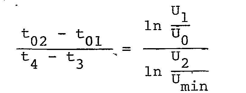
Damit entfällt der Einfluß von T und das Ausgangssignal für den minimalen Füllstand kann eingestellt werden.This eliminates the influence of T and the output signal for the minimum fill level can be set.
Zur Bildung eines Warnsignals beim Über- oder Unterschreiten eines Warnniveaus kann anschließend eine weitere Größe gebildet werden. Dazu dienen ein weiterer Spannungsteiler, der in Figur 6 mit dem festen Teilerwiderstand 30 und dem einstellbaren Teilerwiderstand 31 aus der Spannung U2 die Spannung UW bildet, die durch einen Abtastschalter 32 bzw. S4 abtastbar ist und den Speicherkondensator 21 lädt. Es wird durch Laden und Entladen des Speicherkondensators, durch Erfassen der Spannungsgleichheit mit der Referenzspannung an dem Komparator und entsprechendes Rückwärts-und Vorwärtszählen und Quotientenbildung analog zu den vorangehend beschriebenen Vorgängen schließlich folgende Beziehung gebildet, die das Über- oder Unterschreiten eines Warnniveaus signalisiert:
Durch die Normierung auf ln ![]()
![]()
Zu dem Impulsdiagramm gemäß Figur 7 wird noch erläutert, daß in dem Zeitrahmen "Verarbeitung" folgende Vorgänge in einem Funktionsblock 33 außer der voranstehend beschriebenen Normierung durch Quotientenbildung ablaufen: Kennlinienlinearisierung und gleitende Mittelwertbildung. Der Funktionsblock 33 steuert den Funktionsblock 34 mit Ausgangssignalerzeugern für füllstandsproportionale Signale wie Frequenz, Tastverhältnis, Strom oder Spannung mittels eines Digitalanalogumsetzers. Weiterhin bildet der Ausgangssignalerzeuger Niveauwarnsignale z.B. zur Reservewarnung in Kraftfahrzeugen.With regard to the pulse diagram according to FIG. 7, it is also explained that in the time frame “processing” the following processes take place in a
Claims (9)
dadurch gekennzeichnet ,
daß der Widerstand (10) und der Kondensator (9) Bestandteile eines Integrators (Operationsverstärker 8) sind, dessen Eingang über ein erstes Abtast- und Halte-(sample and hold)-Glied (4, 5) für die Anfangsspannung Uo mit der Widerstandssonde (1) koppelbar ist und dessen Ausgang mit einem ersten Eingang (13) eines Komparators (14) in Verbindung steht, daß der zweite Eingang (15) des Komparators (14) über ein zweites Abtast- und Halteglied (6, 7) direkt für die Aufheizspannung U1 mit der Widerstandssonde koppelbar ist und daß mit einem Ausgang des Komparators (14) Mittel (voreinstellbarer Rückwärtszähler) zum Erfassen der Zeit zwischen Betätigung des zweiten Abtast- und Halteglieds (6, 7) und dem Umschalten des Komparators (14) angeschlossen sind.1. Circuit arrangement for electrothermal, ambient temperature-compensated level measurement with a switched constant current source on a resistance probe, with a comparator that has a first variable formed from an initial voltage U 0 at the resistance probe at the beginning of a heating up period with a heating voltage U 1 at the end of a heating up period compares the second variable formed, the formation of at least one of the two variables taking place in accordance with a time function determined by a capacitor and a resistor,
characterized ,
that the resistor (10) and the capacitor (9) are components of an integrator (operational amplifier 8), the input of which via a first sample and hold (4, 5) element for the initial voltage U o with the Resistance probe (1) can be coupled and its output is connected to a first input (13) of a comparator (14) that the second input (15) of the comparator (14) directly via a second sample and hold element (6, 7) for the heating voltage U 1 can be coupled to the resistance probe and that with an output of the comparator (14) means (presettable down counter) for detecting the time between actuation of the second sample and hold element (6, 7) and switching of the comparator (14) are connected.
dadurch gekennzeichnet ,
daß der Integrator mit einem Operationsverstärker (8) gebildet ist, in dessen Rückkopplungszeig der Kondensator (9) angeordnet ist.2. Circuit arrangement according to claim 1,
characterized ,
that the integrator is formed with an operational amplifier (8), in the feedback view of which the capacitor (9) is arranged.
dadurch gekennzeichnet ,
daß der Komparator (14) Bestandteil eines nach dem Sägezahnverfahren arbeitenden Analogdigitalumsetzers ist, der einen voreinstellbaren, mit einer Zählfrequenz beaufschlagbaren, durch den Komparator (14) steuerbaren Rückwärtszähler (17) aufweist.3. Circuit arrangement according to claim 1 or 2,
characterized ,
that the comparator (14) is part of an analog-to-digital converter which operates according to the sawtooth method and has a presettable down counter (17) which can be loaded with a counting frequency and which can be controlled by the comparator (14).
dadurch gekennzeichnet ,
daß ein erster Eingang (13) eines Komparators (14) über das erste Abtast- und Halteglied (4, 5) für die Anfangsspannung U0 mit der Widerstandssonde (1) koppelbar ist, daß der Kondensator (7) Bestandteil eines zweiten Abtast- und Halteglieds (6, 7) für die Aufheizspannung U1 ist, daß zu dem Kondensator (7) der Widerstand (19), die Aufheizspannung U1 ableitend,parallelgeschaltet ist und daß mit einem Ausgang des Komparators (14) Mittel (voreinstellbarer Rückwärtszähler 17) zum Erfassen der Zeit zwischen Betätigung des zweiten Abtast- und Halteglieds und dem Umschalten des Komparators angeschlossen sind.4. Circuit arrangement for electrothermal, ambient temperature-compensated level measurement with a switched constant current source on a resistance probe, with a comparator that has a first variable formed from an initial voltage U o at the resistance probe at the beginning of a heating-up time and with a heating voltage U 1 at the end of a heating-up time compares the second variable formed, the formation of at least one of the two variables taking place in accordance with a time function determined by a capacitor and a resistor,
characterized ,
that a first input (13) of a comparator (14) via the first sample and hold element (4, 5) for the initial voltage U 0 can be coupled to the resistance probe (1), that the capacitor (7) is part of a second sample and Holding element (6, 7) for the heating voltage U 1 is that the resistor (19), which dissipates the heating voltage U 1 , is connected in parallel with the capacitor (7) and that means (presettable down counter 17) are connected to an output of the comparator (14) are connected to detect the time between actuation of the second sample and hold element and the switching of the comparator.
dadurch gekennzeichnet ,
daß zur Linearisierung der Füllstandmessung die Mittel zur Erfassung der Zeit t02 zwischen Entkoppeln des zweiten Abtast- und Halteglieds (6, 7) und dem Umschalten des Komparators (14) außerdem zum additiven Erfassen des Quadrats der Halbzeit nach der Beziehung t'02 = t02 +
characterized ,
that for linearizing the level measurement, the means for detecting the time t 02 between decoupling the second sample and hold element (6, 7) and switching the comparator (14) also for additively detecting the square of the half according to the relationship t '02 = t 02 +
dadurch gekennzeichnet ,
daß das zweite Abtast- und Halteglied (Abtastschalter) entfällt und statt dessen der Kondensator (Speicherkondensator 7) über den Widerstand (19) ständig mit der Widerstandssonde (1) in Verbindung steht.6. Circuit arrangement according to claim 4,
characterized ,
that the second sample and hold element (sample switch) is omitted and instead the capacitor (storage capacitor 7) via the resistor (19) is in constant communication with the resistance probe (1).
dadurch gekennzeichnet ,
daß ein erster Eingang (15) eines Komparators (14) an dem Kondensator (Speicherkondensator 21) sowohl für die Anfangsspannung U0 als auch für die Aufheizspannung U1 zu unterschiedlichen Zeitpunkten t0 und t11 mit der Widerstandssonde (1) über einen ersten Abtastschalter (20) koppelbar ist, daß zu dem Kondensator (Speicherkondensator 21) der die Spannung U0 bzw. U1 ableitende Widerstand (22) parallelgeschaltet ist, daß an einem zweiten Eingang (13) des Komparators (14) eine konstante Referenzspannung U ref liegt und daß der Ausgang des Komparators (14) an einem Steuereingang (24) eines rückstellbaren, mit einer Zählfrequenz beaufschlagbaren Vorwärts-Rückwärtszählers (23) angeschlossen ist, daß der Vorwärts-Rückwärtszähler während des Entladens (bis t01) des auf die Spannung Uo geladenen Kondensators bis zum Erreichen der Referenzspannung in einer ersten Richtung (vorwärts) zählt und anschließend während des Entladens (bis t12) des auf die Spannung U1 geladenen Kondensators bis zum Erreichen der Referenzspannung in einer entgegengesetzten Richtung (rückwärts) differenzbildend (t12 - t01) zählt.7. Circuit arrangement for electrothermal, ambient temperature-compensated level measurement with a switched constant current source on a resistance probe, with a comparator, which is a first variable formed from an initial voltage U 0 at the resistance probe at the beginning of a heating-up time and with a heating-up voltage U 1 increasing end of a heating-up time compares the second variable, the formation of at least one of the two variables taking place in accordance with a time function determined by a capacitor and a resistor,
characterized ,
that a first input (15) of a comparator (14) on the capacitor (storage capacitor 21) both for the initial voltage U 0 and for the heating voltage U 1 at different times t 0 and t 11 with the Resistance probe (1) can be coupled via a first sampling switch (20), that the resistor (22) which discharges the voltage U 0 or U 1 is connected in parallel to the capacitor (storage capacitor 21), that at a second input (13) of the comparator ( 14) there is a constant reference voltage U ref and that the output of the comparator (14) is connected to a control input (24) of a resettable up-down counter (23) which can be loaded with a counting frequency, that the up-down counter during unloading (up to t 01 ) of the capacitor charged to the voltage U o counts in a first direction (upward) until the reference voltage is reached and then during the discharge (to t 12 ) of the capacitor charged to the voltage U 1 until the reference voltage is reached in an opposite direction (backwards) forming a difference (t 12 - t 01 ) counts.
dadurch gekennzeichnet ,
daß das Ausgangssignal für den minimalen Füllstand an einen mit einer festen Spannung U2 gespeisten Spannungsteiler (26, 27) einstellbar ist, daß ein zweiter Abtastschalter (28) den Kondensator (Speicherkondensator 21) mit der minimalen Spannung Umin koppelt und ein dritter Abtastschalter (32) den Kondensator mit der festen, höheren Spannung U2 koppelt, daß der Vorwärts-Rückwärts- zähler (23) im Anschluß an die Differenzbildung t12 - t01 und Rückstellung während des Entladens t3 des auf die Spannung Umin geladenen Kondensators bis zum Erreichen der Referenzspannung Uref in einer ersten Richtung zählt und anschließend während des Entladens t4 des auf die Spannung U2 geladenen Kondensators bis zum Erreichen der Referenzspannung in einer entgegengesetzten Richtung differenzbildend t4 - t3 zählt, und daß der jeweilige Zählerstand auf Mittel zur Quotientenbildung (Verarbeitung 33,

characterized ,
that the output signal for the minimum fill level can be set on a voltage divider (26, 27) fed with a fixed voltage U 2 , that a second sampling switch (28) couples the capacitor (storage capacitor 21) with the minimum voltage U min and a third sampling switch ( 32) couples the capacitor with the fixed, higher voltage U 2 , that the up-down counter (23) following the formation of the difference t 12 - t 01 and resetting during the discharge t 3 of the capacitor charged to the voltage U min to counts to reach the reference voltage U ref in a first direction and then during the discharge t 4 of the capacitor charged to the voltage U 2 until the Reference voltage counts in an opposite direction to form a difference t 4 - t 3 , and that the respective counter reading is based on means for forming the quotient (processing 33,
dadurch gekennzeichnet,
daß ein weiterer Spannungsteiler (30, 31) an der festen Spannung U2 auf eine Warnspannung UW zum Auslösen einer Warnfunktion abgleichbar ist, daß nach Bildung der Differenzen t12 t01 und t4 - t3 der Spannungsteiler (30, 31) über einen vierten Abtastschalter (32) mit der Warnspannung UW zur Bildung der Differenz (t5 - t 3) beaufschlagbar ist und daß die Mittel zur Quotientenbildung (Verarbeitung 33) zusätzlich zur Bildung des Quotienten

characterized,
that a further voltage divider (30, 31) at the fixed voltage U 2 can be compared to a warning voltage U W for triggering a warning function, that after formation of the differences t 12 t 01 and t 4 - t 3 the voltage divider (30, 31) via a fourth sampling switch (32) can be supplied with the warning voltage U W to form the difference (t 5 - t 3 ) and that the means for forming the quotient (processing 33) in addition to forming the quotient
Applications Claiming Priority (2)
| Application Number | Priority Date | Filing Date | Title |
|---|---|---|---|
| DE3408824 | 1984-03-10 | ||
| DE19843408824 DE3408824A1 (en) | 1984-03-10 | 1984-03-10 | CIRCUIT ARRANGEMENT FOR ELECTROTHERMIC, AMBIENT TEMPERATURE COMPENSATED LEVEL MEASUREMENT |
Publications (2)
| Publication Number | Publication Date |
|---|---|
| EP0154716A1 true EP0154716A1 (en) | 1985-09-18 |
| EP0154716B1 EP0154716B1 (en) | 1988-06-29 |
Family
ID=6230108
Family Applications (1)
| Application Number | Title | Priority Date | Filing Date |
|---|---|---|---|
| EP84116136A Expired EP0154716B1 (en) | 1984-03-10 | 1984-12-21 | Circuit for electrothermal level measurement with ambient temperature compensation |
Country Status (4)
| Country | Link |
|---|---|
| US (1) | US4633491A (en) |
| EP (1) | EP0154716B1 (en) |
| JP (1) | JPS60207008A (en) |
| DE (2) | DE3408824A1 (en) |
Cited By (2)
| Publication number | Priority date | Publication date | Assignee | Title |
|---|---|---|---|---|
| DE3538181A1 (en) * | 1985-10-26 | 1987-04-30 | Messer Griesheim Gmbh | DEVICE FOR AUTOMATICALLY LIMITING THE LEVEL OF CRYOGENIC LIQUIDS |
| FR2681136A1 (en) * | 1991-09-05 | 1993-03-12 | Sagem | Method and circuit for monitoring the level of a liquid in a casing (sump) |
Families Citing this family (17)
| Publication number | Priority date | Publication date | Assignee | Title |
|---|---|---|---|---|
| FR2599835B1 (en) * | 1986-06-04 | 1988-08-26 | Bendix Electronics Sa | METHOD AND DEVICE FOR MEASURING THE LEVEL OF THE FREE SURFACE OF A LIQUID |
| JPH0342527U (en) * | 1989-09-01 | 1991-04-22 | ||
| JP2820530B2 (en) * | 1989-09-28 | 1998-11-05 | エンドレス ウント ハウザー ゲゼルシャフト ミット ベシュレンクテル ハフツング ウント コンパニー | Device for processing sensor signals |
| DE3932479A1 (en) * | 1989-09-28 | 1991-04-11 | Endress Hauser Gmbh Co | Sensor signal processing arrangement - adjusts transfer function coefficients to match measure sensor characteristics, correct various noise sources |
| US5111692A (en) * | 1990-03-27 | 1992-05-12 | Fluid Components, Inc. | Temperature compensated liquid level and fluid flow sensor |
| US5321633A (en) * | 1990-04-10 | 1994-06-14 | Yazaki Corporation | Heat radiating type liquid level sensing system and the method therefor |
| DE4016970A1 (en) * | 1990-05-25 | 1991-11-28 | Vdo Schindling | Container liquid level measurement - using electrothermal sensor with sensor resistance subjected to constant voltage at intervals, measurement of time |
| JP2548252Y2 (en) * | 1990-10-15 | 1997-09-17 | 株式会社カンセイ | Liquid level detector |
| JP2518169B2 (en) * | 1991-04-09 | 1996-07-24 | 株式会社村田製作所 | Liquid level detector |
| US5228340A (en) * | 1991-05-01 | 1993-07-20 | Yazaki Corporation | Method and apparatus for heat radiating type level sensor measurement of liquid level |
| US5291534A (en) * | 1991-06-22 | 1994-03-01 | Toyoda Koki Kabushiki Kaisha | Capacitive sensing device |
| DE4232043A1 (en) * | 1992-09-24 | 1994-03-31 | Siemens Ag | Process and appts. for continuous monitoring of fluid level - within a container such as the coolant level within a nuclear reactor |
| JP3208742B2 (en) * | 1992-11-13 | 2001-09-17 | 株式会社鷹山 | Memory device |
| DE19754126A1 (en) * | 1997-12-05 | 1999-06-17 | Siemens Ag | Circuit arrangement for controlling an electrical drive unit |
| JP4359843B2 (en) * | 2004-10-14 | 2009-11-11 | 横河電機株式会社 | Output circuit |
| JP5701528B2 (en) * | 2010-07-16 | 2015-04-15 | オリンパス株式会社 | Biological state quantity measuring device |
| JP5583153B2 (en) * | 2012-01-26 | 2014-09-03 | 株式会社東芝 | Liquid level detection device and method |
Citations (4)
| Publication number | Priority date | Publication date | Assignee | Title |
|---|---|---|---|---|
| DE2946585A1 (en) * | 1979-11-19 | 1981-05-27 | Vdo Adolf Schindling Ag, 6000 Frankfurt | DEVICE FOR ELECTRICALLY MONITORING THE LEVEL OF A LIQUID CONTAINED IN A CONTAINER |
| DE2740289B2 (en) * | 1976-10-06 | 1981-06-04 | Jaeger, Levallois-Perret, Hauts-de-Seine | Device for monitoring the level of a liquid contained in a container |
| US4356728A (en) * | 1979-05-21 | 1982-11-02 | E.D. Veglia | Device for measuring the level of a liquid |
| DE3133421A1 (en) * | 1981-08-24 | 1983-03-10 | Vdo Adolf Schindling Ag, 6000 Frankfurt | DEVICE FOR ELECTRICALLY MONITORING THE LEVEL OF A LIQUID CONTAINED IN A CONTAINER |
Family Cites Families (4)
| Publication number | Priority date | Publication date | Assignee | Title |
|---|---|---|---|---|
| DE2510356C2 (en) * | 1975-03-10 | 1984-03-15 | Siemens AG, 1000 Berlin und 8000 München | Device for monitoring the liquid level in a container |
| DE2607187C3 (en) * | 1976-02-23 | 1986-07-10 | Krautkrämer GmbH, 5000 Köln | Method for measuring the time interval between two electrical pulses |
| US4397031A (en) * | 1980-12-04 | 1983-08-02 | Weber Paul A | Time delay computer |
| FR2514134A2 (en) * | 1981-10-07 | 1983-04-08 | Jaeger | IMPROVEMENTS IN LIQUID LEVEL CONTROL DEVICES CONTAINED IN A RESERVOIR |
-
1984
- 1984-03-10 DE DE19843408824 patent/DE3408824A1/en not_active Withdrawn
- 1984-12-21 DE DE8484116136T patent/DE3472451D1/en not_active Expired
- 1984-12-21 EP EP84116136A patent/EP0154716B1/en not_active Expired
-
1985
- 1985-03-11 JP JP60046715A patent/JPS60207008A/en active Pending
- 1985-03-11 US US06/710,168 patent/US4633491A/en not_active Expired - Fee Related
Patent Citations (4)
| Publication number | Priority date | Publication date | Assignee | Title |
|---|---|---|---|---|
| DE2740289B2 (en) * | 1976-10-06 | 1981-06-04 | Jaeger, Levallois-Perret, Hauts-de-Seine | Device for monitoring the level of a liquid contained in a container |
| US4356728A (en) * | 1979-05-21 | 1982-11-02 | E.D. Veglia | Device for measuring the level of a liquid |
| DE2946585A1 (en) * | 1979-11-19 | 1981-05-27 | Vdo Adolf Schindling Ag, 6000 Frankfurt | DEVICE FOR ELECTRICALLY MONITORING THE LEVEL OF A LIQUID CONTAINED IN A CONTAINER |
| DE3133421A1 (en) * | 1981-08-24 | 1983-03-10 | Vdo Adolf Schindling Ag, 6000 Frankfurt | DEVICE FOR ELECTRICALLY MONITORING THE LEVEL OF A LIQUID CONTAINED IN A CONTAINER |
Cited By (2)
| Publication number | Priority date | Publication date | Assignee | Title |
|---|---|---|---|---|
| DE3538181A1 (en) * | 1985-10-26 | 1987-04-30 | Messer Griesheim Gmbh | DEVICE FOR AUTOMATICALLY LIMITING THE LEVEL OF CRYOGENIC LIQUIDS |
| FR2681136A1 (en) * | 1991-09-05 | 1993-03-12 | Sagem | Method and circuit for monitoring the level of a liquid in a casing (sump) |
Also Published As
| Publication number | Publication date |
|---|---|
| DE3472451D1 (en) | 1988-08-04 |
| JPS60207008A (en) | 1985-10-18 |
| US4633491A (en) | 1986-12-30 |
| DE3408824A1 (en) | 1985-09-12 |
| EP0154716B1 (en) | 1988-06-29 |
Similar Documents
| Publication | Publication Date | Title |
|---|---|---|
| EP0154716B1 (en) | Circuit for electrothermal level measurement with ambient temperature compensation | |
| EP0219725B1 (en) | Method of compensating interference voltages in the electrode circuit in magnetic-inductive flow measurement | |
| EP0139874B1 (en) | Circuit for thermo-electrical level measurement | |
| DE2740289C3 (en) | Device for monitoring the level of a liquid contained in a container | |
| DE2364517C2 (en) | Voltage / frequency converter | |
| DE3905824C2 (en) | ||
| EP0166034B1 (en) | Method and arrangement for electrothermal, ambient temperature compensated level measurement | |
| DE10333154A1 (en) | Method and circuit arrangement for evaluating a measuring capacity | |
| DE3037340A1 (en) | DRIVER FOR HEAT WIRE AIR FLOW METER | |
| EP0173833A2 (en) | Circuit and process to measure and to digitize a resistor | |
| EP0376024B1 (en) | Process and device for correcting a signal-processing circuit with respect to deviations from its elements due to manufacturing tolerances | |
| EP0250028B1 (en) | Circuit device for compensation of temperature dependent and temperature independent drifts of a capacitive sensor | |
| EP0927351B1 (en) | Air quality measuring device | |
| DE2547725B2 (en) | Method for analog-digital conversion of a direct voltage and circuit arrangement for carrying out the method | |
| DE4241702A1 (en) | Analogue=to=digital converter for electric motor speed control - counts clock pulses produced during period of PWM signal obtd. from error comparison with triangular wave | |
| EP0285047A2 (en) | Circuit for shaping a measure signal into a square wave signal | |
| DE4101819A1 (en) | MEASURING DEVICE FOR ELECTRICALLY MEASURING A RESISTANCE AND RELATED MEASURING METHOD | |
| DE4401949C1 (en) | Device for the multiplicative correction of an electric measurement signal | |
| EP0561054A1 (en) | Apparatus and procedure for measuring the time-constant of an electrical displacement transducer | |
| DE2460079B2 (en) | Method for determining the position of the loop of a potentiometer and circuit arrangement for carrying out the method | |
| DE3915880C2 (en) | ||
| DE102022201923B3 (en) | Method and circuit arrangement for determining an inductance of a measuring coil and use therefor | |
| DE2839123C2 (en) | Voltage-frequency converter | |
| EP0129132A1 (en) | Measuring device to detect a temperature difference | |
| DE4229539A1 (en) | Duty ratio measurement circuit for IC engine signal having different phases - has first counter for repetitively counting through range and second counter for counting number of cycled ranges, and counts out end value of second counter when phase of signal changes to obtain final result |
Legal Events
| Date | Code | Title | Description |
|---|---|---|---|
| PUAI | Public reference made under article 153(3) epc to a published international application that has entered the european phase |
Free format text: ORIGINAL CODE: 0009012 |
|
| AK | Designated contracting states |
Designated state(s): DE FR GB IT NL SE |
|
| 17P | Request for examination filed |
Effective date: 19851007 |
|
| 17Q | First examination report despatched |
Effective date: 19870219 |
|
| GRAA | (expected) grant |
Free format text: ORIGINAL CODE: 0009210 |
|
| AK | Designated contracting states |
Kind code of ref document: B1 Designated state(s): DE FR GB IT NL SE |
|
| GBT | Gb: translation of ep patent filed (gb section 77(6)(a)/1977) | ||
| REF | Corresponds to: |
Ref document number: 3472451 Country of ref document: DE Date of ref document: 19880804 |
|
| ET | Fr: translation filed | ||
| ITF | It: translation for a ep patent filed |
Owner name: STUDIO JAUMANN |
|
| ITTA | It: last paid annual fee | ||
| PLBE | No opposition filed within time limit |
Free format text: ORIGINAL CODE: 0009261 |
|
| STAA | Information on the status of an ep patent application or granted ep patent |
Free format text: STATUS: NO OPPOSITION FILED WITHIN TIME LIMIT |
|
| 26N | No opposition filed | ||
| PG25 | Lapsed in a contracting state [announced via postgrant information from national office to epo] |
Ref country code: GB Effective date: 19891221 |
|
| PG25 | Lapsed in a contracting state [announced via postgrant information from national office to epo] |
Ref country code: SE Effective date: 19891222 |
|
| PG25 | Lapsed in a contracting state [announced via postgrant information from national office to epo] |
Ref country code: NL Effective date: 19900701 |
|
| GBPC | Gb: european patent ceased through non-payment of renewal fee | ||
| NLV4 | Nl: lapsed or anulled due to non-payment of the annual fee | ||
| PG25 | Lapsed in a contracting state [announced via postgrant information from national office to epo] |
Ref country code: FR Effective date: 19900831 |
|
| PG25 | Lapsed in a contracting state [announced via postgrant information from national office to epo] |
Ref country code: DE Effective date: 19900901 |
|
| REG | Reference to a national code |
Ref country code: FR Ref legal event code: ST |
|
| EUG | Se: european patent has lapsed |
Ref document number: 84116136.7 Effective date: 19900830 |