EP0154715B1 - Dispositif de montage pour pneumatiques - Google Patents
Dispositif de montage pour pneumatiques Download PDFInfo
- Publication number
- EP0154715B1 EP0154715B1 EP84115991A EP84115991A EP0154715B1 EP 0154715 B1 EP0154715 B1 EP 0154715B1 EP 84115991 A EP84115991 A EP 84115991A EP 84115991 A EP84115991 A EP 84115991A EP 0154715 B1 EP0154715 B1 EP 0154715B1
- Authority
- EP
- European Patent Office
- Prior art keywords
- fitting
- rim
- roller
- tyre
- fitting apparatus
- Prior art date
- Legal status (The legal status is an assumption and is not a legal conclusion. Google has not performed a legal analysis and makes no representation as to the accuracy of the status listed.)
- Expired
Links
Images
Classifications
-
- B—PERFORMING OPERATIONS; TRANSPORTING
- B60—VEHICLES IN GENERAL
- B60C—VEHICLE TYRES; TYRE INFLATION; TYRE CHANGING; CONNECTING VALVES TO INFLATABLE ELASTIC BODIES IN GENERAL; DEVICES OR ARRANGEMENTS RELATED TO TYRES
- B60C25/00—Apparatus or tools adapted for mounting, removing or inspecting tyres
- B60C25/01—Apparatus or tools adapted for mounting, removing or inspecting tyres for removing tyres from or mounting tyres on wheels
- B60C25/05—Machines
- B60C25/132—Machines for removing and mounting tyres
-
- B—PERFORMING OPERATIONS; TRANSPORTING
- B60—VEHICLES IN GENERAL
- B60C—VEHICLE TYRES; TYRE INFLATION; TYRE CHANGING; CONNECTING VALVES TO INFLATABLE ELASTIC BODIES IN GENERAL; DEVICES OR ARRANGEMENTS RELATED TO TYRES
- B60C25/00—Apparatus or tools adapted for mounting, removing or inspecting tyres
- B60C25/01—Apparatus or tools adapted for mounting, removing or inspecting tyres for removing tyres from or mounting tyres on wheels
- B60C25/05—Machines
- B60C25/0563—Tools interacting with the tyre and moved in relation to the tyre during operation
- B60C25/0566—Tools interacting with the tyre and moved in relation to the tyre during operation rolling only
Definitions
- the invention relates to a mounting device for tires according to the preamble of claim 1.
- Such a mounting device which is described in the older, not prepublished EP-A-0141164, is suitable for mounting tires which have been published by several publications, i.a. have also become known in the magazine "Gummibereifung", 60th year, January 1984, pages 62 to 65. It is a tire-rim combination in which the tire seat is on the radially inner side of the rim flange. The tire therefore grips around the rim from the outside and finds its grip behind the radially inwardly inclined rim flanges.
- the conventional tire mounting devices are not suitable for mounting the tire on the rim.
- the object of the invention is therefore to provide a mounting device which is suitable for mounting a tire mentioned above quickly and easily on a rim, so that it sits around the rim from the outside without bulges on the tire bead circumference behind the radially inwardly inclined rim flanges on the rim.
- the driven mounting tool rolls the tire bead over the rim flange into the drop center of the rim, with a braking device that engages the rim mount providing the torque difference between mounting tool and tire required for mounting.
- the tire bead is clamped at at least one point on the rim.
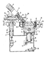
- the figure shows schematically the mounting device in section.
- the device has a base frame on which a rim holder 2 is provided.
- a column guide 3 with a horizontally movable mounting arm 4 is arranged on the side of the base frame 1.
- the mounting arm 4 carries a mounting unit 5.
- the rim holder 2 preferably consists of three or four clamping arms 6, which can be moved radially by means of cylinder units 7 in a known manner.
- the clamping arms 6 have clamping elements 8 at their outer ends, with which the rim 9 is received.
- the rim 9 can, however, also be tensioned by means of a central tensioning unit which is known per se and is not shown in more detail and which engages the center hole of the rim 8.
- the rim receptacle 2 is also rotatably supported by means of the ball bearings 10 and has a braking device 11 at the lower end, which is preferably designed as a disc brake.
- the braking device can also be designed as a plain bearing with a predetermined coefficient of friction.
- the assembly unit 5 consists of a drive unit 6, preferably an electric motor with an upstream transmission, a shaft coupling 12, a drive shaft 13 and the assembly tool 14.
- the mounting tool 14 can be designed as a conical roller or, as shown in the exemplary embodiment, as a double-sided conical roller.
- the mounting unit 5 is mounted on a mounting arm 4 and can be moved horizontally manually or by means of a drive unit.
- the mounting arm 4 is mounted on guide rollers 15.
- the mounting tool 14 is pressed in the direction of the fig horn 17 via a horizontally acting pressure cylinder 16 in connection with a clamping plate 18.
- a compression spring 19 pushes the clamping plate 18 back into the starting position after venting the pressure cylinder 16, as a result of which the mounting arm 4 can be freely moved with the mounting unit 5.
- a column 20 is guided vertically in guide rollers 30 and is moved by means of a lowering cylinder 21.
- the lowering cylinder 21 is subjected to a constant pressure, which is regulated in such a way that the weight of the entire mounting unit is compensated for and thus a simple and easy adaptation of the mounting unit 5 to the different wheel widths is possible.
- the column 20 is locked in connection with a clamping plate 23 by means of a further clamping cylinder 22. To return to the starting position of the clamping plate 23, a return spring, not shown, can also be provided.
- the cylinders 7, 16, 22, 21 can be controlled in a known manner by actuating corresponding pedals 24 and / or turning handles 29.
- the clamping device 26 can be designed as a bracket 27 and fix the upper and lower tire bead 17 in the drop center of the rim 9, the bracket 27 being supported against the tire 25 by an adjusting screw 28.
- the clamping device 26 can also be designed such that it is supported in the center hole of the rim 9 and presses the tire bead 17 into the drop center of the rim 9 by means of a radially movable arm (not shown).
- the rim holder 2 is screwed in such that the clamping device 26 is arranged next to the assembly unit 5. Subsequently, the mounting tool 14 is adjusted in the vertical and horizontal directions so that it presses the tire bead over the rim flange 17.
- the pressure cylinder 16 and the clamping cylinder Linder 22 actuated so that the mounting tool is biased even stronger against the rim flange 17 by the clamping plates 18 and 23.
- This preload can compensate for eccentric and axial runout of the rim 9 and any eccentric clamping of the rim 9 on the rim receptacle 2.
- the mounting tool 14 is driven by the drive unit 6, so that the clamped rim 9 together with the tire 25 is moved under the rotating mounting tool 14.
- the tire bead is hereby rolled over the rim flange 17 into the drop center of the rim 9.
- a torque difference between the driven assembly tool 14 and the rotating unit tire and rim is necessary.
- This difference is generated by a braking device 11, which is preferably arranged at the lower end of the rim receptacle 2 and is designed in particular as a disc brake.
- the braking force is set so high that damage-free rolling can take place.
- the mounting unit 5 is inclined in addition to the inclination to the axis of the rim receptacle 2 in the direction of the rolling movement, so that the tire bead is pushed even more into the drop center of the rim 9 and no bulges form on the tire bead circumference at the end of the mounting process which could make it very difficult or impossible to curl up.
- two assembly units 5 can also be used, which simultaneously pull up the upper and lower bead.
- the assembly tools 14 are driven in opposite directions.
- the wheel holder 2 can also be arranged horizontally for design reasons.
- the wheel After the winding process, the wheel is filled with air in a known manner.
Claims (10)
Applications Claiming Priority (2)
| Application Number | Priority Date | Filing Date | Title |
|---|---|---|---|
| DE19843401476 DE3401476A1 (de) | 1984-01-18 | 1984-01-18 | Montagevorrichtung fuer reifen |
| DE3401476 | 1984-01-18 |
Publications (3)
| Publication Number | Publication Date |
|---|---|
| EP0154715A2 EP0154715A2 (fr) | 1985-09-18 |
| EP0154715A3 EP0154715A3 (en) | 1986-10-22 |
| EP0154715B1 true EP0154715B1 (fr) | 1988-12-07 |
Family
ID=6225180
Family Applications (1)
| Application Number | Title | Priority Date | Filing Date |
|---|---|---|---|
| EP84115991A Expired EP0154715B1 (fr) | 1984-01-18 | 1984-12-20 | Dispositif de montage pour pneumatiques |
Country Status (4)
| Country | Link |
|---|---|
| US (1) | US4694875A (fr) |
| EP (1) | EP0154715B1 (fr) |
| JP (1) | JPS60163713A (fr) |
| DE (1) | DE3401476A1 (fr) |
Families Citing this family (21)
| Publication number | Priority date | Publication date | Assignee | Title |
|---|---|---|---|---|
| DE3334203A1 (de) * | 1983-09-22 | 1985-04-18 | Continental Gummi-Werke Ag, 3000 Hannover | Montagevorrichtung fuer fahrzeugluftreifen |
| DE3504903A1 (de) * | 1985-02-13 | 1986-08-14 | Continental Gummi-Werke Ag, 3000 Hannover | Verfahren und vorrichtung zur montage von fahrzeugluftreifen |
| DE3583145D1 (de) * | 1985-09-04 | 1991-07-11 | Schenck Auto Service Geraete | Verfahren zur montage oder demontage eines fahrzeugluftreifens sowie vorrichtung zur durchfuehrung des verfahrens. |
| DE3727817A1 (de) * | 1987-08-20 | 1989-03-02 | Weilnhammer Maschb Gmbh | Montagevorrichtung fuer mindestens einen reifen |
| DE3733779A1 (de) * | 1987-10-06 | 1989-04-20 | Weilnhammer Maschb Gmbh | Montagevorrichtung fuer mindestens einen reifen |
| DE8800372U1 (fr) * | 1988-01-14 | 1988-03-24 | Stahlgruber Otto Gruber Gmbh & Co, 8000 Muenchen, De | |
| EP0338642A3 (fr) * | 1988-04-20 | 1990-05-30 | du Quesne, Francis | Appareil pour monter les pneus des roues de véhicules automobiles |
| FR2635052A1 (fr) * | 1988-08-08 | 1990-02-09 | Vauthier Philippe | Dispositif d'aide au montage d'un bandage de pneumatique sur la jante d'une roue |
| US4969499A (en) * | 1989-08-30 | 1990-11-13 | Hennessey Industries, Inc. | Tire mounting apparatus |
| DE8912180U1 (fr) * | 1989-10-12 | 1989-12-07 | Weilnhammer Maschinenbau Gmbh, 8250 Dorfen, De | |
| IT1287640B1 (it) * | 1996-05-03 | 1998-08-06 | Corghi Spa | Macchina per il montaggio e lo smontaggio dei pneumatici sui e dai rispettivi cerchioni |
| DE29703048U1 (de) * | 1997-02-20 | 1997-04-24 | Weilnhammer Maschb Gmbh | Montagevorrichtung für mindestens einen Reifen |
| IT1310170B1 (it) * | 1999-02-04 | 2002-02-11 | Giuliano Srl | Macchina per il montaggio e lo smontaggio di pneumatici di tipospeciale |
| US6179033B1 (en) * | 1999-05-03 | 2001-01-30 | Norman P. Demers | Method and apparatus for seating tubeless tires |
| US6557610B2 (en) * | 1999-12-23 | 2003-05-06 | Fori Automation, Inc. | Tire bead seating station |
| DE10116469B4 (de) * | 2001-04-03 | 2006-08-03 | Hofmann Maschinen- Und Anlagenbau Gmbh | Verfahren zum Aufziehen eines Kraftfahrzeugreifens auf eine Felge eines Scheibenrades |
| US6536501B1 (en) * | 2001-10-10 | 2003-03-25 | Kenn Bishop | Tire changing and bead breaker apparatus |
| ITVR20050043A1 (it) * | 2005-04-07 | 2006-10-08 | Butler Eng & Marketing | Macchina monta-smontagomme con utensile di montaggio/smontaggio ribaltabile |
| ITTO20060285A1 (it) * | 2006-04-14 | 2007-10-15 | Bridgestone Corp | Macchina per l'assemblaggio e disassemblaggio di uno pneumatico provvisto di un anello rigido interno anti-appiattimento |
| US8991038B2 (en) * | 2008-09-04 | 2015-03-31 | Android Industries Llc | Robotic indexing station |
| US20120091209A1 (en) | 2009-06-29 | 2012-04-19 | Elizabeth Hotaling | Flexible middle layer for rfid patch on tires |
Family Cites Families (11)
| Publication number | Priority date | Publication date | Assignee | Title |
|---|---|---|---|---|
| FR403591A (fr) * | 1909-06-02 | 1909-11-08 | William Baldwin Fitts | Outil pour le démontage et la remise en place des bandages pneumatiques |
| DE830303C (de) * | 1950-04-02 | 1952-02-04 | Fritz Heinlein Altmannshausen | Vorrichtung zum Abnehmen und Auflegen von Reifendecken auf Radfelgen |
| FR1333160A (fr) * | 1962-06-13 | 1963-07-26 | Presse portative tournante permettant le démontage des pneumatiques | |
| US3522832A (en) * | 1967-11-01 | 1970-08-04 | Ludwig Held | Tire mounting and demounting machine |
| US3942575A (en) * | 1974-08-09 | 1976-03-09 | Tuxco Corporation | Portable tire changing apparatus and method for mounting and demounting heavy duty tires on a wheel |
| DE7520883U (de) * | 1975-07-01 | 1976-03-18 | Gebr. Hofmann Kg Maschinenfabrik, 6100 Darmstadt | Montier- und demontiermaschine fuer kraftfahrzeugreifen, insbesondere kraftfahrzeugreifen fuer lastkraftwagen |
| DE2715195A1 (de) * | 1976-04-07 | 1977-12-22 | Victor Duquesne | Vorrichtung zum aufziehen und abnehmen eines autoreifens |
| FR2391864A1 (fr) * | 1976-10-06 | 1978-12-22 | Michelin & Cie | Machine a monter/demonter les pneumatiques |
| US4061173A (en) * | 1976-12-29 | 1977-12-06 | The Coats Company, Inc. | Tire servicing apparatus |
| EP0042363B1 (fr) * | 1980-06-12 | 1985-01-23 | Snap-on Equipment Srl a unico socio. | Appareil pour le montage et démontage de pneumatiques |
| DE3334203A1 (de) * | 1983-09-22 | 1985-04-18 | Continental Gummi-Werke Ag, 3000 Hannover | Montagevorrichtung fuer fahrzeugluftreifen |
-
1984
- 1984-01-18 DE DE19843401476 patent/DE3401476A1/de not_active Ceased
- 1984-12-20 EP EP84115991A patent/EP0154715B1/fr not_active Expired
-
1985
- 1985-01-14 JP JP60004839A patent/JPS60163713A/ja active Pending
- 1985-01-18 US US06/692,425 patent/US4694875A/en not_active Expired - Fee Related
Also Published As
| Publication number | Publication date |
|---|---|
| JPS60163713A (ja) | 1985-08-26 |
| US4694875A (en) | 1987-09-22 |
| DE3401476A1 (de) | 1985-07-25 |
| EP0154715A2 (fr) | 1985-09-18 |
| EP0154715A3 (en) | 1986-10-22 |
Similar Documents
| Publication | Publication Date | Title |
|---|---|---|
| EP0154715B1 (fr) | Dispositif de montage pour pneumatiques | |
| EP1543308B1 (fr) | Station d'equilibrage de roues equipee d'un dispositif de serrage basculant | |
| DE2162775A1 (de) | Bandaufwickler | |
| DE1246291B (de) | Blatttransport- und Ausrichtvorrichtung | |
| DE2213779C3 (de) | Vorrichtung für die Demontage und Montage von Reifen auf Felgen | |
| DE3334203C2 (fr) | ||
| DE102006055605A1 (de) | Reifenmontiervorrichtung | |
| DE1171603B (de) | Vorrichtung zum Aufbau von Luftreifenrohlingen | |
| EP2114702A2 (fr) | Dispositif de montage et procédé de montage et de démontage d'un pneumatique de véhicule sur une jante | |
| EP0556623A1 (fr) | Appareil de rechapage | |
| DE60028102T2 (de) | Maschine für das Montieren und Demontieren von Spezialreifen | |
| DE4431878A1 (de) | Verfahren und Vorrichtung zm Konditionieren von Klebe-Ausgleichsgewichten für Kraftfahrzeugfelgen | |
| DE2529343A1 (de) | Verfahren und vorrichtung zum montieren und demontieren von kraftfahrzeugreifen, insbesondere kraftfahrzeugreifen fuer lastkraftwagen | |
| DE3108142A1 (de) | "vorrichtung zum auflegen von profilstreifen auf drahtkerne" | |
| WO2003104118A2 (fr) | Element d'entrainement | |
| DE3735557C1 (de) | Stellvorrichtung fuer einen Spannkopf zum axialen Einspannen von Wickelhuelsen | |
| DE2420329C3 (de) | Verfahren und Vorrichtung zum Aufbauen eines Gürtels für einen Luftreifen | |
| DE2553556C3 (de) | Verstellvorrichtung an fotografischen Vergrößerungs- oder Reprogeräten | |
| DE3438615A1 (de) | Montagevorrichtung fuer fahrzeugluftreifen | |
| EP0204878B1 (fr) | Laminoir en croix | |
| DE2226331C3 (de) | Anrollvorrichtung für Maschinen zum Aufbauen von Luftreifen | |
| DE3344737A1 (de) | Vorrichtung zum verbessern des laufverhaltens von fahrzeugraedern | |
| DE2059583A1 (de) | Verfahren und Vorrichtung zur Rueckbildung von Deformationen eines Reifens | |
| DE1579055C (de) | Reifenaufbaumaschine mit Anrollvor richtungen zum Verbinden der Gewebejagen eines Reifenrohhngs | |
| DE7520883U (de) | Montier- und demontiermaschine fuer kraftfahrzeugreifen, insbesondere kraftfahrzeugreifen fuer lastkraftwagen |
Legal Events
| Date | Code | Title | Description |
|---|---|---|---|
| PUAI | Public reference made under article 153(3) epc to a published international application that has entered the european phase |
Free format text: ORIGINAL CODE: 0009012 |
|
| AK | Designated contracting states |
Designated state(s): FR GB IT NL SE |
|
| PUAL | Search report despatched |
Free format text: ORIGINAL CODE: 0009013 |
|
| AK | Designated contracting states |
Kind code of ref document: A3 Designated state(s): FR GB IT NL SE |
|
| 17P | Request for examination filed |
Effective date: 19870416 |
|
| 17Q | First examination report despatched |
Effective date: 19870911 |
|
| GRAA | (expected) grant |
Free format text: ORIGINAL CODE: 0009210 |
|
| RAP3 | Party data changed (applicant data changed or rights of an application transferred) |
Owner name: GEBR. HOFMANN GMBH & CO. KG |
|
| AK | Designated contracting states |
Kind code of ref document: B1 Designated state(s): FR GB IT NL SE |
|
| PG25 | Lapsed in a contracting state [announced via postgrant information from national office to epo] |
Ref country code: IT Free format text: LAPSE BECAUSE OF FAILURE TO SUBMIT A TRANSLATION OF THE DESCRIPTION OR TO PAY THE FEE WITHIN THE PRESCRIBED TIME-LIMIT;WARNING: LAPSES OF ITALIAN PATENTS WITH EFFECTIVE DATE BEFORE 2007 MAY HAVE OCCURRED AT ANY TIME BEFORE 2007. THE CORRECT EFFECTIVE DATE MAY BE DIFFERENT FROM THE ONE RECORDED. Effective date: 19881207 |
|
| ET | Fr: translation filed | ||
| GBT | Gb: translation of ep patent filed (gb section 77(6)(a)/1977) | ||
| R20 | Corrections of a patent specification |
Effective date: 19881216 |
|
| PLBE | No opposition filed within time limit |
Free format text: ORIGINAL CODE: 0009261 |
|
| STAA | Information on the status of an ep patent application or granted ep patent |
Free format text: STATUS: NO OPPOSITION FILED WITHIN TIME LIMIT |
|
| 26N | No opposition filed | ||
| PG25 | Lapsed in a contracting state [announced via postgrant information from national office to epo] |
Ref country code: GB Effective date: 19891220 |
|
| PG25 | Lapsed in a contracting state [announced via postgrant information from national office to epo] |
Ref country code: SE Effective date: 19891221 |
|
| PG25 | Lapsed in a contracting state [announced via postgrant information from national office to epo] |
Ref country code: NL Effective date: 19900701 |
|
| GBPC | Gb: european patent ceased through non-payment of renewal fee | ||
| NLV4 | Nl: lapsed or anulled due to non-payment of the annual fee | ||
| PG25 | Lapsed in a contracting state [announced via postgrant information from national office to epo] |
Ref country code: FR Effective date: 19900831 |
|
| REG | Reference to a national code |
Ref country code: FR Ref legal event code: ST |
|
| EUG | Se: european patent has lapsed |
Ref document number: 84115991.6 Effective date: 19900830 |