EP0154715B1 - Tyre mounting device - Google Patents
Tyre mounting device Download PDFInfo
- Publication number
- EP0154715B1 EP0154715B1 EP84115991A EP84115991A EP0154715B1 EP 0154715 B1 EP0154715 B1 EP 0154715B1 EP 84115991 A EP84115991 A EP 84115991A EP 84115991 A EP84115991 A EP 84115991A EP 0154715 B1 EP0154715 B1 EP 0154715B1
- Authority
- EP
- European Patent Office
- Prior art keywords
- fitting
- rim
- roller
- tyre
- fitting apparatus
- Prior art date
- Legal status (The legal status is an assumption and is not a legal conclusion. Google has not performed a legal analysis and makes no representation as to the accuracy of the status listed.)
- Expired
Links
Images
Classifications
-
- B—PERFORMING OPERATIONS; TRANSPORTING
- B60—VEHICLES IN GENERAL
- B60C—VEHICLE TYRES; TYRE INFLATION; TYRE CHANGING; CONNECTING VALVES TO INFLATABLE ELASTIC BODIES IN GENERAL; DEVICES OR ARRANGEMENTS RELATED TO TYRES
- B60C25/00—Apparatus or tools adapted for mounting, removing or inspecting tyres
- B60C25/01—Apparatus or tools adapted for mounting, removing or inspecting tyres for removing tyres from or mounting tyres on wheels
- B60C25/05—Machines
- B60C25/132—Machines for removing and mounting tyres
-
- B—PERFORMING OPERATIONS; TRANSPORTING
- B60—VEHICLES IN GENERAL
- B60C—VEHICLE TYRES; TYRE INFLATION; TYRE CHANGING; CONNECTING VALVES TO INFLATABLE ELASTIC BODIES IN GENERAL; DEVICES OR ARRANGEMENTS RELATED TO TYRES
- B60C25/00—Apparatus or tools adapted for mounting, removing or inspecting tyres
- B60C25/01—Apparatus or tools adapted for mounting, removing or inspecting tyres for removing tyres from or mounting tyres on wheels
- B60C25/05—Machines
- B60C25/0563—Tools interacting with the tyre and moved in relation to the tyre during operation
- B60C25/0566—Tools interacting with the tyre and moved in relation to the tyre during operation rolling only
Definitions
- the invention relates to a mounting device for tires according to the preamble of claim 1.
- Such a mounting device which is described in the older, not prepublished EP-A-0141164, is suitable for mounting tires which have been published by several publications, i.a. have also become known in the magazine "Gummibereifung", 60th year, January 1984, pages 62 to 65. It is a tire-rim combination in which the tire seat is on the radially inner side of the rim flange. The tire therefore grips around the rim from the outside and finds its grip behind the radially inwardly inclined rim flanges.
- the conventional tire mounting devices are not suitable for mounting the tire on the rim.
- the object of the invention is therefore to provide a mounting device which is suitable for mounting a tire mentioned above quickly and easily on a rim, so that it sits around the rim from the outside without bulges on the tire bead circumference behind the radially inwardly inclined rim flanges on the rim.
- the driven mounting tool rolls the tire bead over the rim flange into the drop center of the rim, with a braking device that engages the rim mount providing the torque difference between mounting tool and tire required for mounting.
- the tire bead is clamped at at least one point on the rim.
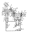
- the figure shows schematically the mounting device in section.
- the device has a base frame on which a rim holder 2 is provided.
- a column guide 3 with a horizontally movable mounting arm 4 is arranged on the side of the base frame 1.
- the mounting arm 4 carries a mounting unit 5.
- the rim holder 2 preferably consists of three or four clamping arms 6, which can be moved radially by means of cylinder units 7 in a known manner.
- the clamping arms 6 have clamping elements 8 at their outer ends, with which the rim 9 is received.
- the rim 9 can, however, also be tensioned by means of a central tensioning unit which is known per se and is not shown in more detail and which engages the center hole of the rim 8.
- the rim receptacle 2 is also rotatably supported by means of the ball bearings 10 and has a braking device 11 at the lower end, which is preferably designed as a disc brake.
- the braking device can also be designed as a plain bearing with a predetermined coefficient of friction.
- the assembly unit 5 consists of a drive unit 6, preferably an electric motor with an upstream transmission, a shaft coupling 12, a drive shaft 13 and the assembly tool 14.
- the mounting tool 14 can be designed as a conical roller or, as shown in the exemplary embodiment, as a double-sided conical roller.
- the mounting unit 5 is mounted on a mounting arm 4 and can be moved horizontally manually or by means of a drive unit.
- the mounting arm 4 is mounted on guide rollers 15.
- the mounting tool 14 is pressed in the direction of the fig horn 17 via a horizontally acting pressure cylinder 16 in connection with a clamping plate 18.
- a compression spring 19 pushes the clamping plate 18 back into the starting position after venting the pressure cylinder 16, as a result of which the mounting arm 4 can be freely moved with the mounting unit 5.
- a column 20 is guided vertically in guide rollers 30 and is moved by means of a lowering cylinder 21.
- the lowering cylinder 21 is subjected to a constant pressure, which is regulated in such a way that the weight of the entire mounting unit is compensated for and thus a simple and easy adaptation of the mounting unit 5 to the different wheel widths is possible.
- the column 20 is locked in connection with a clamping plate 23 by means of a further clamping cylinder 22. To return to the starting position of the clamping plate 23, a return spring, not shown, can also be provided.
- the cylinders 7, 16, 22, 21 can be controlled in a known manner by actuating corresponding pedals 24 and / or turning handles 29.
- the clamping device 26 can be designed as a bracket 27 and fix the upper and lower tire bead 17 in the drop center of the rim 9, the bracket 27 being supported against the tire 25 by an adjusting screw 28.
- the clamping device 26 can also be designed such that it is supported in the center hole of the rim 9 and presses the tire bead 17 into the drop center of the rim 9 by means of a radially movable arm (not shown).
- the rim holder 2 is screwed in such that the clamping device 26 is arranged next to the assembly unit 5. Subsequently, the mounting tool 14 is adjusted in the vertical and horizontal directions so that it presses the tire bead over the rim flange 17.
- the pressure cylinder 16 and the clamping cylinder Linder 22 actuated so that the mounting tool is biased even stronger against the rim flange 17 by the clamping plates 18 and 23.
- This preload can compensate for eccentric and axial runout of the rim 9 and any eccentric clamping of the rim 9 on the rim receptacle 2.
- the mounting tool 14 is driven by the drive unit 6, so that the clamped rim 9 together with the tire 25 is moved under the rotating mounting tool 14.
- the tire bead is hereby rolled over the rim flange 17 into the drop center of the rim 9.
- a torque difference between the driven assembly tool 14 and the rotating unit tire and rim is necessary.
- This difference is generated by a braking device 11, which is preferably arranged at the lower end of the rim receptacle 2 and is designed in particular as a disc brake.
- the braking force is set so high that damage-free rolling can take place.
- the mounting unit 5 is inclined in addition to the inclination to the axis of the rim receptacle 2 in the direction of the rolling movement, so that the tire bead is pushed even more into the drop center of the rim 9 and no bulges form on the tire bead circumference at the end of the mounting process which could make it very difficult or impossible to curl up.
- two assembly units 5 can also be used, which simultaneously pull up the upper and lower bead.
- the assembly tools 14 are driven in opposite directions.
- the wheel holder 2 can also be arranged horizontally for design reasons.
- the wheel After the winding process, the wheel is filled with air in a known manner.
Landscapes
- Engineering & Computer Science (AREA)
- Mechanical Engineering (AREA)
- Tires In General (AREA)
- Tyre Moulding (AREA)
- Testing Of Balance (AREA)
Description
Die Erfindung betrifft eine Montagevorrichtung für Reifen gemäß dem Oberbegriff des Anspruchs 1.The invention relates to a mounting device for tires according to the preamble of claim 1.
Eine derartige Montagevorrichtung, welche in der prioritätsälteren, nicht vorveröffentlichten EP-A-0141164 beschrieben ist, ist zur Montage von Reifen geeignet, die durch mehrere Veröffentlichungen, u.a. auch in der Zeitschrift «Gummibereifung», 60. Jahrgang, Januar 1984, Seite 62 bis 65, bekannt geworden sind. Es handelt sich um eine Reifen-Felgen-Kombination, bei der der Reifensitz auf der radial innenliegenden Seite des Felgenkranzes ist. Der Reifen greift also um die Felge von außen herum und findet seinen Halt hinter den radial nach innen geneigten Felgenhörnern.Such a mounting device, which is described in the older, not prepublished EP-A-0141164, is suitable for mounting tires which have been published by several publications, i.a. have also become known in the magazine "Gummibereifung", 60th year, January 1984, pages 62 to 65. It is a tire-rim combination in which the tire seat is on the radially inner side of the rim flange. The tire therefore grips around the rim from the outside and finds its grip behind the radially inwardly inclined rim flanges.
Aufgrund der völlig neuartigen Konzeption von Reifen und Felge sind die herkömmlichen Reifenmontiereinrichtungen nicht geeignet, den Reifen auf die Felge aufzuziehen.Due to the completely new design of the tire and rim, the conventional tire mounting devices are not suitable for mounting the tire on the rim.
Aufgabe der Erfindung ist es daher, eine Montagevorrichtung zu schaffen, die geeignet ist, einen vorstehend erwähnten Reifen schnell und problemlos auf eine Felge aufzuziehen, so daß er um die Felge von außen herum ohne Beulen am Reifenwulstumfang hinter den radial nach innen geneigten Felgenhörnern seinen Sitz auf der Felge findet.The object of the invention is therefore to provide a mounting device which is suitable for mounting a tire mentioned above quickly and easily on a rim, so that it sits around the rim from the outside without bulges on the tire bead circumference behind the radially inwardly inclined rim flanges on the rim.
Diese Aufgabe wird bei der eingangs genannten Montiervorrichtung erfindungsgemäß durch die im kennzeichnenden Teil des Anspruches 1 enthaltenen Maßnahmen gelöst.This object is achieved according to the invention in the mounting device mentioned at the outset by the measures contained in the characterizing part of claim 1.
In den Unteransprüchen sind vorteilhafte Weiterbildungen der Erfindung angegeben.Advantageous developments of the invention are specified in the subclaims.
Durch das angetriebene Montierwerkzeug wird der Reifenwulst über das Felgenhorn in das Tiefbett der Felge gerollt, wobei eine Bremseinrichtung, die an der Felgenaufnahme angreift, für die zum Aufziehen erforderliche Drehmomentdifferenz zwischen Montierwerkzeug und Reifen sorgt. Damit der Reifen auf der Felge beim Aufziehvorgang nicht weiterrutscht, wird der Reifenwulst an mindestens einer Stelle an der Felge festgeklemmt.The driven mounting tool rolls the tire bead over the rim flange into the drop center of the rim, with a braking device that engages the rim mount providing the torque difference between mounting tool and tire required for mounting. To prevent the tire from slipping on the rim during the mounting process, the tire bead is clamped at at least one point on the rim.
Die Erfindung wird nun anhand eines Ausführungsbeispiels näher erläutert.The invention will now be explained in more detail using an exemplary embodiment.
Die Figur zeigt schematisch die Montagevorrichtung im Schnitt.The figure shows schematically the mounting device in section.
Die Vorrichtung weist ein Grundgestell auf, auf dem eine Felgenaufnahme 2 vorgesehen ist. An dem Grundgestell 1 ist seitlich eine Säulenführung 3 mit einem horizontal beweglichen Montagearm 4 angeordnet. Der Montagearm 4 trägt eine Montageeinheit 5.The device has a base frame on which a
Die Felgenaufnahme 2 besteht vorzugsweise aus drei bzw. vier Spannarmen 6, die mittels Zylindereinheiten 7 in bekannter Weise radial bewegt werden können. Die Spannarme 6 weisen an ihren äußeren Enden Spannelemente 8 auf, mit denen die Felge 9 aufgenommen wird. Die Felge 9 kann jedoch auch mittels einer an sich bekannten und nicht näher dargestellten zentralen Spanneinheit gespannt werden, die am Mittelloch der Felge 8 angreift.The
Die Felgenaufnahme 2 ist ferner mittels der Kugellager 10 drehbar gelagert und weist am unteren Ende eine Bremseinrichtung 11 auf, die vorzugsweise als Scheibenbremse ausgeführt ist. Die Bremseinrichtung kann aber auch als Gleitlagerlagerung mit konstruktiv vorgegebenem Reibwert ausgeführt sein.The
Die Montageeinheit 5 besteht aus einer Antriebseinheit 6, vorzugsweise einem Elektromotor mit vorgeschaltetem Getriebe, einer Wellenkupplung 12, einer Antriebswelle 13 und dem Montierwerkzeug 14.The
Das Montierwerkzeug 14 kann als konische Rolle oder, wie in dem Ausführungsbeispiel gezeigt, als doppelseitige konische Rolle ausgeführt sein.The mounting tool 14 can be designed as a conical roller or, as shown in the exemplary embodiment, as a double-sided conical roller.
Die Montageeinheit 5 ist auf einem Montagearm 4 gelagert und kann manuell oder mittels einer Antriebseinheit horizontal verschoben werden. Der Montagearm 4 ist hierzu auf Führungsrollen 15 gelagert.The
Über einen horizontal wirkenden Andrückzylinder 16 in Verbindung mit einer Klemmplatte 18 wird das Montierwerkzeug 14 in Richtung des Feigenhornes 17 gedrückt. Eine Druckfeder 19 schiebt die Klemmplatte 18 nach dem Entlüften des Andrückzylinders 16 wieder in die Ausgangsposition, wodurch der Montagearm 4 mit der Montageeinheit 5 frei verschiebbar ist.The mounting tool 14 is pressed in the direction of the
In der Säulenführung3 ist eine Säule 20 in Führungsrollen 30 vertikal geführt und wird mittels eines Senkzylinders 21 bewegt. Der Senkzylinder 21 wird mit einem konstanten Druck beaufschlagt, der so geregelt wird, daß das Gewicht der gesamten Montiereinheit kompensiert wird und damit eine einfache und leichte Anpassung der Montageeinheit 5 an die unterschiedlichen Radbreiten möglich ist. Mittels eines weiteren Klemmzylinders 22 wird die Säule 20 in Verbindung mit einer Klemmplatte 23 arretiert. Zur Rückstellung in die Ausgangsposition der Klemmplatte 23 kann ebenfalls eine nicht dargestellte Rückstellfeder vorgesehen sein.In the
Die Zylinder 7, 16, 22, 21 können in bekannter Weise durch Betätigen entsprechender Pedale 24 und/oder Drehgriffe 29 angesteuert werden.The
Nach dem Einführen der Felge 9 in den Reifen 25 wird eine oder werden beide Reifenflanken eingestülpt und in die Reifenwulste 17 mindestens an einer Stelle des Umfanges vorzugsweise in das Tiefbett der Felge 9 eingeführt. In dieser Position werden die Reifenwulste 17 mittels einer Klemmeinrichtung 26 an der Felge 9 fixiert. Die Klemmeinrichtung 26 kann als Bügel 27 ausgeführt sein und den oberen und unteren Reifenwulst 17 im Tiefbett der Felge 9 fixieren, wobei der Bügel 27 sich über eine Stellschraube 28 gegenüber dem Reifen 25 abstützt. Die Klemmeinrichtung 26 kann jedoch auch so ausgeführt sein, daß diese sich im Mittelloch der Felge 9 abstützt und mittels eines nicht dargestellten, radial beweglichen Arms den Reifenwulst 17 in das Tiefbett der Felge 9 drückt.After the
Nach dem Aufspannen der Felge 9 auf die Felgenaufnahme 2 wird die Felgenaufnahme 2 so eingedreht, daß die Klemmeinrichtung 26 neben der Montageeinheit 5 angeordnet ist. Nachfolgend wird das Montierwerkzeug 14 in vertikaler und horizontaler Richtung so eingestellt, daß dieses den Reifenwulst über das Felgenhorn 17 drückt.After the
Nach dem Einstellen des Montierwerkzeuges 14 werden der Andrückzylinder 16 sowie der Klemmzylinder 22 betätigt, so daß das Montierwerkzeug durch die Klemmplatten 18 und 23 noch stärker gegen das Felgenhorn 17 vorgespannt wird. Durch diese Vorspannung können exzentrische und Planlauffehler der Felge 9 sowie eine eventuelle außermittige Aufspannung der Felge 9 auf der Felgenaufnahme 2 ausgeglichen werden.After setting the mounting tool 14, the
Anschliessend wird das Montierwerkzeug 14 mittels der Antriebseinheit 6 angetrieben, so daß die aufgespannte Felge 9 zusammen mit dem aufgelegten Reifen 25 unter dem sich drehenden Montierwerkzeug 14 hindurchbewegt wird.Subsequently, the mounting tool 14 is driven by the drive unit 6, so that the
Der Reifenwulst wird hierdurch über das Felgenhorn 17 in das Tiefbett der Felge 9 gerollt. Um den Reifenwulst, nachdem er über das Felgenhorn 17 gerollt ist, radial nach außen in das Tiefbett der Felge 9 zu drücken, ist eine Drehmomentdifferenz zwischen dem angetriebenen Montagewerkzeug 14 und der sich drehenden Einheit Reifen und Felge notwendig. Diese Differenz wird durch eine Bremseinrichtung 11 erzeugt, die vorzugsweise am unteren Ende der Felgenaufnahme 2 angeordnet ist und insbesondere als Scheibenbremse ausgebildet ist. Die Bremskraft wird so stark eingestellt, daß ein beschädigungsfreies Einrollen erfolgen kann.The tire bead is hereby rolled over the
Zum besseren und einfacheren Einrollen ist die Montageeinheit 5 außer der Schrägstellung zur Achse der Felgenaufnahme 2 auch noch in Richtung der Einrollbewegung geneigt, so daß der Reifenwulst noch stärker in das Tiefbett der Felge 9 geschoben wird und sich am Ende des Aufziehvorganges keine Beulen am Reifenwulstumfang bilden, die das Einrollen unter Umständen sehr erschweren bzw. unmöglich machen würden.For better and easier rolling, the
Nach dem Aufziehen des oberen Reifenwulstes auf die Felge 9 wird die Felge 9 entspannt, das Rad gedreht und nach dem erneuten Festspannen der Felge 9 der andere Reifenwulst in der zuvor beschriebenen Weise aufgezogen.After the upper tire bead has been pulled onto the
Zur Beschleunigung des Aufziehvorganges können auch zwei Montageeinheiten 5 zur Anwendung kommen, die gleichzeitig den oberen und unteren Reifenwulst aufziehen. Hierzu werden die Montagewerkzeuge 14 jedoch gegensinnig angetrieben.To accelerate the mounting process, two
Bei der Anwendung von zwei Montageeinheiten 5 kann die Radaufnahme 2 auch aus konstruktiven Gründen horizontal angeordnet sein.When using two
Nach dem Aufziehvorgang wird das Rad in bekannter Weise mit Luft gefüllt.After the winding process, the wheel is filled with air in a known manner.
Claims (10)
Applications Claiming Priority (2)
| Application Number | Priority Date | Filing Date | Title |
|---|---|---|---|
| DE19843401476 DE3401476A1 (en) | 1984-01-18 | 1984-01-18 | MOUNTING DEVICE FOR TIRES |
| DE3401476 | 1984-01-18 |
Publications (3)
| Publication Number | Publication Date |
|---|---|
| EP0154715A2 EP0154715A2 (en) | 1985-09-18 |
| EP0154715A3 EP0154715A3 (en) | 1986-10-22 |
| EP0154715B1 true EP0154715B1 (en) | 1988-12-07 |
Family
ID=6225180
Family Applications (1)
| Application Number | Title | Priority Date | Filing Date |
|---|---|---|---|
| EP84115991A Expired EP0154715B1 (en) | 1984-01-18 | 1984-12-20 | Tyre mounting device |
Country Status (4)
| Country | Link |
|---|---|
| US (1) | US4694875A (en) |
| EP (1) | EP0154715B1 (en) |
| JP (1) | JPS60163713A (en) |
| DE (1) | DE3401476A1 (en) |
Families Citing this family (21)
| Publication number | Priority date | Publication date | Assignee | Title |
|---|---|---|---|---|
| DE3334203A1 (en) * | 1983-09-22 | 1985-04-18 | Continental Gummi-Werke Ag, 3000 Hannover | AIR TIRE ASSEMBLY DEVICE |
| DE3504903A1 (en) * | 1985-02-13 | 1986-08-14 | Continental Gummi-Werke Ag, 3000 Hannover | METHOD AND DEVICE FOR MOUNTING AIR TIRES |
| DE3583145D1 (en) * | 1985-09-04 | 1991-07-11 | Schenck Auto Service Geraete | METHOD FOR ASSEMBLING OR DISASSEMBLING A TIRE FOR VEHICLES, AND DEVICE FOR IMPLEMENTING THE METHOD. |
| DE3727817A1 (en) * | 1987-08-20 | 1989-03-02 | Weilnhammer Maschb Gmbh | ASSEMBLY DEVICE FOR AT LEAST ONE TIRE |
| DE3733779A1 (en) * | 1987-10-06 | 1989-04-20 | Weilnhammer Maschb Gmbh | ASSEMBLY DEVICE FOR AT LEAST ONE TIRE |
| DE8800372U1 (en) * | 1988-01-14 | 1988-03-24 | Stahlgruber Otto Gruber Gmbh & Co, 8000 Muenchen, De | |
| EP0338642A3 (en) * | 1988-04-20 | 1990-05-30 | du Quesne, Francis | Apparatus for mounting automotive vehicle tyres |
| FR2635052A1 (en) * | 1988-08-08 | 1990-02-09 | Vauthier Philippe | Device for aiding with mounting a tyre tread strip on a wheel rim |
| US4969499A (en) * | 1989-08-30 | 1990-11-13 | Hennessey Industries, Inc. | Tire mounting apparatus |
| DE8912180U1 (en) * | 1989-10-12 | 1989-12-07 | Weilnhammer Maschinenbau Gmbh, 8250 Dorfen, De | |
| IT1287640B1 (en) * | 1996-05-03 | 1998-08-06 | Corghi Spa | MACHINE FOR THE ASSEMBLY AND DISASSEMBLY OF TIRES ON AND FROM THE RESPECTIVE RIMS |
| DE29703048U1 (en) * | 1997-02-20 | 1997-04-24 | Weilnhammer Maschb Gmbh | Mounting device for at least one tire |
| IT1310170B1 (en) * | 1999-02-04 | 2002-02-11 | Giuliano Srl | MACHINE FOR THE ASSEMBLY AND DISASSEMBLY OF SPECIAL TYPE TIRES |
| US6179033B1 (en) * | 1999-05-03 | 2001-01-30 | Norman P. Demers | Method and apparatus for seating tubeless tires |
| US6557610B2 (en) * | 1999-12-23 | 2003-05-06 | Fori Automation, Inc. | Tire bead seating station |
| DE10116469B4 (en) * | 2001-04-03 | 2006-08-03 | Hofmann Maschinen- Und Anlagenbau Gmbh | A method for mounting a motor vehicle tire on a rim of a disc wheel |
| US6536501B1 (en) * | 2001-10-10 | 2003-03-25 | Kenn Bishop | Tire changing and bead breaker apparatus |
| ITVR20050043A1 (en) * | 2005-04-07 | 2006-10-08 | Butler Eng & Marketing | TIRE ASSEMBLY MACHINE WITH TIPPING ASSEMBLY / DISASSEMBLY TOOL |
| ITTO20060285A1 (en) * | 2006-04-14 | 2007-10-15 | Bridgestone Corp | MACHINE FOR ASSEMBLY AND DISASSEMBLY OF A TIRE EQUIPPED WITH AN ANTI-APPIACTIVE INTERNAL RIGID RING |
| US8991038B2 (en) * | 2008-09-04 | 2015-03-31 | Android Industries Llc | Robotic indexing station |
| US20120091209A1 (en) | 2009-06-29 | 2012-04-19 | Elizabeth Hotaling | Flexible middle layer for rfid patch on tires |
Family Cites Families (11)
| Publication number | Priority date | Publication date | Assignee | Title |
|---|---|---|---|---|
| FR403591A (en) * | 1909-06-02 | 1909-11-08 | William Baldwin Fitts | Tool for removing and replacing pneumatic tires |
| DE830303C (en) * | 1950-04-02 | 1952-02-04 | Fritz Heinlein Altmannshausen | Device for removing and placing tire covers on wheel rims |
| FR1333160A (en) * | 1962-06-13 | 1963-07-26 | Rotating portable press allowing the dismantling of tires | |
| US3522832A (en) * | 1967-11-01 | 1970-08-04 | Ludwig Held | Tire mounting and demounting machine |
| US3942575A (en) * | 1974-08-09 | 1976-03-09 | Tuxco Corporation | Portable tire changing apparatus and method for mounting and demounting heavy duty tires on a wheel |
| DE7520883U (en) * | 1975-07-01 | 1976-03-18 | Gebr. Hofmann Kg Maschinenfabrik, 6100 Darmstadt | ASSEMBLING AND DISMANTLING MACHINE FOR VEHICLE TIRES, IN PARTICULAR VEHICLE TIRES FOR TRUCK |
| DE2715195A1 (en) * | 1976-04-07 | 1977-12-22 | Victor Duquesne | Tyre removal and fitting machine - has table with revolving wheel support and sliding vertical post carrying tool |
| FR2391864A1 (en) * | 1976-10-06 | 1978-12-22 | Michelin & Cie | TIRE ASSEMBLY / DISASSEMBLY MACHINE |
| US4061173A (en) * | 1976-12-29 | 1977-12-06 | The Coats Company, Inc. | Tire servicing apparatus |
| DE3168448D1 (en) * | 1980-06-12 | 1985-03-07 | Gs Srl | A machine for the removal and fitting of pneumatic tyres |
| DE3334203A1 (en) * | 1983-09-22 | 1985-04-18 | Continental Gummi-Werke Ag, 3000 Hannover | AIR TIRE ASSEMBLY DEVICE |
-
1984
- 1984-01-18 DE DE19843401476 patent/DE3401476A1/en not_active Ceased
- 1984-12-20 EP EP84115991A patent/EP0154715B1/en not_active Expired
-
1985
- 1985-01-14 JP JP60004839A patent/JPS60163713A/en active Pending
- 1985-01-18 US US06/692,425 patent/US4694875A/en not_active Expired - Fee Related
Also Published As
| Publication number | Publication date |
|---|---|
| DE3401476A1 (en) | 1985-07-25 |
| JPS60163713A (en) | 1985-08-26 |
| US4694875A (en) | 1987-09-22 |
| EP0154715A3 (en) | 1986-10-22 |
| EP0154715A2 (en) | 1985-09-18 |
Similar Documents
| Publication | Publication Date | Title |
|---|---|---|
| EP0154715B1 (en) | Tyre mounting device | |
| DE2162775A1 (en) | Tape rewinder | |
| DE1246291B (en) | Sheet transport and alignment device | |
| DE2213779C3 (en) | Device for removing and assembling tires on rims | |
| DE3334203C2 (en) | ||
| DE102006055605A1 (en) | Reifenmontiervorrichtung | |
| DE1171603B (en) | Device for building up pneumatic tires | |
| WO2008080584A2 (en) | Mounting device, and method for mounting and dismounting a vehicle tire on and from a rim | |
| EP0556623A1 (en) | Recapping apparatus | |
| DE60028102T2 (en) | Machine for mounting and dismounting special tires | |
| DE4431878A1 (en) | Adhesive balance weight for automobile vehicle wheel rim | |
| DE2529343A1 (en) | Tyre fitting and removal rig - with contoured roller to exert even pressure on tyre walls carried by turntable | |
| DE3108142A1 (en) | Apparatus for laying profile strips on bead wires | |
| DE3735557C1 (en) | Adjustment device for a clamping head for the axial clamping of winding sleeves | |
| DE2420329C3 (en) | Method and apparatus for building a belt for a pneumatic tire | |
| DE2553556C3 (en) | Adjustment device on photographic enlargers or repro devices | |
| DE3438615A1 (en) | Fitting device for pneumatic vehicle tyres | |
| EP0204878B1 (en) | Cross-rolling mill | |
| DE2226331C3 (en) | Rolling device for machines for building pneumatic tires | |
| DE3344737A1 (en) | Device for improving the running behaviour of vehicle wheels | |
| DE2059583A1 (en) | Method and device for the recovery of deformations of a tire | |
| DE2822531A1 (en) | Photogravure printing press form cylinder pressure system - has ram adjusted yoke shoes supported by screw and nut drive | |
| DE1579055C (en) | Tire building machine with roll-on devices for connecting the fabric hunts of a raw tire | |
| DE7520883U (en) | ASSEMBLING AND DISMANTLING MACHINE FOR VEHICLE TIRES, IN PARTICULAR VEHICLE TIRES FOR TRUCK | |
| EP0742112A2 (en) | Process and device for mounting spokes of a wheel provided with hub and spokes |
Legal Events
| Date | Code | Title | Description |
|---|---|---|---|
| PUAI | Public reference made under article 153(3) epc to a published international application that has entered the european phase |
Free format text: ORIGINAL CODE: 0009012 |
|
| AK | Designated contracting states |
Designated state(s): FR GB IT NL SE |
|
| PUAL | Search report despatched |
Free format text: ORIGINAL CODE: 0009013 |
|
| AK | Designated contracting states |
Kind code of ref document: A3 Designated state(s): FR GB IT NL SE |
|
| 17P | Request for examination filed |
Effective date: 19870416 |
|
| 17Q | First examination report despatched |
Effective date: 19870911 |
|
| GRAA | (expected) grant |
Free format text: ORIGINAL CODE: 0009210 |
|
| RAP3 | Party data changed (applicant data changed or rights of an application transferred) |
Owner name: GEBR. HOFMANN GMBH & CO. KG |
|
| AK | Designated contracting states |
Kind code of ref document: B1 Designated state(s): FR GB IT NL SE |
|
| PG25 | Lapsed in a contracting state [announced via postgrant information from national office to epo] |
Ref country code: IT Free format text: LAPSE BECAUSE OF FAILURE TO SUBMIT A TRANSLATION OF THE DESCRIPTION OR TO PAY THE FEE WITHIN THE PRESCRIBED TIME-LIMIT;WARNING: LAPSES OF ITALIAN PATENTS WITH EFFECTIVE DATE BEFORE 2007 MAY HAVE OCCURRED AT ANY TIME BEFORE 2007. THE CORRECT EFFECTIVE DATE MAY BE DIFFERENT FROM THE ONE RECORDED. Effective date: 19881207 |
|
| ET | Fr: translation filed | ||
| GBT | Gb: translation of ep patent filed (gb section 77(6)(a)/1977) | ||
| R20 | Corrections of a patent specification |
Effective date: 19881216 |
|
| PLBE | No opposition filed within time limit |
Free format text: ORIGINAL CODE: 0009261 |
|
| STAA | Information on the status of an ep patent application or granted ep patent |
Free format text: STATUS: NO OPPOSITION FILED WITHIN TIME LIMIT |
|
| 26N | No opposition filed | ||
| PG25 | Lapsed in a contracting state [announced via postgrant information from national office to epo] |
Ref country code: GB Effective date: 19891220 |
|
| PG25 | Lapsed in a contracting state [announced via postgrant information from national office to epo] |
Ref country code: SE Effective date: 19891221 |
|
| PG25 | Lapsed in a contracting state [announced via postgrant information from national office to epo] |
Ref country code: NL Effective date: 19900701 |
|
| GBPC | Gb: european patent ceased through non-payment of renewal fee | ||
| NLV4 | Nl: lapsed or anulled due to non-payment of the annual fee | ||
| PG25 | Lapsed in a contracting state [announced via postgrant information from national office to epo] |
Ref country code: FR Effective date: 19900831 |
|
| REG | Reference to a national code |
Ref country code: FR Ref legal event code: ST |
|
| EUG | Se: european patent has lapsed |
Ref document number: 84115991.6 Effective date: 19900830 |