EP0151849A2 - Circuit de stockage d'information utilisant des fusibles fondus et non-fondus - Google Patents
Circuit de stockage d'information utilisant des fusibles fondus et non-fondus Download PDFInfo
- Publication number
- EP0151849A2 EP0151849A2 EP84302451A EP84302451A EP0151849A2 EP 0151849 A2 EP0151849 A2 EP 0151849A2 EP 84302451 A EP84302451 A EP 84302451A EP 84302451 A EP84302451 A EP 84302451A EP 0151849 A2 EP0151849 A2 EP 0151849A2
- Authority
- EP
- European Patent Office
- Prior art keywords
- circuit
- fuses
- fuse
- set forth
- power supply
- Prior art date
- Legal status (The legal status is an assumption and is not a legal conclusion. Google has not performed a legal analysis and makes no representation as to the accuracy of the status listed.)
- Granted
Links
Images


Classifications
-
- G—PHYSICS
- G11—INFORMATION STORAGE
- G11C—STATIC STORES
- G11C29/00—Checking stores for correct operation ; Subsequent repair; Testing stores during standby or offline operation
- G11C29/70—Masking faults in memories by using spares or by reconfiguring
- G11C29/78—Masking faults in memories by using spares or by reconfiguring using programmable devices
- G11C29/785—Masking faults in memories by using spares or by reconfiguring using programmable devices with redundancy programming schemes
-
- G—PHYSICS
- G11—INFORMATION STORAGE
- G11C—STATIC STORES
- G11C11/00—Digital stores characterised by the use of particular electric or magnetic storage elements; Storage elements therefor
- G11C11/21—Digital stores characterised by the use of particular electric or magnetic storage elements; Storage elements therefor using electric elements
- G11C11/34—Digital stores characterised by the use of particular electric or magnetic storage elements; Storage elements therefor using electric elements using semiconductor devices
-
- G—PHYSICS
- G11—INFORMATION STORAGE
- G11C—STATIC STORES
- G11C17/00—Read-only memories programmable only once; Semi-permanent stores, e.g. manually-replaceable information cards
-
- G—PHYSICS
- G11—INFORMATION STORAGE
- G11C—STATIC STORES
- G11C17/00—Read-only memories programmable only once; Semi-permanent stores, e.g. manually-replaceable information cards
- G11C17/14—Read-only memories programmable only once; Semi-permanent stores, e.g. manually-replaceable information cards in which contents are determined by selectively establishing, breaking or modifying connecting links by permanently altering the state of coupling elements, e.g. PROM
- G11C17/16—Read-only memories programmable only once; Semi-permanent stores, e.g. manually-replaceable information cards in which contents are determined by selectively establishing, breaking or modifying connecting links by permanently altering the state of coupling elements, e.g. PROM using electrically-fusible links
-
- G—PHYSICS
- G11—INFORMATION STORAGE
- G11C—STATIC STORES
- G11C17/00—Read-only memories programmable only once; Semi-permanent stores, e.g. manually-replaceable information cards
- G11C17/14—Read-only memories programmable only once; Semi-permanent stores, e.g. manually-replaceable information cards in which contents are determined by selectively establishing, breaking or modifying connecting links by permanently altering the state of coupling elements, e.g. PROM
- G11C17/18—Auxiliary circuits, e.g. for writing into memory
Definitions
- the present invention relates to an information storing circuit using blown and unblown fuses for use in, for example, a redundancy circuit of a large capacity random access memory (RAM) device, or a trimming circuit of an integrated circuit device.
- RAM random access memory
- a large number of memory cells are arranged along rows and columns.
- the density of defects generated in such a semiconductor memory device during the manufacture thereof is relatively independent of the integration density of the device. Rather, it derives from the semiconductor manufacturing technology. In general, the higher the integration density of the device, the greater the ratio of normal memory cells to defective memory cells. This is one of the advantages of increasing the integration density of a semiconductor memory device.
- redundancy memory cells To overcome the problem of defective memory cells, use is made of redundancy memory cells.
- a redundancy memory cell row or column is selected instead of the memory cell row or column including the defective memory cell.
- one or two redundancy memory cell rows or columns are usually provided.
- a redundancy control circuit comprises fuse-type read-only memories (ROM's) each having an information storing circuit.
- a unit information storing circuit in prior art devices incorporates only one fuse for each one bit information to be stored. Therefore, the information storing circuit stores data "1" or "0" by a blown fuse or an unblown fuse.
- a polycrystalline silicon fuse is blown by electrical programming or laser programming upon completion of the major part of the manufacturing process of the device, and the succeeding testing process by which the defective rows or columns are detected and the writing date is determined.
- there is a relatively large probability of recovery of a polycrystalline silicon fuse from the blown to unblown state during the life of the device Accordingly, there is also a relatively large probability of change of data stored in the information storing circuit from "1" to "0", thereby reducing the reliability of the information storing circuit.
- each unit information storing circuit for storing cne bit information comprises a plurality of, e.g., two, fuses.
- data "0" is determined by the state wherein all the fuses are in an unblown state; and data "1” is determined by a state wherein at least one of the fuses is in a blown state, while in the programing process no fuse is blown to store "0" and all the fuses are blown to store "I".
- FIG. 1 illustrates a general redundancy control circuit.
- the redundancy control circuit is comprised of fuse-type ROM's 1-0, 1-1, ..., and 1-n each receiving address signals A 0 , A 0 ; A 1 , A 1 ; ...; and A n , A n , respectively.
- Each ROM comprises one fuse which is blown or unblown in accordance with a corresponding one bit information of an address corresponding to a defective row or column (hereinafter referred to as a defective address) and makes its internal logic switching transistor connected to one of the outputs S 0 , S 1 , ..., S ncn-conductive upon coincidence of the information and its corresponding one bit of address signals.
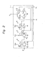
- a programming circuit 2 comprises a depletion-type transistor Q 21 , an enhancement-type transistor Q 22 for receiving a program signal P, and an enhancement-type transistor Q 23 for receiving an address signal A i .
- An information storing circuit 3 comprises a fuse F 1 , an enhancement-type transistor Q 31 turned on by the programming circuit 2, and a depletion-type transistor Q 32 serving as a load.
- An inverter 4 comprises a depletion-type transistor Q 41 , serving as a load, and an enhancement-type transistor Q 42 .
- An address coincidence detecting circuit 5 comprises enhancement-type transistors Q 51 and Q 52 for receiving address signals A i and A i , respectively, an enhancement-type transistor Q 53 for receiving an output of the information storing circuit 3 via the inverter circuit 4, and an enhancement-type transistor Q 54 for receiving the output of the information storing circuit 3.
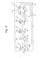
- an information storing circuit 3' comprises a latch circuit. That is, an enhancement-type transistor Q 33 , a depletion-type transistor Q 34 , and an enhancement-type transistor Q 35 are provided instead of the depletion-type transistor Q 32 of Fig. 2, thereby increasing the tolerance of the ratio of the blown and unblown resistances of the fuse F 1 .
- Fig. 3 note the inverter 4 can be omitted. In this case, the gate of the transistor Q 53 is connected directly to the fuse F 1 . However, the inverter 4 is indispensable in Fig. 7, which will be later explained.
- the fuse F 1 as shown in Figs. 2 and 3 is comprised of, for example, a polycrystalline silicon layer SI, as illustrated in Fig. 4.
- the polycrystalline silicon layer SI is connected via a contact area CONT to an aluminum layer AL serving as a conductive layer.
- the blowing portion of the fuse F 1 is, for example, 2 ⁇ m wide and 8 ⁇ m long.
- the polycrystalline silicon layer SI is exposed so as tc evapcrate the blown pclycrystalline silicon during a blowing step, thereby avoiding retrieval of the connection, i.e., recovery from the blowing state to the unblown state.
- contaminants such as sodium ions penetrating into a monocrystalline silicon substrate L 0 increase so as to interfere with the circuit operation.
- blowing can be carried out while covering the blowing portion with an insulating layer.
- the polycrystalline silicon of the blowing portion may not complete its evaporation, thereby increasing the risk cf the retrieval of the blown polycrystalline silicon.
- the possibility of change of 2 ⁇ m wide polycrystalline silicon from the unblown to blown state is very small and negligible, even if a current of about 1 to 10 ⁇ A flows through such silicon.
- a current of about 1 to 10 ⁇ A flows through such silicon.
- currents of about 100 pA to 1 mA, considerably larger than 1 to 10 ⁇ A are often supplied to such polycrystalline silicon layers, which are employed to form, for example, gate wirings in the circuit, no problem regarding blowing or change of resistance values occurs.
- the possibility of change of the polycrystalline silicon from the blown to unblown state is relatively large, due to the speciality of the blowing phenomenon and the non-uniformity of shape of the blown polycrystalline silicon.
- the gap in the fuse establishing 0 the disconnection state is often small (several 100 A).
- the high voltage applied thereto creates a strong electric field which causes a slow "flow" of the conductive material. This eventually can cause a short-circuited state, i.e., an unblown state.
- L 1 , L 2 , and L 3 designate insulating layers such as silicon dioxide (SiO 2 ) or phosphosilicate glass (PSG).
- the present invention relates to an improvement of the information storing circuit 3 of Fig. 2 and the information storing circuit 3' of Fig. 3.
- Fig. 6A which illustrates a first embodiment of the present invention
- elements F 2 , Q 31 ', Q 32 ' , Q 36 , Q 37 , and Q 38 are added to the elements of F ig. 2 .
- a fuse circuit formed by the fuse F 2 and the transistors Q 31 ' and Q 32 ' is the same as the fuse circuit formed by the fuse F 1 , and the transistors Q 31 and Q 32 .
- the depletion-type transistor Q 36 and the enhancement-type transistors Q 37 and Q 38 constitute a NAND gate circuit, which serves as an information output means.
- the transistors Q37 and Q 38 are both in an off state, so that the potential at the node N 3 is high.
- Figure 6B is a modification of Fig. 6A.
- the load depletion-type transistors Q 32 and Q 32 ' are connected in series to the fuses F 1 and F 2 , respectively.
- the channel length thereof has to be long, for example, several tens of ⁇ m to several hundreds of ⁇ m, thereby increasing the area occupied by these transistors.
- the transistors Q 32 and Q 32 ' are made enhancement-types to which a voltage from a portion other than the ROM is applied.
- Control of the voltage applied to the gates of the enhancement-type transistors Q 32 (e) and Q 32 '(e) can reduce the currents flowing through the transistors Q 3 2(e) and Q32'(e) even when the channel length of these transistors is relatively small.
- the voltage applied to the transistors Q 32 (e) and Q 32 '(e) is a definite value lower than the voltage of the power supply (V CC ) such as 2 V th generated by a circuit 6 comprising a depletion-type transistor Q 61 and enhancement-type transistors Q 62 and Q 63 .
- V th is a threshold voltage of the transistors Q 62 and Q 63 .
- Figure 6C is another modification of Fig. 6A.
- the fuses F 1 and F 2 are blown simultaneously. That is, the gates of the transistors Q 31 and Q 31 ' receive the same voltage during a blowing mode.
- a current of several tens of mA to several hundreds of mA flows through one fuse. Therefore, when two fuses are simultaneously blown, a large current flows through and has a harmful effect on the aluminum wiring.
- another programming circuit 2' is provided. The signals from the circuits 2 and 2' are applied to the gates of the transistors Q31 and Q 31 ', respectively. Selection of the fuse to be blown is controlled by voltages at the terminals P and P '.
- the problem of Fig. 6A is solved.
- FIG. 6D is still another modification of Fig. 6A.
- the voltage applied to the fuses F 1 and F 2 is a power supply voltage V CC used in the conventional circuit, which voltage is generally 5 V.
- V CC used in the conventional circuit
- Vpp' instead of V CC (V PP ' > V CC ) is connected to the fuses F 1 and F 2 , thereby giving a sufficiently high voltage to the fuses during a blowing mode.
- V CC is applied via a resistor R 1 to the fuses F 1 and F 2 .
- Fig. 7 which illustrates a second embodiment of the present invention
- elements F 2 , Q 31 ', Q 33 ' Q 34 ', Q 35 ', Q 36 ', Q 37 ', and Q 38 ' are added to the elements of Fig. 3.
- a fuse circuit formed by the fuse F 2 and the transistors Q 31 ', Q 33 ' , Q 34 ' , and Q 35 ' is the same as the fuse circuit formed by the fuse F 1 , and the transistors Q 31 , Q 33 , Q 34 , and Q35.
- the depletion-type transistor Q 36 ' and the enhancement-type transistors Q 37 ' and Q 38 ' constitute a NOR gate circuit which serves as an information output means.
- the transistors Q 37 ' and Q 3a ' are both in an on state, so that the potential at the node N 3 ' is low.
- a determination circuit 7 formed by transistors Q 71 ' Q 72 , and Q 73 is added to the elements of Fig. 6A.
- This determination circuit 7 is connected to the power supply terminal V CC via a depletion-type transistor Q 2 serving as a common load to the ROM's, as shown in Fig. 9.
- the operation of the determination circuit 7 will.be explained.
- the fuses F 1 and F 2 are both in an unblown state, the potentials at the nodes N 1 and N 2 are both high. Accordingly, the transistors Q 72 and Q 73 are both in an on state.
- the potential at the node N 3 is low. Accordingly, the transistor Q 71 is in an off state, so that the determination circuit 7 disconnects the node N 4 from the ground.
- the potential at the node N 1 is high and the potential at the node N 2 is low, so that the tran- s istor Q73 is in an on state and the transistor Q 72 is in an off state.
- the potential at the node N 3 is high. Accordingly, the transistor Q 71 is in an on state, so that the determination circuit 7 causes the potential at the node N 4 to be at the ground level.
- the determination circuit 7 disconnects the node N 4 from the grounded terminal.
- the determination circuit 7 connects the node N 4 to the ground when only one fuse is in a blown state. In other words, the determination circuit 7 determines whether or not only one fuse is blown. Note the conductivity of the transistor Q 2 is adjusted so that the potential at the node N 4 is grounded when the determination circuit 7 in at least one of the ROM's determines that only one fuse is blown.
- FIG. 9 is a block diagram of a redundancy control circuit including the ROM's of Fig. 8. That is, a circuit 8 is provided for transmitting the potential at the node N 4 to the exterior.
- This circuit 8 comprises two enchancement-type transistors Q 81 and Q 82 .
- the potential at the node N 4 is at the ground level. Accordingly, the potential at the node N 5 is - V th (V th is a threshold voltage of the transistors Q81 and Q 82 ). Therefore, the potential at a pad terminal T is -2 V th .
- the potential at the node N 4 is V CC' As a result, the potential at the node N 5 is 0, and the potential at the terminal T is -V th . That is, the above-mentioned half-abnormal state can be discriminated at the exterior by detecting whether the potential at the terminal T is -2 V th or V th . For example, when detecting such a voltage -2 V th or -V th at the terminal T, one terminal of a resistor having a value of about 500 k ⁇ is connected to the terminal T and a definite voltage such as -2 V lower than -2 V th is applied to the other terminal of the resistor. Then, a voltage at the terminal T can be measured by a voltage measuring means.
- the above-mentioned detection of such a half-abnormal state has the following three advantages.
- a product having a half-abnormal state has a low reliability, since the probability of change of another blown fuse to the unblown state is high. Products having such a half-abnormal state can be detected and removed by a detecting means in advance.
- the reliability of fuses itself can be detected by the detecting means.
- the reliability of products is a square value of the reliability of fuses. Therefore, the reliability of products over a long run can be theoretically obtained by the running of a small number of products over a short time period using the detection means.
- the determination circuit 7 can be applied to the embodiment of Fig. 7.
- the gate of the transistor Q 71 is connected to the node N 4
- the gates of the transistors Q 72 and Q 73 are connected to the fuses F 1 and F 2 , respectively.
- the programming circuits 2 and 2' are provided.
- the programming circuit 2 (2') and the transistor Q 31 (Q31) can be omitted.
- the connection of the transistors Q 53 and Q 54 of the address coincidence detecting circuit 5 is dependent upon the output polarity of the information storing circuit. That is, the connection of Fig. 2 is the same as that of Fig. 7, and the connection of Fig. 3 is the same as Figs. 6A, 6B, 6C, and 6D (Fig. 8).
- the information storing circuit 3 comprises fuses F 1 and F 2 connected-in series to each other, enhancement-type transistors Q 131 and Q 132 , and a depletion-type transistor Q 133 . That is, in the information storing circuit 3, there is no AND circuit corresponding to the transistors Q 36 , Q37 , and Q38 as illustrated in Fig. 6A, thereby simplifying the circuit configuration. '
- V FS is caused to be at the ground level. Then, when the signals P and A i are both low so as to increase the potential at the node N 101 , a large current indicated by I 1 flows through the fuse F 1 , thereby blowing it. Second, V FS is made the same as V CC . As a result, a large current indicated by I 2 flows through the fuse F 2 , thereby blowing it.
- the logical output signal from the fuses is directly obtained at node N 103 . without adding any logic gate circuit as in the preceeding embodiments.
- the fuse circuit 3' has a latch configuration so as to increase the tolerance of the ratio of the blown and unblown resistance values of the fuses. That is, enhancement-type transistors Q134 and Q 13S , and depletion-type transistor Q 135 are provided instead of the depletion-type transistor Q 133 of Fig. 10.
- the blowing mode of the fuses of Fig. 11 is the same as that of Fig. 10. Also, in the circuit of Fig. 11, when at least one of the fuses F 1 and F 2 is in a blown state, the potential at the output node N 103 of the fuse circuit 3' is low.
- the probability of change of the write state from "1" to "0" can be made very small, the reliability of the information storing circuit can be remarkably improved.
- the information storing circuit of the present invention can be also applicable to other devices such as an integrated circuit device having a trimming circuit for adjusting characteristics of internal elements after its manufacturing process to compensate the fluctuation due to the process.
- a trimming circuit may be comprised of trimming elements and the information storing circuit as described which determines the addition or deletion of the trimming elements upon testing.
Applications Claiming Priority (2)
| Application Number | Priority Date | Filing Date | Title |
|---|---|---|---|
| JP58209860A JPS60103594A (ja) | 1983-11-10 | 1983-11-10 | 情報記憶回路 |
| JP209860/83 | 1983-11-10 |
Publications (3)
| Publication Number | Publication Date |
|---|---|
| EP0151849A2 true EP0151849A2 (fr) | 1985-08-21 |
| EP0151849A3 EP0151849A3 (en) | 1987-06-16 |
| EP0151849B1 EP0151849B1 (fr) | 1990-02-21 |
Family
ID=16579821
Family Applications (1)
| Application Number | Title | Priority Date | Filing Date |
|---|---|---|---|
| EP84302451A Expired - Lifetime EP0151849B1 (fr) | 1983-11-10 | 1984-04-10 | Circuit de stockage d'information utilisant des fusibles fondus et non-fondus |
Country Status (6)
| Country | Link |
|---|---|
| US (1) | US4592025A (fr) |
| EP (1) | EP0151849B1 (fr) |
| JP (1) | JPS60103594A (fr) |
| KR (1) | KR910005596B1 (fr) |
| CA (1) | CA1216901A (fr) |
| DE (1) | DE3481391D1 (fr) |
Cited By (3)
| Publication number | Priority date | Publication date | Assignee | Title |
|---|---|---|---|---|
| EP0252325A2 (fr) * | 1986-06-11 | 1988-01-13 | Fujitsu Limited | Dispositif à semi-conducteurs comprenant un circuit de fusibles et un circuit de détection pour détecter des états des fusibles dans le circuit de fusibles |
| EP0419760A2 (fr) * | 1989-09-28 | 1991-04-03 | International Business Machines Corporation | Circuit de redondance de mémoire à consommation au repos nulle et résistant aux effets de rayonnement |
| FR2660795A1 (fr) * | 1990-04-10 | 1991-10-11 | Sgs Thomson Microelectronics | Circuit de detection de fusible. |
Families Citing this family (11)
| Publication number | Priority date | Publication date | Assignee | Title |
|---|---|---|---|---|
| JPS60201598A (ja) * | 1984-03-23 | 1985-10-12 | Fujitsu Ltd | 半導体集積回路 |
| US4686384A (en) * | 1985-08-09 | 1987-08-11 | Harris Corporation | Fuse programmable DC level generator |
| US4689494A (en) * | 1986-09-18 | 1987-08-25 | Advanced Micro Devices, Inc. | Redundancy enable/disable circuit |
| US5544111A (en) * | 1991-03-14 | 1996-08-06 | Gemplus Card International | Programming process for integrated memory, particularly for a smart card |
| US5384746A (en) * | 1994-01-28 | 1995-01-24 | Texas Instruments Incorporated | Circuit and method for storing and retrieving data |
| US5949127A (en) * | 1997-06-06 | 1999-09-07 | Integrated Device Technology, Inc. | Electrically programmable interlevel fusible link for integrated circuits |
| FR2779264B1 (fr) | 1998-05-27 | 2001-11-02 | Sgs Thomson Microelectronics | Dispositif a programmation unique de fiabilite elevee |
| US6285619B1 (en) * | 1999-11-18 | 2001-09-04 | Infineon Technologies North America Corp. | Memory cell |
| US6829737B1 (en) * | 2000-08-30 | 2004-12-07 | Micron Technology, Inc. | Method and system for storing device test information on a semiconductor device using on-device logic for determination of test results |
| US6943575B2 (en) * | 2002-07-29 | 2005-09-13 | Micron Technology, Inc. | Method, circuit and system for determining burn-in reliability from wafer level burn-in |
| WO2005015567A1 (fr) * | 2003-07-29 | 2005-02-17 | Infineon Technologies Ag | Element de memoire non volatile a securisation de donnees elevee |
Citations (1)
| Publication number | Priority date | Publication date | Assignee | Title |
|---|---|---|---|---|
| GB2029053A (en) * | 1978-08-19 | 1980-03-12 | Felten & Guilleaume Gmbh | Improvements in or Relating to Methods of Detecting and Preventing the Retransmission of Subsequently Altered Store Contents |
Family Cites Families (3)
| Publication number | Priority date | Publication date | Assignee | Title |
|---|---|---|---|---|
| US4250570B1 (en) * | 1976-07-15 | 1996-01-02 | Intel Corp | Redundant memory circuit |
| US4432070A (en) * | 1981-09-30 | 1984-02-14 | Monolithic Memories, Incorporated | High speed PROM device |
| JPS58177599A (ja) * | 1982-04-12 | 1983-10-18 | Toshiba Corp | 半導体集積回路装置 |
-
1983
- 1983-11-10 JP JP58209860A patent/JPS60103594A/ja active Granted
-
1984
- 1984-04-10 DE DE8484302451T patent/DE3481391D1/de not_active Expired - Lifetime
- 1984-04-10 EP EP84302451A patent/EP0151849B1/fr not_active Expired - Lifetime
- 1984-04-10 US US06/598,742 patent/US4592025A/en not_active Expired - Lifetime
- 1984-04-11 CA CA000451807A patent/CA1216901A/fr not_active Expired
- 1984-05-04 KR KR1019840002435A patent/KR910005596B1/ko not_active IP Right Cessation
Patent Citations (1)
| Publication number | Priority date | Publication date | Assignee | Title |
|---|---|---|---|---|
| GB2029053A (en) * | 1978-08-19 | 1980-03-12 | Felten & Guilleaume Gmbh | Improvements in or Relating to Methods of Detecting and Preventing the Retransmission of Subsequently Altered Store Contents |
Non-Patent Citations (3)
| Title |
|---|
| ELECTRONICS INTERNATIONAL, vol. 54, no. 15, 28th July 1981, pages 127-130, New York, US; R. ABBOTT et al.: "Equipping a line of memories with spare cells" * |
| L'ONDE ELECTRIQUE,vol. 55, no. 3, March 1975, pages 144-151, Paris, FR; J. SEGUIN: "Réalisation d'une mémoire programmable ECL" * |
| MICRO-ELECTRONICS JOURNAL, vol. 11, no. 5, September/October 1980, pages 15-19, Mackintosh Publications Ltd, Luton Beds, GB; R.L. CLINE: "Design limitations in large bipolar PROMs" * |
Cited By (7)
| Publication number | Priority date | Publication date | Assignee | Title |
|---|---|---|---|---|
| EP0252325A2 (fr) * | 1986-06-11 | 1988-01-13 | Fujitsu Limited | Dispositif à semi-conducteurs comprenant un circuit de fusibles et un circuit de détection pour détecter des états des fusibles dans le circuit de fusibles |
| EP0252325A3 (en) * | 1986-06-11 | 1990-01-31 | Fujitsu Limited | Semiconductor device having a fuse circuit and a detecting circuit for detecting the states of the fuses in the fuse circuit |
| EP0419760A2 (fr) * | 1989-09-28 | 1991-04-03 | International Business Machines Corporation | Circuit de redondance de mémoire à consommation au repos nulle et résistant aux effets de rayonnement |
| EP0419760A3 (en) * | 1989-09-28 | 1992-10-28 | International Business Machines Corporation | Zero standby power, radiation hardened, memory redundancy circuit |
| FR2660795A1 (fr) * | 1990-04-10 | 1991-10-11 | Sgs Thomson Microelectronics | Circuit de detection de fusible. |
| EP0453351A1 (fr) * | 1990-04-10 | 1991-10-23 | STMicroelectronics S.A. | Circuit de détection de fusible |
| US5291139A (en) * | 1990-04-10 | 1994-03-01 | Sgs-Thomson Microelectronics S.A. | Circuit for detection of the state of an integrated circuit fuse in a balanced fuse configuration |
Also Published As
| Publication number | Publication date |
|---|---|
| KR850003616A (ko) | 1985-06-20 |
| EP0151849B1 (fr) | 1990-02-21 |
| DE3481391D1 (de) | 1990-03-29 |
| EP0151849A3 (en) | 1987-06-16 |
| US4592025A (en) | 1986-05-27 |
| JPS6322399B2 (fr) | 1988-05-11 |
| KR910005596B1 (ko) | 1991-07-31 |
| CA1216901A (fr) | 1987-01-20 |
| JPS60103594A (ja) | 1985-06-07 |
Similar Documents
| Publication | Publication Date | Title |
|---|---|---|
| US5973380A (en) | Semiconductor junction antifuse circuit | |
| US5418738A (en) | Low voltage programmable storage element | |
| KR100381352B1 (ko) | 제어게이트전극과부유게이트전극사이에단락된부유게이트형기준셀을구비한반도체불휘발성메모리장치 | |
| US6157583A (en) | Integrated circuit memory having a fuse detect circuit and method therefor | |
| EP0052481B1 (fr) | Dispositif à semiconducteur ayant un circuit d'identification de l'état du dispositif | |
| US4660179A (en) | Semiconductor memory device with switching for redundant cells | |
| EP0151849B1 (fr) | Circuit de stockage d'information utilisant des fusibles fondus et non-fondus | |
| EP0355768B1 (fr) | Cellules de mémoire à semi-conducteur et dispositif de mémoire à semi-conducteur utilisant de telles cellules | |
| US6449207B2 (en) | Voltage independent fuse circuit and method | |
| JP2888034B2 (ja) | 半導体メモリ装置 | |
| KR910001533B1 (ko) | 휴즈회로와 그내의 휴즈상태 검출회로를 갖는 반도체장치 | |
| US5519650A (en) | Semiconductor device having an improved immunity to a short-circuit at a power supply line | |
| US4794568A (en) | Redundancy circuit for use in a semiconductor memory device | |
| US4707806A (en) | Semiconductor integrated circuit device having fuse-type information storing circuit | |
| EP0208555B1 (fr) | Dispositif de mémoire à semi-conducteur ayant une configuration à redondance | |
| US5625593A (en) | Memory card circuit with separate buffer chips | |
| US5390150A (en) | Semiconductor memory device with redundancy structure suppressing power consumption | |
| US5677888A (en) | Redundancy circuit for programmable integrated circuits | |
| KR950006425B1 (ko) | 반도체 메모리 장치 | |
| US5058070A (en) | High speed memory with row redundancy | |
| US5923672A (en) | Multipath antifuse circuit | |
| JPH0324000B2 (fr) | ||
| JPS6350799B2 (fr) | ||
| JP2000200498A (ja) | 半導体装置 | |
| JPH038039B2 (fr) |
Legal Events
| Date | Code | Title | Description |
|---|---|---|---|
| PUAI | Public reference made under article 153(3) epc to a published international application that has entered the european phase |
Free format text: ORIGINAL CODE: 0009012 |
|
| AK | Designated contracting states |
Designated state(s): DE FR GB |
|
| PUAL | Search report despatched |
Free format text: ORIGINAL CODE: 0009013 |
|
| AK | Designated contracting states |
Kind code of ref document: A3 Designated state(s): DE FR GB |
|
| 17P | Request for examination filed |
Effective date: 19870717 |
|
| 17Q | First examination report despatched |
Effective date: 19880506 |
|
| GRAA | (expected) grant |
Free format text: ORIGINAL CODE: 0009210 |
|
| AK | Designated contracting states |
Kind code of ref document: B1 Designated state(s): DE FR GB |
|
| REF | Corresponds to: |
Ref document number: 3481391 Country of ref document: DE Date of ref document: 19900329 |
|
| ET | Fr: translation filed | ||
| PLBE | No opposition filed within time limit |
Free format text: ORIGINAL CODE: 0009261 |
|
| STAA | Information on the status of an ep patent application or granted ep patent |
Free format text: STATUS: NO OPPOSITION FILED WITHIN TIME LIMIT |
|
| 26N | No opposition filed | ||
| REG | Reference to a national code |
Ref country code: GB Ref legal event code: IF02 |
|
| PGFP | Annual fee paid to national office [announced via postgrant information from national office to epo] |
Ref country code: FR Payment date: 20030408 Year of fee payment: 20 |
|
| PGFP | Annual fee paid to national office [announced via postgrant information from national office to epo] |
Ref country code: GB Payment date: 20030409 Year of fee payment: 20 |
|
| PGFP | Annual fee paid to national office [announced via postgrant information from national office to epo] |
Ref country code: DE Payment date: 20030417 Year of fee payment: 20 |
|
| PG25 | Lapsed in a contracting state [announced via postgrant information from national office to epo] |
Ref country code: GB Free format text: LAPSE BECAUSE OF EXPIRATION OF PROTECTION Effective date: 20040409 |
|
| REG | Reference to a national code |
Ref country code: GB Ref legal event code: PE20 |