EP0151379A2 - Anlage zum Herstellen von Formsteinen aus Schaumbeton - Google Patents
Anlage zum Herstellen von Formsteinen aus Schaumbeton Download PDFInfo
- Publication number
- EP0151379A2 EP0151379A2 EP84890239A EP84890239A EP0151379A2 EP 0151379 A2 EP0151379 A2 EP 0151379A2 EP 84890239 A EP84890239 A EP 84890239A EP 84890239 A EP84890239 A EP 84890239A EP 0151379 A2 EP0151379 A2 EP 0151379A2
- Authority
- EP
- European Patent Office
- Prior art keywords
- molds
- ring
- turntable
- plant according
- base
- Prior art date
- Legal status (The legal status is an assumption and is not a legal conclusion. Google has not performed a legal analysis and makes no representation as to the accuracy of the status listed.)
- Granted
Links
- 239000011459 moulded brick Substances 0.000 title 1
- 239000011381 foam concrete Substances 0.000 claims abstract description 18
- 230000002093 peripheral effect Effects 0.000 claims description 3
- 238000009434 installation Methods 0.000 claims 2
- 238000004519 manufacturing process Methods 0.000 abstract description 4
- 238000010924 continuous production Methods 0.000 abstract description 2
- 230000001419 dependent effect Effects 0.000 abstract description 2
- 239000004575 stone Substances 0.000 description 9
- 238000011282 treatment Methods 0.000 description 5
- 239000006260 foam Substances 0.000 description 4
- 239000000654 additive Substances 0.000 description 2
- 239000003795 chemical substances by application Substances 0.000 description 2
- 238000004140 cleaning Methods 0.000 description 2
- 238000001816 cooling Methods 0.000 description 2
- 230000008878 coupling Effects 0.000 description 2
- 238000010168 coupling process Methods 0.000 description 2
- 238000005859 coupling reaction Methods 0.000 description 2
- 238000005520 cutting process Methods 0.000 description 2
- 238000010438 heat treatment Methods 0.000 description 2
- 238000004321 preservation Methods 0.000 description 2
- 238000011144 upstream manufacturing Methods 0.000 description 2
- 230000001133 acceleration Effects 0.000 description 1
- 239000011449 brick Substances 0.000 description 1
- 239000004568 cement Substances 0.000 description 1
- 239000004927 clay Substances 0.000 description 1
- 239000004567 concrete Substances 0.000 description 1
- 230000007812 deficiency Effects 0.000 description 1
- 230000000694 effects Effects 0.000 description 1
- 239000007788 liquid Substances 0.000 description 1
- 239000000463 material Substances 0.000 description 1
- 239000000203 mixture Substances 0.000 description 1
- 239000008262 pumice Substances 0.000 description 1
- 230000000284 resting effect Effects 0.000 description 1
- 238000007789 sealing Methods 0.000 description 1
- 239000002893 slag Substances 0.000 description 1
- 239000007787 solid Substances 0.000 description 1
- 238000003860 storage Methods 0.000 description 1
- 238000010792 warming Methods 0.000 description 1
- XLYOFNOQVPJJNP-UHFFFAOYSA-N water Substances O XLYOFNOQVPJJNP-UHFFFAOYSA-N 0.000 description 1
- 239000002023 wood Substances 0.000 description 1
Images
Classifications
-
- B—PERFORMING OPERATIONS; TRANSPORTING
- B30—PRESSES
- B30B—PRESSES IN GENERAL
- B30B15/00—Details of, or accessories for, presses; Auxiliary measures in connection with pressing
- B30B15/0023—Drive arrangements for movable carriers, e.g. turntables
-
- B—PERFORMING OPERATIONS; TRANSPORTING
- B28—WORKING CEMENT, CLAY, OR STONE
- B28B—SHAPING CLAY OR OTHER CERAMIC COMPOSITIONS; SHAPING SLAG; SHAPING MIXTURES CONTAINING CEMENTITIOUS MATERIAL, e.g. PLASTER
- B28B1/00—Producing shaped prefabricated articles from the material
- B28B1/50—Producing shaped prefabricated articles from the material specially adapted for producing articles of expanded material, e.g. cellular concrete
-
- B—PERFORMING OPERATIONS; TRANSPORTING
- B28—WORKING CEMENT, CLAY, OR STONE
- B28B—SHAPING CLAY OR OTHER CERAMIC COMPOSITIONS; SHAPING SLAG; SHAPING MIXTURES CONTAINING CEMENTITIOUS MATERIAL, e.g. PLASTER
- B28B5/00—Producing shaped articles from the material in moulds or on moulding surfaces, carried or formed by, in or on conveyors irrespective of the manner of shaping
- B28B5/06—Producing shaped articles from the material in moulds or on moulding surfaces, carried or formed by, in or on conveyors irrespective of the manner of shaping in moulds on a turntable
- B28B5/08—Producing shaped articles from the material in moulds or on moulding surfaces, carried or formed by, in or on conveyors irrespective of the manner of shaping in moulds on a turntable intermittently rotated
Definitions
- the invention relates to a plant for producing molded blocks from foam concrete with molds which rest on a base forming the base of the molds, and with a filling device for the molds which are open at the top.
- the desired porosity is achieved with foam concrete by means of a prefabricated foam which is mixed with the mixture of cement, water and additives. Since the preservation of the air bubbles enclosed in the foam during curing is of particular importance, at least up to dimensional stability, all influences that support the collapse of the foam, including the effects of vibrations when handling the freshly filled molds, should be eliminated as far as possible. For this reason, the molds are placed on a solid base, which forms the bottom of the molds for easier removal from the mold, and loaded with a filling device which has to be moved from mold to mold. The foam concrete remains in the molds resting on the base, at least during a hardening period, in the molds, which ensures that the molded blocks retain their shape adequately.
- the production of molded blocks from foam concrete therefore requires comparatively large transport routes, large mold-occupying areas and expensive production halls, so that the foam concrete is usually cast in large-volume units, which are subsequently retrofitted with wires or saws cut into stones of the desired size.
- the large-volume pouring of foam concrete increases productivity, but the disadvantage must be accepted that the stones can only have flat boundary surfaces.
- the advantageous cutting with wires depends on the strength of the foam concrete, so that the cutting should be carried out at a certain degree of hardening, which is, however, hardly possible in practice.
- only aggregates up to a grain size of 2mm can be used because larger aggregates that increase strength, e.g. lava, pumice, expanded clay, slag or wood shavings, can no longer be cut with wires and sawing only after an autoclave treatment or a setting time of about 72 hours is possible.
- the invention is therefore based on the object to avoid these deficiencies and to improve a system of the type described in such a way that a continuous production of molded bricks is ensured without restrictions with regard to the shape and the additives.
- the invention achieves the stated object in that the base forming the base for the molds is part of a turntable, on which the molds are mounted in at least one concentric circle with a uniform angular spacing, that the filling device assigned to a stationary filling station connected to the turntable stationary demolding station in the direction of rotation of the turntable is immediately downstream, and that the turntable has a step drive with mutually dependent rotary steps on the angular distance of the molds.
- the base forming the base of the molds is part of a turntable, so the molds can first be moved past the stationary filling station in a self-contained row without moving relative to the base, where they are filled with the foam concrete.
- the step drive of the turntable provides for the turntable, there are certain turning steps that bring the individual molds to the filling station one after the other.
- the size of the turntable and the number of molds stored on the turntable can be adjusted depending on the cycle times so that the time for one cycle is sufficient to ensure the hardening of the shaped blocks required for demolding. In the demoulding station immediately upstream of the filling station in the direction of rotation, the shaped blocks can then be demolded and removed.
- each sector of the turntable contains the shaped stones of a certain hardening stage.
- the turntable consists of a ring which forms the base for the molds and which is concentric with the axis of rotation of the turntable and which is rotatably supported on stationary supporting rollers.
- the self-supporting ring which is supported on the support rollers, allows a limitation of the moments of inertia despite a comparatively large diameter, so that the required acceleration of the ring and its braking can be ensured economically with stepper drives.
- Sufficiently smooth running of the ring can also be achieved in order to be able to exclude vibrations which are harmful for the preservation of the air bubbles in the foam.
- the central mounting of the ring can advantageously be achieved by at least three guide rollers distributed over the circumference on a concentric peripheral surface of the ring. If the guide rollers are resiliently pressed onto the circumferential surface of the ring, for example by springs or cylinders, then the resilient can ge employment an advantageous tolerance compensation can be ensured, thermal expansion can also be taken into account.
- the stepper drive could act on the rotary table in a conventional manner via a pinion meshing with a ring gear.
- the stepper drive consists of at least one stationary supported drive cylinder which carries a gripping head for gripping drivers provided along the ring.
- the turntable is rotated further by a rotation step corresponding to the cylinder stroke. So that the turntable can be braked via the drive cylinder, the cylinder is provided with a gripping head which must have stop surfaces which act both in the direction of rotation and counter to the direction of rotation.
- a ring surrounding the drivers of the turntable fulfills this task in the simplest way.
- the stepping drive can also consist of at least two cylinders, which are supported in opposite directions and act on drivers along the ring, one of which acts as a drive cylinder and the other as a brake cylinder.
- the filling station can advantageously consist of a radial conveyor with respect to the ring, which is radially displaceably mounted in a frame and carries a scraper which can be swiveled onto the molds at its discharge end.
- the foam concrete finished in a corresponding mixer is applied to the conveyor which is moved over the molds, the molds being filled with the foam concrete falling off the conveyor.
- the loading rate is chosen to be somewhat higher than necessary in order to ensure that the molds are overfilled. With the scraper provided at the discharge end of the conveyor, the excess amount of foam concrete is stripped off the molds, which means that the molds are filled exactly ensures.
- the demolding station can have a lifting device for the molds which is adjustable radially with respect to the ring, a vertically immovable ejector for the shaped blocks which cooperates with the lifting device and a conveyor for removing the removed shaped blocks.
- the ejector is provided with differently high ejection arms so that the ejection arms are used one after the other, the ejection forces can be kept comparatively low.
- the trolley of the hoist must be aligned with the ejector. Such alignment is not necessary if the hoist trolley carries the ejector. It is not necessary to precisely align the hoist or the ejector with the conveyor.
- the filling station can be arranged inside and the demolding station outside the ring of the turntable. This arrangement also ensures a minimal angular distance between the demolding station and the filling station, which is reflected in a good utilization of the ring surface forming the base for the molds.
- placing the molds on a turntable offers the simple possibility of exposing the shaped blocks in certain hardening areas, for example a heat treatment, because this treatment, which is coordinated with a time, can be limited locally to a sector area of the turntable.
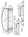
- the ring of the turntable can advantageously be covered by a non-rotatable ring hood that can be heated at least in certain sectors, so that the space to be heated is economically limited.
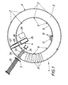
- the device shown consists essentially of a turntable 1, which forms a base 2 for the molds 3, which are uniformly distributed in a concentric circle on the turntable, and to which a stationary filling station 4 and, on the other hand, a stationary demolding station 5 are assigned, the demolding station 5 being the Filling station 4 is immediately upstream in the direction of rotation of the turntable 1.
- the turntable 1 has a self-supporting ring 6 which carries the base 2 for the molds 3 and is rotatably supported on stationary support rollers 7. To center the ring 6 are guide rollers 8 which are attached to the inner circumferential surface 9 of the ring 6 are made by springs or cylinders, which are not shown for reasons of clarity.
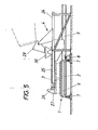
- a ring drive 10 is used to drive the ring 6, which, as shown in FIGS. 1 and 3, consists of a drive cylinder 11 acting in the direction of rotation, which is supported in a stationary manner and has a gripping head 13 which engages with drivers 12 along the ring 6.
- this gripping head 13 consists of a ring which includes the drivers 12, so that the ring 6 can not only be driven but also braked via the drive cylinder 11. So that the gripping head 13 can be plugged onto the driver 12, the drive cylinder 11 is pressed against the driver 12 via a spring 14, which press the gripping head 13 down for coupling against the force of the spring 14. To uncouple the gripping head 13 must be removed from the drivers 12, which is carried out by a separate device, which is not shown in detail. When the drive cylinder 11 is acted upon appropriately, the ring 6 is rotated via the gripper head 13, which holds one of the drivers 12, in accordance with the stroke of the drive cylinder 11.
- the gripping head 13 is to be removed from the driver 12 and the drive cylinder 11 is returned to its starting position, the gripping head 13 being plugged onto the following driver 12, so that a further turning step of the ring 6 is carried out when the cylinder 11 is loaded again can.
- a locking device can ensure the rotationally fixed mounting of the ring 6 during the resetting of the drive cylinder 11.
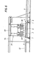
- a stepper drive 10 can be used with at least two cylinders 15 and 16 acting in opposite directions on the drivers 12, one of which serves as a drive cylinder and the other as a brake cylinder.
- the coupling of the cylinders 15 and 16 with the drivers 12 is made possible by springs 17 which press the print heads 18 of these cylinders against the drivers.
- To decouple the brake cylinder 16 its print head 18 must be lifted off the driver 12 again. This is not necessary for the drive cylinder 15 because the drivers 12 can reset the print head 18 against the force of the spring 17.
- the ring 6 of the turntable 1 is covered with a heat-insulating ring hood 19, which allows the ring surface of the turntable to be divided economically into several treatment zones, for example a storage zone, a preheating zone, a heating zone, a warming zone and a cooling zone .
- the seal between the driven ring 6 and the fixed ring hood 19 takes place via liquid-filled ring channels 20 which are provided on the ring hood 19 and protrude into the sealing webs 21.
- the resulting annular space 22 above the ring 6 can be charged with hot air, steam or cooling air via appropriate nozzles 23 in order to ensure the appropriate treatment of the shaped blocks.
- the filling station 4 has a belt conveyor 25 which can be moved radially in a frame 24 and which carries at its discharge end 26 a scraper 27 which can be swiveled onto the molds 3.
- the foam concrete to be filled which is prepared in a mixing system 28, is fed via a chute 29 to a container 30 which is pivotally mounted on the frame 24 above the belt conveyor 25, so that the foam concrete is applied from the container 30 to the belt conveyor 25 can be.
- the belt conveyor 25 is then pulled back during operation from the outside inwards over the mold located in its area, the mold being filled with foam concrete.
- the scraper 27 pivoted onto the upper mold edge smoothes the filling and conveys the wiped material to a slide or the like in order to be able to feed it back to the new mold.
- the shaped stones in the molds are hardened to a degree that allows demolding.
- the molds 3 are removed from the demolding station 5 with the aid of a lifting device 31 from that formed by the ring 6.
- Base 2 is lifted off and guided to a radial conveyor 32 on which the demolded shaped blocks are transported away.
- the trolley 33 of the hoist 31 which is mounted so as to be radially movable on a frame 34 bridging the ring 6, additionally carries an ejector 35 in the form of a plurality of ejection arms 36, by lifting the mold 3 over the ejector 35 with the aid of the hoist 31 the shaped stone can be pressed out of the mold, without additional lifting of the shaped stone, so that the drop height can advantageously remain low.
- the molds are lifted above the ejector 35, the mold can be cleaned in one operation if corresponding cleaning brushes or the like are arranged downstream of the ejection arms 36. After such cleaning, the mold can be sprayed with a release agent before it is placed on the turntable 1 again with the lifting device.
- the mold 3 prepared for a new filling reaches the area of the belt conveyor 25 of the filling station 4, at least during the next turning steps of the turntable, where it is again filled with foam concrete for the production of a further shaped block while repeating the working steps.
Landscapes
- Engineering & Computer Science (AREA)
- Mechanical Engineering (AREA)
- Manufacturing & Machinery (AREA)
- Chemical & Material Sciences (AREA)
- Ceramic Engineering (AREA)
- Devices For Post-Treatments, Processing, Supply, Discharge, And Other Processes (AREA)
- Cultivation Of Plants (AREA)
- Moulds For Moulding Plastics Or The Like (AREA)
- Moulds, Cores, Or Mandrels (AREA)
Abstract
Description
- Die Erfindung bezieht sich auf eine Anlage zum Herstellen von Formsteinen aus Schaumbeton mit Formen, die auf einer den Boden der Formen bildenden Unterlage aufruhen, und mit einer Fülleinrichtung für die oben offenen Formen.
- - Im Gegensatz zu Gasbetonen wird bei Schaumbetonen die angestrebte Porosität durch einen vorgefertigten Schaum erreicht, der dem Gemisch aus Zement, Wasser und Zuschlagstoffen zugemischt wird. Da somit dem Bewahren der im Schaum eingeschlossenen-Luftbläschen während des Aushärtens zumindest bis zur Formbeständigkeit eine besondere Bedeutung zukommt, sollen alle ein Zusammenbrechen des Schaumes unterstützenden Einflüsse, zu denen auch die Erschütterungseinflüsse beim Handhaben der frisch gefüllten Formen zählen, tunlichst ausgeschaltet werden. Aus diesem Grunde werden die Formen auf einer festen Unterlage aufgelegt, die zum leichteren Entformen den Boden der Formen bildet, und mit Hilfe einer Fülleinrichtung beschickt, die von Form zu Form bewegt werden muß. Der Schaumbeton verbleibt in den auf der Unterlage aufruhenden Formen zumindest während einer Aushärtezeit in den Formen, die eine ausreichende Formbeständigkeit der Formsteine sicherstellt. Die Herstellung von Formsteinen aus Schaumbeton bedingt demnach vergleichsweise große Transportwege, große Formbelegungsflächen und teure Produktionshallen, so daß der Schaumbeton üblicherweise in großvolumigen Einheiten gegossen wird, die nachträglich mit Drähten oder Sägen zu Steinen der gewünschten Größe geschnitten werden. Das großvolumige Gießen von Schaumbeton erhöht zwar die Produktivität, doch muß dabei der Nachteil in Kauf genommen werden, daß die Steine nur ebene Begrenzungsflächen aufweisen können. Außerdem ist das vorteilhafte Schneiden mit Drähten von der Festigkeit des Schaumbetones abhängig, so daß das Schneiden bei einem bestimmten Aushärtegrad durchge= -führt werden soll, was in der Praxis jedoch kaum möglich ist. Darüber hinaus können nur Zuschlagstoffe bis zu einer Korngröße von 2mm eingesetzt werden, weil sich größere, die Festigkeit erhöhende Zuschlagstoffe, beispielsweise Lava, Bims, Blähton, Schlacken oder Holzspäne, nicht mehr mit Drähten schneiden lassen und ein Sägen erst nach einer Autoklavbehandlung oder einer Abbindezeit von etwa 72 Stunden möglich ist.
- Der Erfindung liegt somit die Aufgabe zugrunde, diese Mängel zu vermeiden und eine Anlage der eingangs geschilderten Art so zu verbessern, daß eine kontinuierliche Herstellung von Formsteinen ohne Beschränkungen hinsichtlich der Formgebung und der Zuschlagstoffe gewährleistet wird.
- Die Erfindung löst die gestellte Aufgabe dadurch, daß die den Boden für die Formen bildende Unterlage Teil eines Drehtisches ist, auf dem die Formen in wenigstens einem konzentrischen Kreis mit gleichmäßigem Winkelabstand gelagert sind, daß die einer ortsfesten, an den Drehtisch angeschlossenen Füllstation zugeordnete Fülleinrichtung einer ortsfesten Entformungsstation in Drehrichtung des Drehtisches unmittelbar nachgeordnet ist, und daß der Drehtisch einen Schrittantrieb mit vom Winkelabstand der Formen voneinander abhängigen Drehschritten aufweist.
- Da zufolge dieser Maßnahmen die den Boden der Formen bildende Unterlage Teil eines Drehtisches ist, können die Formen ohne Bewegung gegenüber der Unterlage in einer in sich geschlossenen Reihe zuerst an der ortsfesten Füllstation vorbeibewegt werden, wo sie mit dem Schaumbeton gefüllt werden. Der Schrittantrieb des Drehtisches stellt dabei für den Drehtisch Drehschritte sicher, die die einzelnen Formen nacheinander zu der Füllstation bringen. Die Größe des Drehtisches und die Anzahl der auf dem Drehtisch gelagerten Formen können in Abhängigkeit von den Taktzeiten so abgestimmt werden, daß die Zeit für einen Umlauf ausreicht, um die zur Entformung erforderliche Aushärtung der Formsteine sicherzustellen. In der der Füllstation in Drehrichtung unmittelbar vorgeordneten Entformungsstation können dann die Formsteine entformt und abtransportiert werden. Dabei ist es in einfacher Weise möglich, den Formsteinen in bestimmten Aushärtungsstadien Sonderbehandlungen zukommen zu lassen, weil jeder Sektor des Drehtisches die Formsteine eines bestimmten Aushärtestadiums enthält. Nach der Entformung der Formsteine können die Formen nach einer entsprechenden Reinigung und einem Überziehen mit einem Trennmittel wieder auf dem Drehtisch abgestellt und neuerlich befüllt werden.
- Besonders einfache Konstruktionsverhältnisse können in weiterer Ausbildung der Erfindung erzielt werden, wenn der Drehtisch aus einem die Unterlage für die Formen bildenden, zur Drehachse des Drehtisches konzentrischen Ring besteht, der auf ortsfest gelagerten Tragrollen drehbar abgestützt ist. Der selbsttragende, auf den Tragrollen abgestützte Ring erlaubt trotz eines vergleichsweise großen Durchmessers eine Beschränkung der Trägheitsmomente, so daß die erforderliche Beschleunigung des Ringes und seine Abbremsung wirtschaftlich mit Schrittantrieben sichergestellt werden kann. Außerdem kann ein ausreichend ruhiger Lauf des Ringes erreicht werden, um für das Bewahren der Luftbläschen im Schaum schädliche Schwingungen ausschließen zu können.
- Die zentrische Lagerung des Ringes kann vorteilhaft durch wenigstens drei über den Umfang verteilt an einer konzentrischen Umfangsfläche des Ringes angestellte Führungsrollen erzielt werden. Sind die Führungsrollen an die Umfangsfläche des Ringes, beispielsweise durch Federn oder Zylinder, nachgiebig angedrückt, so kann über die nachgiebige Anstellung ein vorteilhafter Toleranzausgleich gewährleistet werden, wobei auch Wärmedehnungen berücksichtigt werden können.
- Der Schrittantrieb könnte in herkömmlicher Weise über ein mit einem Zahnkranz kämmendes Ritzel auf den Drehtisch wirken. Besonders vorteilhafte Verhältnisse ergeben sich allerdings, wenn der Schrittantrieb aus wenigstens einem ortsfest abgestützten Antriebszylinder besteht, der einen Greifkopf zum Erfassen von entlang des Ringes vorgesehenen Mitnehmern trägt. Durch eine entsprechende Beaufschlagung des Zylinders wird der Drehtisch um einen dem Zylinderhub entsprechenden Drehschritt weitergedreht. Damit der Drehtisch über den Antriebszylinder abgebremst werden kann, ist der Zylinder mit einem Greifkopf versehen, der sowohl im Drehsinn als-auch- entgegen dem Drehsinn wirkende Anschlagflächen aufweisen muß. Ein die Mitnehmer des Drehtisches umschließender Ring erfüllt diese Aufgabe in einfachster Weise.
- Um einen Greifkopf zu vermeiden, kann der Schrittantrieb aber auch aus wenigstens zwei gegensinnig auf Mitnehmer entlang des Ringes einwirkenden, ortsfest abgestützten Zylindern bestehen, von denen einer als Antriebszylinder und der andere als Bremszylinder wirkt.
- Die Füllstation kann in weiterer Ausbildung der Erfindung vorteilhaft aus einem bezüglich des Ringes radialen Förderer bestehen, der in einem Gestell radial verschiebbar gelagert ist und an seinem Abwurfende einen auf die Formen abschwenkbaren Abstreifer trägt. Der in einem entsprechenden Mischer fertiggestellte Schaumbeton wird auf-den Förderer aufgebracht, der über die Formen bewegt wird, wobei die Formen mit dem vom Förderer abfallenden Schaumbeton gefüllt werden. Die Beschickungsrate wird dabei etwas höher als erforderlich gewählt, um eine Überfüllung der Formen zu erreichen. Mit dem am Abwurfende des Förderers vorgesehenen Abstreifer wird die überflüssige Schaumbetonmenge von den Formen abgestreift, was eine genaue Befüllung der Formen sicherstellt.
- Zum Entformen der Formsteine kann die Entformungsstation ein radial gegenüber dem Ring verstellbares Hebezeug für die Formen, einen mit dem Hebezeug zusammenwirkenden, vertikal unverschiebbaren Ausstoßer für die Formsteine und einen Förderer zum Abtransport der entformten Formsteine aufweisen. Die vom Hebezeug erfaßten Formen werden über den Förderer verfahren, so daß die entformten Formsteine unmittelbar auf den Förderer fallen und abtranspor- tiert werden. Da der Ausstoßer in vertikaler Richtung unverschiebbar gehalten wird, braucht zum Entformen die jeweilige Form durch das Hebezeug nur weiter angehoben zu werden, damit der Ausstoßer den Formstein gegenüber der Form zurückhalten kann. Zur Entformung bedarf es daher keines zusätzlichen Antriebes für sonst übliche Ausstoßstempel, wozu noch kommt, daß die Fallhöhe für die entformten Steine gering bleiben kann, weil eben die Form über den Ausstoßer gezogen wird.
- Wird der Ausstoßer mit unterschiedlich hohen Ausstoßarmen versehen, so daß die Ausstoßarme nacheinander zum Einsatz kommen, so können die Ausdrückkräfte vergleichsweise gering gehalten werden.
- Wird der Ausstoßer über dem Förderer zum Abtransport der entformten Steine ortsfest angeordnet, so muß die Laufkatze des Hebezeuges gegenüber dem Ausstoßer ausgerichtet werden. Ein solches Ausrichten erübrigt sich, wenn die Laufkatze des Hebezeuges den Ausstoßer trägt. Ein genaues Ausrichten des Hebezeuges bzw. des Ausstoßers gegenüber dem Förderer ist ja nicht notwendig.
- Um die gegebenen Platzverhältnisse gut ausnützen zu können, kann die Füllstation innerhalb und die Entformungsstation außerhalb des Ringes des Drehtisches angeordnet werden. Diese Anordnung stellt auch einen minimalen Winkelabstand zwischen der Entformungsstation und der Füllstation sicher, was sich in einer guten Ausnützung der die Unterlage für die Formen bildenden Ringfläche niederschlägt.
- Wie bereits ausgeführt wurde, bietet die Auflage der Formen auf einem Drehtisch die einfache Möglichkeit, die Formsteine in bestimmten Aushärtebereichen, beispielsweise einer Wärmebehandlung, auszusetzen, weil diese an sich auf eine Zeit abgestimmte Behandlung örtlich auf einen Sektorbereich des Drehtisches begrenzt werden kann. Zu diesem Zweck kann der Ring des-Drehtisches vorteilhaft durch eine undrehbare, zumindest sektorweise beheizbare Ringhaube abgedeckt sein, so daß der zu beheizende Raum in wirtschaftlicher Weise beschränkt ist.
- In der Zeichnung ist der Erfindungsgegenstand beispielsweise dargestellt. Es zeigen:
- Fig. 1 eine erfindungsgemäße Anlage zum Herstellen von Formsteinen aus Schaumbeton in einer schematischen Draufsicht, .
- Fig. 2 einen Querschnitt eines durch eine Ringhaube abgedeckten Ring des Drehtisches in einem größeren Maßstab,
- Fig. 3 einen Schrittantrieb für den Drehtisch in einer vereinfachten Seitenansicht,
- Fig. 4 eine der Fig. 3 entsprechende Darstellung einer Konstruktionsvariante des Schrittantriebes,
- Fig. 5 eine Seitenansicht der Füllstation und
- Fig. 6 die Entformungsstation in Seitenansicht.
- Die dargestellte Vorrichtung besteht im wesentlichen aus einem Drehtisch 1, der eine Unterlage 2 für die in einem konzentrischen Kreis auf dem Drehtisch gleichmäßig verteilten Formen 3 bildet und dem einerseits eine ortsfeste Füllstation 4 und anderseits eine ortsfeste Entformungsstation 5 zugeordnet sind, wobei die Entformungsstation 5 der Füllstation 4 in Drehrichtung des Drehtisches 1 unmittelbar vorgelagert ist.
- Der Drehtisch 1 weist einen selbsttragenden Ring 6 auf, der die Unterlage 2 für die Formen 3 trägt und auf ortsfesten Tragrollen 7 drehbar abgestützt ist. Zur Zentrierung des Ringes 6 dienen Führungsrollen 8, die an die innere Umfangsfläche 9 des Ringes 6 durch Federn oder Zylinder angestellt werden, die aus Übersichtlichkeitsgründen nicht dargestellt sind. Zum Antrieb des Ringes 6 dient ein Schrittantrieb 10, der gemäß den Fig. 1 und 3 aus einem in Drehrichtung wirkenden Antriebszylinder 11 besteht, der ortsfest abgestützt ist und einen an Mitnehmern 12 entlang des Ringes 6 angreifenden Greifkopf 13 aufweist. Dieser Greifkopf 13 besteht im dargestellten Ausführungsbeispiel aus einem Ring, der die Mitnehmer 12 umfaßt, so daß der Ring 6 über den Antriebszylinder 11 nicht nur angetrieben, sondern auch abgebremst werden kann. Damit der Greifkopf 13 jeweils auf die Mitnehmer 12 aufgesteckt werden kann, wird der Antriebszylinder 11 über eine Feder 14 gegen die Mitnehmer 12 gedrückt, die den Greifkopf 13 zum Kuppeln gegen die Kraft der Feder 14 niederdrücken. Zum Entkuppeln muß der Greifkopf 13 von den Mitnehmern 12 abgezogen werden, was durch eine gesonderte Einrichtung durchgeführt wird, die nicht näher dargestellt ist. Bei einer entsprechenden Beaufschlagung des Antriebszylinders 11 wird der Ring 6 über den Greiferkopf 13, der einen der-Mitnehmer 12 festhält, gemäß dem Hub des Antriebszylinders 11 gedreht. Für einen neuen Drehschritt ist der Greifkopf 13 vom Mitnehmer 12 abzuziehen und der Antriebszylinder 11 in seine Ausgangsstellung zurückzuführen, wobei der Greifkopf 13 auf den nachfolgenden Mitnehmer 12 aufgesteckt wird, so daß bei einer neuen Beaufschlagung des Zylinders 11 ein weiterer Drehschritt des Ringes 6 durchgeführt werden kann. Eine Verriegelungseinrichtung kann während der Rückstellung des Antriebszylinders 11 für die drehfeste Halterung des Ringes 6 sorgen.
- An Stelle des Schrittantriebes 10 mit einem Antriebszylinder 11 kann gemäß Fig. 4 ein Schrittantrieb 10 mit wenigstens zwei gegensinnig auf die Mitnehmer 12 wirkenden Zylindern 15 und 16 eingesetzt werden, von denen der eine als Antriebszylinder und der andere als Bremszylinder dient. Die Kupplung der Zylinder 15 und 16 mit den Mitnehmern 12 wird über Federn 17 ermöglicht, die die Druckköpfe 18 dieser Zylinder gegen die Mitnehmer drücken. Zur Entkupplung des Bremszylinders 16 ist dessen Druckkopf 18 wieder vom Mitnehmer 12 abzuheben. Für den Antriebszylinder 15 ist dies nicht notwendig, weil die Mitnehmer 12 den Druckkopf 18 gegen die Kraft der Feder 17 zurückstellen können.
- Gemäß der Fig. 2 ist der Ring 6 des Drehtisches 1 mit einer wärmeisolierenden Ringhaube 19 abgedeckt, die es in wirtschaftlicher Weise erlaubt, die Ringfläche des Drehtisches in mehrere Behandlungszonen, beispielsweise eine Vorlagerzone, eine Vorwärmzone, eine Aufheizzone, eine Warmhaltezone und eine Kühlzone aufzuteilen. Die Abdichtung zwischen dem angetriebenen Ring 6 und der feststehenden Ringhaube 19 erfolgt über flüssigkeitsgefüllte Ringkanäle 20, die an der Ringhaube 19 vorgesehen sind und in die Dichtungsstege 21 ragen. Der über dem Ring 6 sich ergebende Ringraum 22 kann über entsprechende Düsen 23 mit Heißluft, Dampf oder Kühlluft beschickt werden, um die entsprechende Behandlung der Formsteine sicherzustellen.
- Zum Füllen der Formsteine 3 weist die Füllstation 4 einen in einem Gestell 24 radial verschiebbaren Bandförderer 25 auf, der an seinem Abwurfende 26 einen auf die Formen 3 abschwenkbaren Abstreifer 27 trägt. Der einzufüllende Schaumbeton, der in einer Mischanlage 28 vorbereitet wird, wird über eine,Schurre 29 einem Behälter 30 zugeführt, der oberhalb des Bandförderers 25 schwenkbar auf dem Gestell 24 gelagert-ist, so daß der Schaumbeton aus dem Behälter 30 auf den Bandförderer 25 aufgebracht werden kann. Der Bandförderer 25 wird dann während seines Betriebes von außen nach innen über die in seinem Bereich befindliche Form zurückgezogen, wobei die Form mit Schaumbeton gefüllt wird. Der auf den oberen Formrand abgeschwenkte Abstreifer 27 streicht die Füllung glatt und fördert das abgestrichene Gut zu einer Rutsche od. dgl., um es der neuen Form wieder zuführen zu können.
- Nach einem Umlauf der gefüllten Formen auf dem Drehtisch, sind die Formsteine in den Formen in einem Maß ausgehärtet, das eine Entformung erlaubt. Zu diesem Zweck werden die Formen 3 in der Entformungsstation 5 mit Hilfe eines Hebezeuges 31 von der durch den Ring 6 gebildeten . Unterlage 2 abgehoben und zu einem radialen Förderer 32 geführt, auf dem die entformten Formsteine abtransportiert werden. Da die Laufkatze 33 des Hebezeuges 31, die auf einem den Ring 6 überbrückenden Gestell 34 radial verfahrbar gelagert ist, zusätzlich einen Ausstoßer 35 in Form von mehreren Ausstoßarmen 36 trägt, kann durch ein Anheben der Form 3 über den Ausstoßer 35 mit Hilfe des Hebezeuges 31 der Formstein aus der Form gedrückt werden, und zwar ohne zusätzliches Anheben des Formsteines, so daß die Fallhöhe in vorteilhafter Weise gering bleiben kann. Beim Hochheben der Formen über den Ausstoßer 35 kann die Form in einem Arbeitsgang gereinigt werden, wenn den Ausstoßarmen 36 entsprechende Reinigungsbürsten od. dgl. nachgeordnet sind. Nach einer solchen Reinigung kann die Form mit einem Trennmittel besprüht werden, bevor sie mit dem Hebezeug wieder auf dem Drehtisch 1 abgesetzt wird. Die für eine neue Befüllung vorbereitete Form 3 gelangt zumindest bei den nächsten Drehschritten des Drehtisches in den Bereich des Bandförderers 25 der Füllstation 4, wo sie zur Herstellung eines weiteren Formsteines unter Wiederholung der Arbeitsschritte neuerlich mit Schaumbeton gefüllt wird.
Claims (12)
Applications Claiming Priority (2)
| Application Number | Priority Date | Filing Date | Title |
|---|---|---|---|
| AT16184A AT391102B (de) | 1984-01-19 | 1984-01-19 | Anlage zum herstellen von formsteinen aus schaumbeton |
| AT161/84 | 1984-01-19 |
Publications (3)
| Publication Number | Publication Date |
|---|---|
| EP0151379A2 true EP0151379A2 (de) | 1985-08-14 |
| EP0151379A3 EP0151379A3 (en) | 1987-01-07 |
| EP0151379B1 EP0151379B1 (de) | 1990-04-04 |
Family
ID=3483172
Family Applications (1)
| Application Number | Title | Priority Date | Filing Date |
|---|---|---|---|
| EP19840890239 Expired - Lifetime EP0151379B1 (de) | 1984-01-19 | 1984-12-12 | Anlage zum Herstellen von Formsteinen aus Schaumbeton |
Country Status (7)
| Country | Link |
|---|---|
| EP (1) | EP0151379B1 (de) |
| AT (1) | AT391102B (de) |
| DE (1) | DE3481830D1 (de) |
| DK (1) | DK23685A (de) |
| ES (1) | ES539693A0 (de) |
| FI (1) | FI76953C (de) |
| NO (1) | NO161424C (de) |
Cited By (4)
| Publication number | Priority date | Publication date | Assignee | Title |
|---|---|---|---|---|
| CN106584650A (zh) * | 2016-12-19 | 2017-04-26 | 淮安莱福模具科技有限公司 | 一种异向脱模砖模具 |
| CN108437163A (zh) * | 2018-04-03 | 2018-08-24 | 浙江水利水电学院 | 一种全自动均匀填料砂基透水砖生产设备 |
| CN116161524A (zh) * | 2023-03-03 | 2023-05-26 | 中建三局集团(深圳)有限公司 | 一种用于加砌块的智能化吊装设备 |
| CN119260898A (zh) * | 2024-12-06 | 2025-01-07 | 山西盛达威科技有限公司 | 一种负极石墨保温碳砖用原料加工用挤压成型装置 |
Families Citing this family (1)
| Publication number | Priority date | Publication date | Assignee | Title |
|---|---|---|---|---|
| CN102756424A (zh) * | 2012-06-19 | 2012-10-31 | 张大山 | 推挤式混凝土水泥杆异型成型机 |
Family Cites Families (9)
| Publication number | Priority date | Publication date | Assignee | Title |
|---|---|---|---|---|
| NL99889C (de) * | 1900-01-01 | |||
| GB205679A (en) * | 1922-10-18 | 1923-10-25 | James William Wood | Improved apparatus for moulding concrete and other plastic substances |
| GB492280A (en) * | 1936-04-02 | 1938-09-16 | William Porter Witherow | Improvements in or relating to a method of and apparatus for making expanded cement articles |
| FR925338A (fr) * | 1945-04-10 | 1947-09-01 | Electro Refractaire | Produits réfractaires fondus |
| FR915338A (fr) * | 1945-05-11 | 1946-11-04 | Machine pour la fabrication d'agglomérés en série | |
| FR1144188A (fr) * | 1955-07-01 | 1957-10-10 | Afma | Procédé de fabrication de produits céramiques, installation et appareils pour sa mise en produits et produits obtenus |
| AT263598B (de) * | 1966-06-08 | 1968-07-25 | Walter Lanz | Verfahren und Einrichtung zur mechanisierten Herstellung von Hohlsteinen aus Gasbeton |
| DE2166391A1 (de) * | 1971-11-29 | 1974-02-21 | Beckmann Fa Bernhard | Muellsackdrehtisch |
| US3745856A (en) * | 1972-02-29 | 1973-07-17 | Resources Control Corp | Carousel indexing system for solid waste compactor |
-
1984
- 1984-01-19 AT AT16184A patent/AT391102B/de not_active IP Right Cessation
- 1984-12-12 DE DE8484890239T patent/DE3481830D1/de not_active Expired - Lifetime
- 1984-12-12 EP EP19840890239 patent/EP0151379B1/de not_active Expired - Lifetime
-
1985
- 1985-01-16 FI FI850187A patent/FI76953C/fi not_active IP Right Cessation
- 1985-01-18 DK DK23685A patent/DK23685A/da not_active Application Discontinuation
- 1985-01-18 NO NO850238A patent/NO161424C/no unknown
- 1985-01-18 ES ES539693A patent/ES539693A0/es active Granted
Cited By (4)
| Publication number | Priority date | Publication date | Assignee | Title |
|---|---|---|---|---|
| CN106584650A (zh) * | 2016-12-19 | 2017-04-26 | 淮安莱福模具科技有限公司 | 一种异向脱模砖模具 |
| CN108437163A (zh) * | 2018-04-03 | 2018-08-24 | 浙江水利水电学院 | 一种全自动均匀填料砂基透水砖生产设备 |
| CN116161524A (zh) * | 2023-03-03 | 2023-05-26 | 中建三局集团(深圳)有限公司 | 一种用于加砌块的智能化吊装设备 |
| CN119260898A (zh) * | 2024-12-06 | 2025-01-07 | 山西盛达威科技有限公司 | 一种负极石墨保温碳砖用原料加工用挤压成型装置 |
Also Published As
| Publication number | Publication date |
|---|---|
| EP0151379A3 (en) | 1987-01-07 |
| EP0151379B1 (de) | 1990-04-04 |
| DE3481830D1 (de) | 1990-05-10 |
| ES8601005A1 (es) | 1985-11-01 |
| FI850187A0 (fi) | 1985-01-16 |
| DK23685D0 (da) | 1985-01-18 |
| NO161424B (no) | 1989-05-08 |
| NO850238L (no) | 1985-07-22 |
| NO161424C (no) | 1989-08-16 |
| AT391102B (de) | 1990-08-27 |
| ATA16184A (de) | 1990-02-15 |
| FI76953C (fi) | 1989-01-10 |
| FI850187L (fi) | 1985-07-20 |
| ES539693A0 (es) | 1985-11-01 |
| DK23685A (da) | 1985-07-20 |
| FI76953B (fi) | 1988-09-30 |
Similar Documents
| Publication | Publication Date | Title |
|---|---|---|
| DE2814715C3 (de) | Rotierende, kontinuierlich arbeitende Formvorrichtung für Gießkerne | |
| EP0753387A1 (de) | Verfahren zur Herstellung von Formsteinen | |
| DE1198015B (de) | Vollautomatisch arbeitende Drehtischformmaschine zum Herstellen von Sandformen fuer Giessereizwecke | |
| DE69309258T2 (de) | Vorrichtung zum Formen und Verfestigen von Käsen, insbesondere Pasta-Filata-Käse | |
| DE900189C (de) | Vorrichtung und Giessform zum Schneiden von halbplastischen Koerpern, insbesondere Leichtbetonkoerpern | |
| EP0649715A1 (de) | Vorrichtung zum Herstellen ring oder rohrförmiger Werkstücke aus Beton | |
| AT391102B (de) | Anlage zum herstellen von formsteinen aus schaumbeton | |
| DE1265350B (de) | Blasmaschinen zum Herstellen von Giessereiformen und -kernen | |
| EP0496077A1 (de) | Vorrichtung zum Herstellen von Steinen | |
| DE2512917A1 (de) | Vorrichtung und verfahren zum herstellen von gipsplatten | |
| DE864224C (de) | Verfahren und Vorrichtung zum Herstellen von profilierten Bauteilen | |
| DE2721874C2 (de) | Gießereiformmaschine | |
| DE3616949A1 (de) | Maschine zum formen und haerten von kaese | |
| DE2038577A1 (de) | Verfahren und Vorrichtung zum Herstellen harzgebundener Gusskerne | |
| DE3429601C3 (de) | Verfahren und Vorrichtung zur Herstellung von hohlzylindrischen Körpern aus Beton, insbesondere Palisadensteinen | |
| EP0415435B1 (de) | Vorrichtung zum Herstellen von Natursteinen aus Beton | |
| DE2144388A1 (de) | Verfahren und Vorrichtung zur Herstellung von Gießformen | |
| DE2548894C2 (de) | Verfahren und Vorrichtung zum Herstellen von Elementen aus Porenbeton | |
| DE807259C (de) | Verfahren und Vorrichtung zur Massenherstellung von Betonwaren | |
| DE941426C (de) | Verfahren und Vorrichtung zur Gewinnung stueckiger Produkte aus nichtmetallischen Schmelzen | |
| DE2822028A1 (de) | Anlage zum herstellen von giessformhaelften in formkasten | |
| DE3704881C2 (de) | ||
| DE520299C (de) | Maschine zur Herstellung mehrfarbiger Fliesen o. dgl. | |
| DE874120C (de) | Verfahren zur Herstellung eines Rohres aus Beton oder aehnlichem Material | |
| DE2059455A1 (de) | Vorrichtung zur Herstellung von Platten aus Beton u.dgl. |
Legal Events
| Date | Code | Title | Description |
|---|---|---|---|
| PUAI | Public reference made under article 153(3) epc to a published international application that has entered the european phase |
Free format text: ORIGINAL CODE: 0009012 |
|
| AK | Designated contracting states |
Designated state(s): BE DE FR GB IT NL SE |
|
| PUAL | Search report despatched |
Free format text: ORIGINAL CODE: 0009013 |
|
| AK | Designated contracting states |
Kind code of ref document: A3 Designated state(s): BE DE FR GB IT NL SE |
|
| 17P | Request for examination filed |
Effective date: 19870304 |
|
| 17Q | First examination report despatched |
Effective date: 19890116 |
|
| RAP1 | Party data changed (applicant data changed or rights of an application transferred) |
Owner name: VOEST-ALPINE INDUSTRIEANLAGENBAU GESELLSCHAFT M B. |
|
| GRAA | (expected) grant |
Free format text: ORIGINAL CODE: 0009210 |
|
| AK | Designated contracting states |
Kind code of ref document: B1 Designated state(s): BE DE FR GB IT NL SE |
|
| PG25 | Lapsed in a contracting state [announced via postgrant information from national office to epo] |
Ref country code: NL Effective date: 19900404 Ref country code: BE Effective date: 19900404 |
|
| ITF | It: translation for a ep patent filed | ||
| REF | Corresponds to: |
Ref document number: 3481830 Country of ref document: DE Date of ref document: 19900510 |
|
| GBT | Gb: translation of ep patent filed (gb section 77(6)(a)/1977) | ||
| ET | Fr: translation filed | ||
| NLV1 | Nl: lapsed or annulled due to failure to fulfill the requirements of art. 29p and 29m of the patents act | ||
| PG25 | Lapsed in a contracting state [announced via postgrant information from national office to epo] |
Ref country code: GB Effective date: 19901212 |
|
| PG25 | Lapsed in a contracting state [announced via postgrant information from national office to epo] |
Ref country code: SE Effective date: 19901213 |
|
| PLBE | No opposition filed within time limit |
Free format text: ORIGINAL CODE: 0009261 |
|
| STAA | Information on the status of an ep patent application or granted ep patent |
Free format text: STATUS: NO OPPOSITION FILED WITHIN TIME LIMIT |
|
| 26N | No opposition filed | ||
| GBPC | Gb: european patent ceased through non-payment of renewal fee | ||
| PG25 | Lapsed in a contracting state [announced via postgrant information from national office to epo] |
Ref country code: FR Effective date: 19910830 |
|
| PG25 | Lapsed in a contracting state [announced via postgrant information from national office to epo] |
Ref country code: DE Effective date: 19910903 |
|
| REG | Reference to a national code |
Ref country code: FR Ref legal event code: ST |
|
| EUG | Se: european patent has lapsed |
Ref document number: 84890239.1 Effective date: 19910704 |