EP0150344A2 - Kran mit teleskopierbarem Turm - Google Patents
Kran mit teleskopierbarem Turm Download PDFInfo
- Publication number
- EP0150344A2 EP0150344A2 EP84114818A EP84114818A EP0150344A2 EP 0150344 A2 EP0150344 A2 EP 0150344A2 EP 84114818 A EP84114818 A EP 84114818A EP 84114818 A EP84114818 A EP 84114818A EP 0150344 A2 EP0150344 A2 EP 0150344A2
- Authority
- EP
- European Patent Office
- Prior art keywords
- rope
- tower
- area
- trolley
- guy
- Prior art date
- Legal status (The legal status is an assumption and is not a legal conclusion. Google has not performed a legal analysis and makes no representation as to the accuracy of the status listed.)
- Granted
Links
- 230000000694 effects Effects 0.000 description 2
- 241000282326 Felis catus Species 0.000 description 1
- 230000001154 acute effect Effects 0.000 description 1
- 238000012937 correction Methods 0.000 description 1
Images

Classifications
-
- B—PERFORMING OPERATIONS; TRANSPORTING
- B66—HOISTING; LIFTING; HAULING
- B66C—CRANES; LOAD-ENGAGING ELEMENTS OR DEVICES FOR CRANES, CAPSTANS, WINCHES, OR TACKLES
- B66C13/00—Other constructional features or details
- B66C13/04—Auxiliary devices for controlling movements of suspended loads, or preventing cable slack
- B66C13/10—Auxiliary devices for controlling movements of suspended loads, or preventing cable slack for preventing cable slack
-
- B—PERFORMING OPERATIONS; TRANSPORTING
- B66—HOISTING; LIFTING; HAULING
- B66C—CRANES; LOAD-ENGAGING ELEMENTS OR DEVICES FOR CRANES, CAPSTANS, WINCHES, OR TACKLES
- B66C23/00—Cranes comprising essentially a beam, boom, or triangular structure acting as a cantilever and mounted for translatory of swinging movements in vertical or horizontal planes or a combination of such movements, e.g. jib-cranes, derricks, tower cranes
- B66C23/18—Cranes comprising essentially a beam, boom, or triangular structure acting as a cantilever and mounted for translatory of swinging movements in vertical or horizontal planes or a combination of such movements, e.g. jib-cranes, derricks, tower cranes specially adapted for use in particular purposes
- B66C23/26—Cranes comprising essentially a beam, boom, or triangular structure acting as a cantilever and mounted for translatory of swinging movements in vertical or horizontal planes or a combination of such movements, e.g. jib-cranes, derricks, tower cranes specially adapted for use in particular purposes for use on building sites; constructed, e.g. with separable parts, to facilitate rapid assembly or dismantling, for operation at successively higher levels, for transport by road or rail
- B66C23/34—Self-erecting cranes, i.e. with hoisting gear adapted for crane erection purposes
- B66C23/342—Self-erecting cranes, i.e. with hoisting gear adapted for crane erection purposes with telescopic elements
Definitions
- the invention relates to a crane with a telescopic tower attached to an uppercarriage or to the rotating platform of a portal, the inner tower part of which can be extended at the upper end of the outer tower piece, which can be pivoted out of the outer tower piece, which can be pivoted upright during assembly about an articulation pin provided in its lower region inner support part of the boom is connected, at the outer end of which an outer support part of the boom is articulated, the support parts being provided with guides for the trolley, with two guy supports articulated in the area of the top of the tower, via the outer fixed points of which a rear guy cable is attached to a fixed point the superstructure or Portal runs, and with a guy support articulated in the area of the articulated connection of the support parts of the boom, two further guy cables being fastened to the outer end of the central guy support articulated in the area of the tower top, one of which fastens in the area of the articulated connection of the support parts and the other runs over a fixed point at the outer end of the guy support articulated in the area between the
- DE-OS 33 22 268, 26 14 223, 29 14 265 and 28 31 286 as well as DE-GMS 80 09 033 known telescopic cranes of this and a similar type need to erect the outer tower piece with the inner tower piece retracted and the support parts of the boom, if necessary, folded down Extending the inner tower section from the outer tower section and / or special hydraulic devices, telescopic pulley blocks and / or assembly winches for opening and pivoting the boom.
- the object of the invention is therefore to provide a crane with a telescopic tower of the type mentioned, which can be erected and assembled in a simple manner with the already existing hoisting and trolley winches without additional hydraulic presses, assembly hoists or assembly winches.
- both winches are arranged in the area of the uppercarriage or the rotating platform, that the trolley rope has at least one rope pulley fastened in the area of the lower end of the outer tower piece, one rope pulley attached in the area of the upper end of the outer tower piece, one in the lower one Area of the inner tower piece mounted rope pulley, in the area of the tower tip of the outer end of the outer support part of the boom and in the area of the articulated Connection of the carrier parts mounted rope pulleys runs to a fixed point on the trolley and that the hoist rope runs over intermediate rope pulleys, deflection pulleys of the trolley and the role or rollers of the crane hook to its fixed point at the outer end of the outer carrier part.
- the crane according to the invention can only be erected using the trolley winch. For this it is first necessary that the trolley is fixed to the folded-down support parts of the jib so that the end of the trolley rope is fixed. Furthermore, before the outer tower piece folded onto the revolving stage is erected, the inner tower piece which has been retracted into it is blocked in the latter.
- the outer tower piece is pivotally mounted in a carrier piece of the rotating platform at such a distance above a deflecting roller at its lower end that an erecting torque is generated around the articulated bolt by actuating the trolley winch. As soon as the outer tower section has been erected into its vertical position by the trolley winch, it is firmly bolted to the rotating platform by at least one further bolt connection.
- the locking of the inner tower section with the outer tower section is released, so that the inner tower section can be extended from the outer tower section by actuating the trolley winch again.
- the inner tower piece is then locked to the outer tower piece by bolt connections or the like.
- the guy ropes guided over the guy supports, the rear guy rope of which is connected to the rotating platform are tightened when the outer tower section is extended, the folded-up support parts of the jib are opened and the jib is pivoted into its end position.
- the trolley can be moved via the trolley winch in the direction of the outer end of the boom, so that only devices are left must be provided in order to be able to move the trolley in the opposite direction.
- This device can consist in that the trolley is connected to the top of the tower via a rope which forms a loop in the area of the tower, in which a weight is suspended.
- the weight has the effect that a train always acts on the trolley in the direction of the tower, so that it is moved from the trolley winch towards the tower by appropriately lowering the trolley cable.
- the same effect can also be achieved if the boom in the assembled position is pivoted upwards beyond the horizontal, ie forms an acute angle with the horizontal.
- the hoist rope is reeved in a pulley-like manner via rope pulleys mounted on the rear guy rope and on the rotating platform.
- This configuration makes it possible to tension the rear guy rope over the hoist winch and thereby open and swing out the support parts of the boom.
- the guy rope is tightly connected to the turntable, so that the pulley is relieved or can be dispensed with entirely. Since the boom can be opened and pivoted independently of the extension of the inner tower section, the boom can also be raised when the inner tower section is retracted into the outer tower section or in all intermediate positions.
- this can also be done instead of the trolley weight hanging in the rope loop can be blocked in predetermined positions.
- the hoisting rope is guided to the rope pulleys of the trolley via rope pulleys mounted at the upper end of the outer tower piece, at the lower end of the inner tower piece and in the area of the tower tip.
- the inner telescopic section is telescoped over the hoist rope via the hoist winch, the crane hook being moved against the trolley as far as it will go, and the extension arm being opened and swung out at the same time as being extended, the trolley hoist not initially needs to be actuated because the cable extension of the trolley travel cable gained by the extension extends it in the area of the jib and thereby enables the jib to be opened and swung out. Any necessary corrections can be made by operating the trolley winch accordingly.
- the cable pulley attached to the lower end of the inner tower piece is detachable and can be attached as a bottom block of a block and tackle to a cable that runs over deflection pulleys and the other end of which is connected to the rear guy cable.
- the boom in the retracted position of the inner tower section or in intermediate positions, the boom can be opened and swung out by actuating the hoist winch.
- the cable pulley can be detached from the rotating platform and provided as a bottom block with a crane hook for ballasting the crane.
- the outer tower section can be rocked over the trolley winch and for ballasting it can be moved with a crane hook Lift and lower the provided bottom block over the hoist winch.
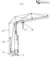
- the telescopic crane shown schematically in FIGS. 1 and 2 has a flat portal 1 with support feet, about the vertical axis 2 of which the rotating stage 3 provided with a conventional rotary drive can be rotated.
- Lateral stands 4 are fastened on the revolving stage, in which the outer tower piece 6 is pivotably mounted about the hinge pin 5. In the erected vertical position of the outer tower section 6, this is connected to the stands 4 or the rotating platform 3 by at least one further bolt connection, not shown.
- the trolley winch 7 and the hoist winch 8 are arranged on the rotating platform 3.
- the trolley rope 9 runs over the cable pulley 10 in the lower region of the outer tower section 6, the cable pulley 11 mounted on the rotating platform 3, the cable pulleys 12, 13 mounted on the outer tower section 6 in the manner shown at the lower corner regions, and on the upper corner region of the outer tower section 6 mounted pulley 14, the cable pulley 15 mounted in the lower corner region of the inner tower piece 21, the cable pulley 16 mounted at the upper end of the inner tower piece 21, the cable pulley 17 at the outer end of the guy support 22, the cable pulley 18 at the outer end of the outer beam 23 of the boom Rope pulley 19 located in the area of the articulated connection 25 between the supports 23, 24 of the jib and is fastened to the trolley 20.
- the cable 25 is fastened to the opposite end of the trolley, the other end of which is fastened at point 26 in the upper region of the inner tower piece 21.
- the rope 25 is guided in the inner tower piece 21 in a loop, a weight 28 being suspended in the loop via a rope pulley 27.
- the inner support part 24 of the boom is articulated in the joint 29.
- the guy supports 31, 32 are pivotally mounted on the axis 30.
- the rear guy cable 34 is fastened at point 33 to the outer end of the guy support 31 pointing to the rear.
- the outer ends of the guy supports 31, 32 are connected to each other by the guy rope 35.
- a guy cable 36 runs to the fixed point in the area of the articulated connection 25 between the support parts 23, 24 and another guy cable 37 via a fixed point at the outer end of the guy support 22 to the fixed point 38 in the area of the outer end of the outer support part.
- the lifting rope 39 runs over the rope pulley 40 of an upper block of a block and tackle, which is connected in the manner shown to the guy rope 34, to the rope pulley 41 of the lower block, which is connected to the rotating platform 3, and from there via the rope pulley 42 in the upper region of the inner tower piece over the rollers of the trolley 20, the role of the crane hook 43 to the fixed point 44 in the area of the outer support part.
- the lock (not shown) between the inner tower section 21 and the outer tower section 6 is released.
- the inner tower piece 21 is now telescoped and locked in the extended position by the locking device 47 with the outer tower piece 6.
- the rear guy cable 34 is tensioned by retracting the lifting cable 29 with the crane hook 43 moved to the stop in the trolley 20, and the boom is thereby opened and swung out. In the pivoted-out position, the lower end of the rear guy cable 34 is then locked with the rotating platform 3.
- the trolley travel and hoisting winches 7, 8 serve to lift the crane hook 43 and to move the cat 20 in the manner shown in FIG. 2.
- the lower block 21 detached from the platform 3, which can be provided with a crane hook, can be used for ballasting the crane.
- the upper bottle 40 is located in the upper region of the lower tower section 6.
- the boom can also be swung out when the inner tower section 21 is retracted or in intermediate positions of the inner tower section. In the intermediate positions, the guy cable 34 is bolted to the turntable 3 with a correspondingly shortened length.
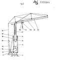
- FIG. 3 differs essentially from the embodiment of FIGS. 1 and 2 only in that the lifting rope 39 via a rope pulley 50 at the upper end of the outer tower piece 6, a rope pulley 51 at the lower end of the inner tower piece 21 and a rope pulley 52 runs at the upper end of the inner tower piece 21 to the rollers 53 of the trolley 20.
- the boom is opened with the inner tower piece retracted or intermediate positions of the inner tower piece, the rope pulley 51 is detached from the inner tower piece 21 and coupled as a bottom block 51 'of a pulley block to a rope 56 running over the rope pulleys 54, 55, the latter other end at point 57 is connected to the guy rope 34. Then, after the inner tower piece 21 has been partially extended and fixed relative to the outer tower piece 6, the boom can be opened via the lifting rope 39. After the boom has been opened, the rear guy cable 34 is fastened to the rotating platform 3 with a correspondingly shortened length.
- the outer support part of the jib can be swung up.
- the inner support part 24 can be swiveled up when the crane hook 43 is moved on the block by actuating the lifting winch 8.
- the pivoting movements of the inner and outer carrier parts can be superimposed on one another.
Landscapes
- Engineering & Computer Science (AREA)
- Mechanical Engineering (AREA)
- Structural Engineering (AREA)
- Transportation (AREA)
- Jib Cranes (AREA)
Abstract
Description
- Die Erfindung betrifft einen Kran mit einem auf einem Oberwagen oder der Drehbühne eines Portals befestigten teleskopierbaren Turm, dessen aus dem Außenturmstück, das zum Aufrichten bei der Montage um einen in seinem unteren Bereich vorgesehenen Gelenkbolzen schwenkbar ist, ausfahrbares Innenturmstück an seinem oberen Ende gelenkig mit dem inneren Trägerteil des Auslegers verbunden ist, an dessen äußerem Ende ein äußeres Trägerteil des Auslegers angelenkt ist, wobei die Trägerteile mit Führungen für die Laufkatze versehen sind, mit zwei im Bereich der Turmspitze angelenkten Abspannstützen, über deren äußeren Festpunkte ein hinteres Abspannseil zu einem Festpunkt auf dem Oberwagen oder Portal verläuft, und mit einer im Bereich der gelenkigen Verbindung der Trägerteile des Auslegers angelenkten Abspannstütze, wobei an dem äußeren Ende der mittleren, im Bereich der Turmspitze angelenkten Abspannstütze zwei weitere Abspannseile befestigt sind, von denen das eine im Bereich der gelenkigen Verbindung der Trägerteile befestigt ist und das andere über einen Festpunkt an dem äußeren Ende der im Bereich zwischen den Trägerteilen angelenkten Abspannstütze zu einem Festpunkt an dem äußeren Ende des äußeren Trägerteils verläuft, und mit einer Katzfahr-und einer Hubwende.
- Aus den DE-OS 33 22 268, 26 14 223, 29 14 265 und 28 31 286 sowie der DE-GMS 80 09 033 bekannte Teleskopkräne dieser und ähnlicher Art benötigen zum Aufrichten des Außenturmstücks mit eingefahrenen Innenturmstück und gegebenenfalls angeklappten Trägerteilen des Auslegers, zum Ausfahren des inneren Turmstücks aus dem äußeren Turmstück und/oder zum Aufklappen und Einschwenken des Auslegers besondere hydraulische Einrichtungen, Teleskopierflaschenzüge und/oder Montagewinden.
- Aufgabe der Erfindung ist es daher, einen Kran mit teleskopierbarem Turm der eingangs angegebenen Art zu schaffen, der sich ohne zusätzliche hydraulische Pressen, Montageflaschenzüge oder Montagewinden nur mit den bereits vorhandenen Hub- und Katzfahrwinden in einfacher Weise aufrichten und montieren läßt.
- Erfindungsgemäß wird diese Aufgabe dadurch gelöst, daß beide Winden im Bereich des Oberwagens oder der Drehbühne angeordnet sind, daß das Katzfahrseil über mindestens eine im Bereich des unteren Endes des Außenturmstücks befestigte Seilrolle, eine im Bereich des oberen Endes des Außenturmstücks befestigte Seilrolle, eine im unteren Bereich des Innenturmstücks gelagerte Seilrolle, im Bereich der Turmspitze des äußeren Endes des äußeren Trägerteils des Auslegers und im Bereich der gelenkigen Verbindung der Trägerteile gelagerte Seilrollen zu einem Festpunkt an der Laufkatze verläuft und daß das Hubseil über Zwischenseilrollen, Umlenkrollen der Laufkatze und die Rolle oder Rollen des Kranhakens zu seinem Festpunkt am äußeren Ende des äußeren Trägerteils verläuft.
- Der erfindungsgemäße Kran läßt sich nur über die Katzfahrwinde aufrichten. Hierzu ist es zunächst erforderlich, daß die Laufkatze an den angeklappten Trägerteilen des Auslegers fixiert ist, so daß das Ende des Katzfahrseils festgelegt ist. Weiterhin ist vor dem Aufrichten des auf die Drehbühne geklappten Außenturmstücks das in diesen eingefahrene Innenturmstück in diesem blockiert. Das Außenturmstück ist in einem Trägerstück der Drehbühne in einem solchen Abstand oberhalb einer Umlenkrolle an seinem unteren Ende schwenkbar gelagert, daß um den lagernden Gelenkbolzen durch Betätigung der Katzfahrwinde ein aufrichtendes Drehmoment erzeugt wird. Sobald das Außenturmstück durch die Katzfahrwinde in seine vertikale Stellung aufgerichtet worden ist, wird es durch mindestens eine weitere Bolzenverbindung fest mit der Drehbühne verbolzt. Anschließend wird die Verriegelung des Innenturmstücks mit dem Außenturmstück aufgehoben, so daß durch erneute Betätigung der Katzfahrwinde das Innenturmstück aus dem Außenturmstück ausgefahren werden kann. In der ausgefahrenen Stellung wird sodann durch Bolzenverbindungen oder dergleichen das Innenturmstück mit dem Außenturmstück verriegelt. Sobald beim Ausfahren des Außenturmstücks die über die Abspannstützen geführten Abspannseile, dessen hinteres Abspannseil mit der Drehbühne verbunden ist, gestrafft werden, werden die angeklappten Trägerteile des Auslegers aufgeklappt und der Ausleger in seine Endstellung verschwenkt. Wird sodann die Verriegelung der Laufkatze mit dem entsprechenden Trägerteil aufgehoben, läßt sich über die Katzfahrwinde die Laufkatze in Richtung auf das äußere Auslegerende verfahren, so daß nur noch Einrichtungen vorgesehen werden müssen, um die Laufkatze auch in entgegengesetzter Richtung verfahren zu können. Diese Einrichtung kann darin bestehen, daß die Laufkatze über ein Seil, das im Bereich des Turms eine Schlaufe bildet, in die ein Gewicht eingehängt ist, mit der Turmspitze verbunden ist. Das Gewicht bewirkt, daß auf die Laufkatze immer ein Zug in Richtung auf den Turm wirkt, so daß sie durch entsprechendes Ablassen des Katzfahrseils von der Katzfahrwinde in Richtung auf den Turm verfahren wird. Die gleiche Wirkung kann auch erzielt werden, wenn der Ausleger in der montierten Stellung nach oben hin über die Horizontale hinaus geschwenkt ist, also mit der Horizontalen einen spitzen Winkel bildet.
- Es ist auch denkbar, den Kran in der beschriebenen Weise über das Hubseil und die Hubwinde aufzurichten, wobei sDdann das Hubseil entsprechend einzuscheren ist.
- Nach einer erfinderischen Ausgestaltung ist vorgesehen, daß das Hubseil über an dem hinteren Abspannseil und an der Drehbühne gelagerte Seilrollen flaschenzugartig eingeschert ist. Diese Ausgestaltung ermöglicht es, das hintere Abspannseil über die Hubwinde zu spannen und dadurch die Trägerteile des Auslegers aufzuklappen und auszuschwenken. Nach dem Ausschwenken des Auslegers in die montierte Stellung wird das Abspannseil straff mit der Drehbühne verbunden, so daß der Flaschenzug entlastet wird oder auf diesen ganz verzichtet werden kann. Da das Aufklappen und Ausschwenken des Auslegers unabhängig von dem Ausfahren des Innenturmstücks erfolgen kann, kann der Ausleger auch bei in das Außenturmstück eingefahrenem Innenturmstück oder aber auch in allen Zwischenstellungen ausgestellt werden.
- Zum Ausfahren des Innenturmstücks und gegebenenfalls gleichzeitigem Aufklappen des Auslegers kann statt der Laufkatze auch das in der Seilschlaufe hängende Gewicht in vorbestimmten Stellungen blockiert werden.
- Nach einer weiteren erfinderischen Ausgestaltung ist das Hubseil über am oberen Ende des Außenturmstücks, am unteren Ende des Innenturmstücks und im Bereich der Turmspitze gelagerte Seilrollen zu den Seilrollen der Laufkatze geführt. Nach dieser Ausgestaltung erfolgt nach der beschriebenen Aufrichtung des unteren Aussenturmstücks das Außenteleskopieren des Innenturmstücks über das Hubseil über die Hubwinde, wobei der Kranhaken auf Anschlag gegen die Laufkatze gefahren ist und wobei beim Ausfahren gleichzeitig auch der Ausleger aufgeklappt und ausgeschwenkt wird, wobei die Katzfahrwinde zunächst nicht betätigt zu werden braucht, weil die durch das Ausfahren gewonnene Seilverlängerung des Katzfahrseils dieses im Bereich des Auslegers verlängert und dadurch das Aufklappen und Ausschwenken des Auslegers ermöglicht. Erforderliche Korrekturen können durch entsprechende Betätigung der Katzfahrwinde vorgenommen werden.
- Nach einer weiteren Ausgestaltung ist vorgesehen, daß die an dem unteren Ende des Innenturmstücks befestigte Seilrolle lösbar und als Unterflasche eines Flaschenzugs an ein Seil befestigbar ist, das über Umlenkrollen läuft und dessen anderes Ende mit dem hinteren Abspannseil verbunden ist. Nach dieser Ausgestaltung kann in der eingefahrenen Stellung des inneren Turmstücks oder in Zwischenstellungen der Ausleger durch Betätigung der Hubwinde aufgeklappt und ausgeschwenkt werden.
- Beim Aufrichten des äußeren Turmstücks kann in weiterer Ausgestaltung der Erfindung nach der ersten Ausführungsform die Seilrolle von der Drehbühne gelöst und als Unterflasche mit einem Kranhaken zur Ballastierung des Krans versehen sein. Zur Ballastierung läßt sich das äußere Turmstück über die Katzfahrwinde wippen und zur Ballastierung läßt sich die mit einem Kranhaken versehene Unterflasche über die Hubwinde heben und senken.
- Ausführungsbeispiele der Erfindung werden nachstehend anhand der Zeichnung näher erläutert. In dieser zeigt
- Fig. 1 eine Seitenansicht der ersten Ausführungsform des Teleskopkrans während des Aufrichtens in schematischer Darstellung,
- Fig. 2 den Teleskopkran nach Fig. 1 in seiner montierten Stellung und
- Fig. 3 eine der Fig. 1 entsprechende Darstellung einer zweiten Ausführungsform eines Teleskopkrans.
- Der in den Fig. 1 und 2 schematisch dargestellte Teleskopkran weist ein flaches Portal 1 mit Stützfüßen auf, um dessen vertikale Achse 2 die mit einem üblichen Drehantrieb versehene Drehbühne 3 drehbar ist. Auf der Drehbühne sind seitliche Ständer 4 befestigt, in denen um den Gelenkbolzen 5 das Außenturmstück 6 schwenkbar gelagert ist. In der aufgerichteten vertikalen Stellung des Außenturmstücks 6 wird dieses durch mindestens eine weitere nicht dargestellte Bolzenverbindung mit den Ständern 4 oder der Drehbühne 3 verbunden. i
- Auf der Drehbühne 3 sind die Katzfahrwinde 7 und die Hubwinde 8 angeordnet. Das Katzfahrseil 9 läuft über die Seilrolle 10 im unteren Bereich des Außenturmstücks 6, die auf der Drehbühne 3 gelagerte Seilrolle 11, die an den unteren Eckbereichen in der dargestellten Weise an dem Außenturmstück 6 gelagerten Seilrollen 12, 13, die an dem oberen Eckbereich des Außenturmstücks 6 gelagerte Seilrolle 14, die im unteren Eckbereich des Innenturmstücks 21 gelagerte Seilrolle 15, die am oberen Ende des Innenturmstücks 21 gelagerte Seilrolle 16, die Seilrolle 17 am äußeren Ende der Abspannstütze 22, die Seilrolle 18 am äußeren Ende des äußeren Trägers 23 des Auslegers, die im Bereich der gelenkigen Verbindung 25 zwischen den Trägern 23, 24 des Auslegers befindliche Seilrolle 19 und ist an der Laufkatze 20 befestigt. An dem gegenüberliegenden Ende der Laufkatze ist das Seil 25 befestigt, dessen anderes Ende im Punkt 26 im oberen Bereich des Innenturmstücks 21 befestigt ist. Das Seil 25 ist in dem Innenturmstück 21 in einer Schlaufe geführt, wobei in die Schlaufe über eine Seilrolle 27 ein Gewicht 28 eingehängt ist.
- An das obere Ende des Innenturmstücks 21 ist in dem Gelenk 29 das innere Trägerteil 24 des Auslegers angelenkt. Am inneren Ende des inneren Trägerteils 24 sind auf der Achse 30 die Abspannstützen 31, 32 schwenkbar gelagert. An dem äußeren Ende der nach hinten weisenden Abspannstütze 31 ist im Punkt 33 das hintere Abspannseil 34 befestigt. Die äußeren Enden der Abspannstützen 31, 32 sind durch das Abspannseil 35 miteinander verbunden. Von dem äußeren Ende der Abspannstütze 32 verläuft ein Abspannseil 36 zu dem Festpunkt im Bereich der gelenkigen Verbindung 25 zwischen den Trägerteilen 23, 24 und ein weiteres Abspannseil 37 über einen Festpunkt am äußeren Ende der Abspannstütze 22 zu dem Festpunkt 38 im Bereich des äußeren Endes des äußeren Trägerteils.
- Das Hubseil 39 verläuft über die Seilrolle 40 einer Oberflasche eines Flaschenzuges, die in der dargestellten Weise mit dem Abspannseil 34 verbunden ist, zu der Seilrolle 41 der Unterflasche, die mit der Drehbühne 3 verbunden ist, und von dieser über die Seilrolle 42 im oberen Bereich des Innenturmstücks über die Rollen der Laufkatze 20, die Rolle des Kranhakens 43 zu dem Festpunkt 44 im Bereich des äußeren Trägerteils.
- Nachdem der Kran in der aus Fig. 2 ersichtlichen Weise vollständig aufgerichtet worden ist, wird das untere Ende des hinteren Abspannseils 34 in der Öse 45 an der Drehbühne 3 befestigt.
- Das Aufrichten des Krans geschieht in folgender Weise:
- Zunächst liegt das Außenturmstück 6 mit eingeschobenem Innenturmstück 21 und angeklappten Trägerteilen 23, 24 des Auslegers in etwa horizontaler Stellung auf der Drehbühne 3. Das Katzfahrseil 9 ist durch Verriegelung des Gewichts 28 durch die Verriegelungseinrichtung 46 mit dem Innenturmstück 21 verriegelt. Durch Betätigung der Katzfahrwinde 7 wird sodann das Außenturmstück 6 in die dargestellte vertikale Stellung um den Bolzen 5 verschwenkt und in dieser Stellung verriegelt. Beim Aufrichten wird der Hebelarm zwischen dem Gelenkbolzen 5 und den Seilrollen 12 und/ oder 13 wirksam.
- Nach dem Aufrichten des Außenturmstücks 6 wird die nicht dargestellte Verriegelung zwischen dem Innenturmstück 21 und dem Außenturmstück 6 gelöst. Durch weitere Betätigung der Katzfahrwinde 7 wird nun das Innenturmstück 21 austeleskopiert und in der ausgefahrenen Stellung durch die Riegeleinrichtung 47 mit dem Außenturmstück 6 verriegelt. Beim oder nach dem Ausfahren des Innenturmstücks 21 wird durch Einfahren des Hubseils 29 bei auf Anschlag in der Laufkatze 20 gefahrenem Kranhaken 43 das hintere Abspannseil 34 gespannt und dadurch der Ausleger aufgeklappt und ausgeschwenkt. In der ausgeschwenkten Stellung wird sodann das untere Ende des hinteren Abspannseils 34 mit der Drehbühne 3 verriegelt.
- Nach der Montage dienen die Katzfahr- und Hubwinden 7, 8 in der aus Fig. 2 ersichtlichen Weise dem Heben des Kranhakens 43 und dem Verfahren der Katze 20.
- Werden bei der Montage die Trägerteile 23, 24 des Auslegers durch Straffen des hinteren Abspannseils 34 über das Hubseil 39 aufgeklappt, muß über die Katzfahrwinde 37 so viel Seil nachgelassen werden, daß das Aufspannen ermöglicht wird.
- Während des Aufrichtens des Außenturmstücks 9 kann die von der Plattform 3 gelöste Unterflasche 21, die mit einen Kranhaken versehen sein kann, zum Ballastieren des Krans benutzt werden. In der Ballastierstellung befindet sich die Oberflasche 40 im oberen Bereich des unteren Turmstücks 6.
- Der Ausleger kann auch bei eingefahrenem inneren Turmstück 21 oder in Zwischenstellungen des inneren Turmstücks ausgeschwenkt werden. In den Zwischenstellungen wird das Abspannseil 34 mit entsprechend verkürzter Länge an der Drehbühne 3 verbolzt.
- Das Ausführungsbeispiel nach Fig. 3 unterscheidet sich im wesentlichen von dem Ausführungsbeispiel nach den Fig. 1 und 2 nur dadurch, daß das Hubseil 39 über eine Seilrolle 50 am oberen Ende des Außenturmstücks 6, eine Seilrolle 51 am unteren Ende des Innenturmstücks 21 und einer Seilrolle 52 am oberen Ende des Innenturmstücks 21 zu den Rollen 53 der Laufkatze 20 läuft. Infolge dieser geänderten Führung des Hubseils ergibt sich folgende geänderte Art der Aufstellung des Krans: Nach dem Aufrichten des Außenturmstücks 6 mit der Katzfahrwinde 7 als Wippwinde und Verriegeln mit der Drehbühne 3 wird das Innenturmstück 21 bei auf Block gefahrenem Kranhaken 43 durch die Hubwinde 8 und das Hubseil 9 austeleskopiert, wobei das hintere Abspannseil 34 gestrafft und dadurch die Trägerteile 23, 24 des Auslegers aufgeklappt werden. Bei dem Austeleskopieren des Innenturmstücks 21 wird durch Annäherung der Seilrollen 14, 15 Seillänge gewonnen, die ein Aufklappen des Auslegers ermöglicht.
- Soll bei der Ausführungsform nach Fig. 3 der Ausleger bei eingefahrenem Innenturmstück oder Zwischenstellungen des Innenturmstücks aufgeklappt werden, wird die Seilrolle 51 von dem Innenturmstück 21 gelöst und als Unterflasche 51' eines Flaschenzugs an ein über die Seilrollen 54, 55 laufendes Seil 56 angekuppelt, dessen anderes Ende im Punkt 57 mit dem Abspannseil 34 verbunden ist. Über das Hubseil 39 läßt sich sodann, nachdem gegebenenfalls das Innenturmstück 21 teilweise ausgefahren und relativ zu dem Außenturmstück 6 fixiert ist, der Ausleger aufklappen. Nach dem Aufklappen des Auslegers wird das hintere Abspannseil 34 mit entsprechend verkürzter Länge an der Drehbühne 3 befestigt.
- Bei der Ausführungsform nach den Fig. 1 und 2 läßt sich nach Fixieren der Laufkatze oder des Gewichts mit der Katzfahrwinde das äußere Trägerteil des Auslegers hochschwenken. Der innere Trägerteil 24 läßt sich bei auf Block gefahrenem Kranhaken 43 durch Betätigung der Hubwinde 8 hochschwenken. Durch Betätigung beider Winden können die Schwenkbewegungen der inneren und äußeren Trägerteile einander überlagert werden.
Claims (7)
dadurch gekennzeichnet,
Priority Applications (1)
| Application Number | Priority Date | Filing Date | Title |
|---|---|---|---|
| AT84114818T ATE42942T1 (de) | 1984-01-13 | 1984-12-05 | Kran mit teleskopierbarem turm. |
Applications Claiming Priority (2)
| Application Number | Priority Date | Filing Date | Title |
|---|---|---|---|
| DE3401094 | 1984-01-13 | ||
| DE3401094A DE3401094C2 (de) | 1984-01-13 | 1984-01-13 | Kran mit teleskopierbarem Turm |
Publications (3)
| Publication Number | Publication Date |
|---|---|
| EP0150344A2 true EP0150344A2 (de) | 1985-08-07 |
| EP0150344A3 EP0150344A3 (en) | 1987-09-09 |
| EP0150344B1 EP0150344B1 (de) | 1989-05-10 |
Family
ID=6224943
Family Applications (1)
| Application Number | Title | Priority Date | Filing Date |
|---|---|---|---|
| EP84114818A Expired EP0150344B1 (de) | 1984-01-13 | 1984-12-05 | Kran mit teleskopierbarem Turm |
Country Status (3)
| Country | Link |
|---|---|
| EP (1) | EP0150344B1 (de) |
| AT (1) | ATE42942T1 (de) |
| DE (2) | DE3401094C2 (de) |
Cited By (1)
| Publication number | Priority date | Publication date | Assignee | Title |
|---|---|---|---|---|
| DE3719986A1 (de) * | 1987-06-15 | 1988-12-29 | Liebherr Werk Biberach Gmbh | Turmdrehkran |
Families Citing this family (2)
| Publication number | Priority date | Publication date | Assignee | Title |
|---|---|---|---|---|
| DE3422146A1 (de) * | 1984-02-21 | 1985-08-22 | Liebherr-Werk Bischofshofen GmbH, Bischofshofen | Kran mit teleskopierbarem turm |
| CN101962156B (zh) * | 2010-10-18 | 2012-04-04 | 南京工业大学 | 一种可折叠快装塔机 |
Family Cites Families (10)
| Publication number | Priority date | Publication date | Assignee | Title |
|---|---|---|---|---|
| DE976018C (de) * | 1953-05-21 | 1963-01-17 | Hans Tax | Turmdrehkran mit einem um eine waagerechte Achse des Kranwagens aufrichtbaren Turm |
| AT294370B (de) * | 1969-10-22 | 1971-11-25 | Wetzel Kg | Turmdrehkran |
| FR2138254B2 (de) * | 1971-05-21 | 1975-10-10 | Esteve Andre | |
| FR2236772A1 (en) * | 1973-07-03 | 1975-02-07 | Rock Sa | Tower crane erection system - has hoist rope reeved round pulley block attached to erection winch rope |
| FR2398017A1 (fr) * | 1977-07-22 | 1979-02-16 | Acme | Perfectionnements aux systemes pour le repliage ou le deploiement de la fleche articulee d'une grue a mat telescopique |
| FR2422581A1 (fr) * | 1978-04-10 | 1979-11-09 | Potain Sa | Systeme pour le depliage loin du sol de la fleche d'une grue telescopique |
| DE2944473A1 (de) * | 1979-11-03 | 1981-05-14 | Cadillon S.A., Charolles | Kran sowie verfahren zu seiner bedienung |
| DE3005984C2 (de) * | 1980-02-18 | 1985-04-11 | Pekazett Baumaschinen GmbH, 6660 Zweibrücken | Turmdrehkran |
| DE8009033U1 (de) * | 1980-04-01 | 1980-09-04 | Liebherr-Werk Bischofshofen Gmbh, Bischofshofen (Oesterreich) | Kran mit teleskopturm |
| DE3229949C1 (de) * | 1982-08-12 | 1983-11-17 | Peiner Hebe- Und Transportsysteme Gmbh, 5500 Trier | Turmkran |
-
1984
- 1984-01-13 DE DE3401094A patent/DE3401094C2/de not_active Expired
- 1984-12-05 EP EP84114818A patent/EP0150344B1/de not_active Expired
- 1984-12-05 AT AT84114818T patent/ATE42942T1/de not_active IP Right Cessation
- 1984-12-05 DE DE8484114818T patent/DE3478102D1/de not_active Expired
Cited By (1)
| Publication number | Priority date | Publication date | Assignee | Title |
|---|---|---|---|---|
| DE3719986A1 (de) * | 1987-06-15 | 1988-12-29 | Liebherr Werk Biberach Gmbh | Turmdrehkran |
Also Published As
| Publication number | Publication date |
|---|---|
| DE3401094A1 (de) | 1985-07-25 |
| DE3478102D1 (en) | 1989-06-15 |
| ATE42942T1 (de) | 1989-05-15 |
| EP0150344A3 (en) | 1987-09-09 |
| EP0150344B1 (de) | 1989-05-10 |
| DE3401094C2 (de) | 1986-12-18 |
Similar Documents
| Publication | Publication Date | Title |
|---|---|---|
| EP1894883B1 (de) | Fahrzeugkran | |
| EP0779236A1 (de) | Fahrzeugkran | |
| EP0132572B1 (de) | Kran mit teleskopierbarem Turm | |
| DE9316113U1 (de) | Turmdrehkran | |
| EP0624542A2 (de) | Kran mit teleskopierbarem Turm | |
| DE3207443A1 (de) | Drehkran | |
| DE19730361A1 (de) | Fahrzeugkran | |
| EP0150344B1 (de) | Kran mit teleskopierbarem Turm | |
| DE3340845C1 (de) | Gittermastkran mit zerlegbarem Hauptausleger | |
| DE2300643A1 (de) | Fahrzeugkran | |
| EP0152562A2 (de) | Kran mit teleskopierbarem Turm | |
| EP0296383A1 (de) | Turmdrehkran | |
| DE3315888A1 (de) | Kran zum umschlagen von guetern von einem schiff auf ein anderes | |
| DE4221915A1 (de) | Untendrehender Turmdrehkran | |
| DE20314561U1 (de) | Kran | |
| DE8205723U1 (de) | Drehkran | |
| EP0997427B1 (de) | Unten drehender Turmdrehkran | |
| DE2101842C (de) | Turmkran | |
| DE29916410U1 (de) | Gelenkig miteinander verbundene, im Querschnitt dreieckige Gitterträger | |
| EP1084983A1 (de) | Turmdrehkran | |
| AT526450A2 (de) | Fahrzeugkran mit einem lösbaren Anbau-Oberwagen und Rüstverfahren hierzu | |
| DE2300579C3 (de) | Kran mit zusammenklappbarem Mast und Ausleger | |
| DE9214587U1 (de) | Arbeitsbühne | |
| DE1057307B (de) | Hochbaukran mit umlegbarem Turm und Nadelausleger | |
| DE9321390U1 (de) | Kran mit teleskopierbarem Turm |
Legal Events
| Date | Code | Title | Description |
|---|---|---|---|
| PUAI | Public reference made under article 153(3) epc to a published international application that has entered the european phase |
Free format text: ORIGINAL CODE: 0009012 |
|
| AK | Designated contracting states |
Designated state(s): AT BE CH DE FR GB IT LI NL |
|
| PUAL | Search report despatched |
Free format text: ORIGINAL CODE: 0009013 |
|
| AK | Designated contracting states |
Kind code of ref document: A3 Designated state(s): AT BE CH DE FR GB IT LI NL |
|
| 17P | Request for examination filed |
Effective date: 19871030 |
|
| 17Q | First examination report despatched |
Effective date: 19880413 |
|
| GRAA | (expected) grant |
Free format text: ORIGINAL CODE: 0009210 |
|
| AK | Designated contracting states |
Kind code of ref document: B1 Designated state(s): AT BE CH DE FR GB IT LI NL |
|
| PG25 | Lapsed in a contracting state [announced via postgrant information from national office to epo] |
Ref country code: NL Effective date: 19890510 Ref country code: IT Free format text: LAPSE BECAUSE OF FAILURE TO SUBMIT A TRANSLATION OF THE DESCRIPTION OR TO PAY THE FEE WITHIN THE PRESCRIBED TIME-LIMIT;WARNING: LAPSES OF ITALIAN PATENTS WITH EFFECTIVE DATE BEFORE 2007 MAY HAVE OCCURRED AT ANY TIME BEFORE 2007. THE CORRECT EFFECTIVE DATE MAY BE DIFFERENT FROM THE ONE RECORDED. Effective date: 19890510 Ref country code: GB Effective date: 19890510 Ref country code: BE Effective date: 19890510 |
|
| REF | Corresponds to: |
Ref document number: 42942 Country of ref document: AT Date of ref document: 19890515 Kind code of ref document: T |
|
| REF | Corresponds to: |
Ref document number: 3478102 Country of ref document: DE Date of ref document: 19890615 |
|
| ET | Fr: translation filed | ||
| NLV1 | Nl: lapsed or annulled due to failure to fulfill the requirements of art. 29p and 29m of the patents act | ||
| GBV | Gb: ep patent (uk) treated as always having been void in accordance with gb section 77(7)/1977 [no translation filed] | ||
| PG25 | Lapsed in a contracting state [announced via postgrant information from national office to epo] |
Ref country code: AT Effective date: 19891205 |
|
| PG25 | Lapsed in a contracting state [announced via postgrant information from national office to epo] |
Ref country code: LI Effective date: 19891231 Ref country code: CH Effective date: 19891231 |
|
| PLBE | No opposition filed within time limit |
Free format text: ORIGINAL CODE: 0009261 |
|
| STAA | Information on the status of an ep patent application or granted ep patent |
Free format text: STATUS: NO OPPOSITION FILED WITHIN TIME LIMIT |
|
| 26N | No opposition filed | ||
| REG | Reference to a national code |
Ref country code: CH Ref legal event code: PL |
|
| PGFP | Annual fee paid to national office [announced via postgrant information from national office to epo] |
Ref country code: FR Payment date: 19941208 Year of fee payment: 11 |
|
| PGFP | Annual fee paid to national office [announced via postgrant information from national office to epo] |
Ref country code: DE Payment date: 19950125 Year of fee payment: 11 |
|
| PG25 | Lapsed in a contracting state [announced via postgrant information from national office to epo] |
Ref country code: FR Effective date: 19960830 |
|
| PG25 | Lapsed in a contracting state [announced via postgrant information from national office to epo] |
Ref country code: DE Effective date: 19960903 |
|
| REG | Reference to a national code |
Ref country code: FR Ref legal event code: ST |