EP0147784A2 - Dispositif pour nettoyer des conduites, en particulier des conduites de tirage - Google Patents
Dispositif pour nettoyer des conduites, en particulier des conduites de tirage Download PDFInfo
- Publication number
- EP0147784A2 EP0147784A2 EP84115793A EP84115793A EP0147784A2 EP 0147784 A2 EP0147784 A2 EP 0147784A2 EP 84115793 A EP84115793 A EP 84115793A EP 84115793 A EP84115793 A EP 84115793A EP 0147784 A2 EP0147784 A2 EP 0147784A2
- Authority
- EP
- European Patent Office
- Prior art keywords
- valve
- housing
- intermediate housing
- cleaning
- coupling
- Prior art date
- Legal status (The legal status is an assumption and is not a legal conclusion. Google has not performed a legal analysis and makes no representation as to the accuracy of the status listed.)
- Granted
Links
- 238000004140 cleaning Methods 0.000 title claims abstract description 55
- 238000010079 rubber tapping Methods 0.000 title 1
- 239000007788 liquid Substances 0.000 claims abstract description 19
- 238000010168 coupling process Methods 0.000 claims description 34
- 230000008878 coupling Effects 0.000 claims description 33
- 238000005859 coupling reaction Methods 0.000 claims description 33
- 230000004323 axial length Effects 0.000 claims description 3
- 230000000284 resting effect Effects 0.000 claims description 2
- 239000012459 cleaning agent Substances 0.000 abstract 4
- 235000013405 beer Nutrition 0.000 description 5
- XLYOFNOQVPJJNP-UHFFFAOYSA-N water Substances O XLYOFNOQVPJJNP-UHFFFAOYSA-N 0.000 description 3
- 244000052616 bacterial pathogen Species 0.000 description 2
- 235000013361 beverage Nutrition 0.000 description 2
- 238000010276 construction Methods 0.000 description 2
- 238000000034 method Methods 0.000 description 2
- 239000002245 particle Substances 0.000 description 2
- 238000007789 sealing Methods 0.000 description 2
- 239000003570 air Substances 0.000 description 1
- 239000012080 ambient air Substances 0.000 description 1
- 238000006073 displacement reaction Methods 0.000 description 1
- 239000011521 glass Substances 0.000 description 1
- 238000003780 insertion Methods 0.000 description 1
- 230000037431 insertion Effects 0.000 description 1
- 235000019520 non-alcoholic beverage Nutrition 0.000 description 1
- 229920003023 plastic Polymers 0.000 description 1
- 230000000717 retained effect Effects 0.000 description 1
- 239000010802 sludge Substances 0.000 description 1
- 230000008961 swelling Effects 0.000 description 1
Images
Classifications
-
- B—PERFORMING OPERATIONS; TRANSPORTING
- B08—CLEANING
- B08B—CLEANING IN GENERAL; PREVENTION OF FOULING IN GENERAL
- B08B9/00—Cleaning hollow articles by methods or apparatus specially adapted thereto
- B08B9/02—Cleaning pipes or tubes or systems of pipes or tubes
- B08B9/027—Cleaning the internal surfaces; Removal of blockages
- B08B9/04—Cleaning the internal surfaces; Removal of blockages using cleaning devices introduced into and moved along the pipes
- B08B9/053—Cleaning the internal surfaces; Removal of blockages using cleaning devices introduced into and moved along the pipes moved along the pipes by a fluid, e.g. by fluid pressure or by suction
- B08B9/055—Cleaning the internal surfaces; Removal of blockages using cleaning devices introduced into and moved along the pipes moved along the pipes by a fluid, e.g. by fluid pressure or by suction the cleaning devices conforming to, or being conformable to, substantially the same cross-section of the pipes, e.g. pigs or moles
- B08B9/0551—Control mechanisms therefor
-
- B—PERFORMING OPERATIONS; TRANSPORTING
- B08—CLEANING
- B08B—CLEANING IN GENERAL; PREVENTION OF FOULING IN GENERAL
- B08B9/00—Cleaning hollow articles by methods or apparatus specially adapted thereto
- B08B9/02—Cleaning pipes or tubes or systems of pipes or tubes
- B08B9/027—Cleaning the internal surfaces; Removal of blockages
- B08B9/04—Cleaning the internal surfaces; Removal of blockages using cleaning devices introduced into and moved along the pipes
- B08B9/053—Cleaning the internal surfaces; Removal of blockages using cleaning devices introduced into and moved along the pipes moved along the pipes by a fluid, e.g. by fluid pressure or by suction
- B08B9/057—Cleaning the internal surfaces; Removal of blockages using cleaning devices introduced into and moved along the pipes moved along the pipes by a fluid, e.g. by fluid pressure or by suction the cleaning devices being entrained discrete elements, e.g. balls, grinding elements, brushes
Definitions
- the invention relates to a device for cleaning pipelines, in particular dispensing lines, by means of cleaning bodies, with a four-way changeover valve, which optionally connects an inlet connection for the supply of cleaning liquid with one of two working connections and the other working connection with a drain connection, whereby an intermediate housing extends between the valve housing and at least one of the working connections, which leads in particular from a small cross section corresponding to the working connection to a larger cross section.
- a two-part intermediate housing which consists of a glass cylinder and a flange that supports the working connection.
- This flange is with several screws; connected to a flange on the valve housing.
- the working connection has an external thread onto which the screw cap of a coupling which can be released by hand can be screwed, with the aid of which a connecting line can be coupled.
- the cleaning bodies designed as sponges have a size adapted to the connecting line and the beer line.
- the cross-section of the working connection corresponds to the line cross-section.
- the sponge-like cleaning bodies have to be removed from the interior of the intermediate housing after each uncoupling of the connecting line and brought to another storage location. If they were left in the intermediate housing, they would dry out after the water had run off and could absorb germs from the ambient air. Since the removal must take place through the work connection, a special gripping tool is required depending on the swelling condition of the cleaning bodies. It is just as difficult to remove dirt particles that have been retained by the sieve plate on the piston. Another disadvantage is that only a pipeline of the same diameter can be cleaned with a changeover valve, because the working connection only fits for a certain line cross section. However, since tap lines of different cross-sections are often available, for example beer lines with a diameter of 7 to 12 mm and lines for non-alcoholic beverages with a diameter of 5 mm an appropriate number of changeover valves.
- the invention has for its object to provide a cleaning device of the type described in the introduction, in which the problems associated with the removal of the cleaning bodies from the intermediate housing are reduced or eliminated.
- the intermediate housing forms a storage container for cleaning bodies, which has a closable filling opening for filling a storage liquid in its interior and has a lock for maintaining a liquid level lying above the resting cleaning bodies.
- the intermediate housing is designed as a storage container in which the cleaning bodies can be permanently in a storage liquid, that is to say they are sealed off from the air.
- the storage liquid can be sterile, so that the cleaning bodies cannot carry any germs into the piping the next time they are used.
- the cleaning bodies are located in the immediate vicinity of the changeover valve and therefore cannot be lost.
- the cleaning bodies are immediately taken into the connecting lines by the cleaning liquid.
- the closure of the filling opening can preferably be opened by hand.
- the intermediate housing is connected to the valve housing in the region of its larger cross section via a coupling which can be released by hand and has a correspondingly large inner diameter.
- the removal of the cleaning bodies from the intermediate housing is facilitated in that the interior thereof is very conveniently accessible via a large opening cross section.
- the cleaning bodies can simply be removed or poured out by tipping over.
- a coupling that can be released by hand that is to say without a tool, in the region of the larger cross section of the intermediate housing, it is ensured that the interior can be made quickly accessible.
- the intermediate housing forms an adapter head connected to the connecting line, which can be handled much better during the coupling process than a small end section of the connecting line. Since the adapter head can be permanently assigned to the respective connection line, each connection line, regardless of its diameter, can be connected to one and the same changeover valve.
- the cleaning device is therefore very versatile and easy to use.
- Both alternatives can also be used in a common construction, in which the intermediate housing is arranged under the valve housing, its opening surrounded by the coupling forms the filling opening and a shut-off valve is provided in the area of the working connection.
- the shut-off valve When the shut-off valve is closed and the intermediate housing is uncoupled, the cleaning bodies can be stored in the intermediate housing and the storage liquid can be filled in through the opening in the coupling area to such an extent that the cleaning bodies are covered.
- the filling opening is closed by connection to the valve housing by means of the coupling. In the next cleaning process, the cleaning bodies are therefore taken automatically after the shut-off valve has been opened and cleaning liquid has been supplied.
- the intermediate housing is connected directly to the valve housing via the coupling, which can be released by hand, and the inner diameter the coupling corresponds at least to the diameter of the effective piston face.
- At least two sets of adapter heads formed by intermediate housings can be assigned to a valve housing, the working connections of which have different diameters, but are otherwise identical to one another.
- connecting lines with a diameter of 7 mm and those with a diameter of 10 mm can be available in a beverage cellar, each of which is provided with corresponding adapter heads. Then both 7 mm pipes and 10 mm pipes can be cleaned with one and the same switching valve.
- the coupling which can be released by hand is particularly advantageous as a quick coupling which can be closed and / or released by a relative movement of the intermediate housing with respect to the valve housing.
- the intermediate housing can be gripped well, so that the quick coupling can be actuated safely. This is much more convenient than operating the small screw cap in the known releasable coupling.
- a quick coupling reference is made to a plug-in coupling, such as those with smaller dimensions for garden sludge Chen is common, with the coupling being closed by axial insertion and the release being effected by axial displacement of a locking ring.
- the quick coupling can be closed or released in the manner of a bayonet lock by rotating and axially displacing the intermediate housing relative to the valve housing. In this case, only the intermediate housing needs to be moved both for closing and for releasing.
- valve housing has a flange which has cutouts which are offset in the circumferential direction
- intermediate housing has matching hooks which are open in the circumferential direction and which embrace the remaining flange sections through the cutouts.
- the intermediate housing is particularly advantageously formed in one piece with the working connection. In particular, no intermediate fastenings interfere when the intermediate housing is gripped by hand.
- the clutch which can be released by hand, should be located near the piston end of the changeover valve. This gives the adapter head a relatively large axial length, which makes handling easier.
- the intermediate housing should have an axial length of at least 10 cm.
- the intermediate housing has longitudinal ribs on the outer circumference. This can the required torque can be applied particularly easily by hand.
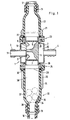
- a changeover valve 1 has a valve housing 2 with an inlet connection 3 and an outlet connection 4.
- a piston 5 is displaceable in the housing, the end faces of which are formed by sieve plates 6 and 7, respectively. It has two valve openings 8 and 9.
- the valve opening 8 is in the illustrated piston position with an annular space 10 and therefore with the drain port 4 in connection.
- the valve opening 9 is connected to the channel 11 in the interior of the inlet connection 3.
- the piston has a longitudinal groove 12, the ends of which serve as limit stops for the axial movement of the piston 5 and the flat bottom of which is opposite the end face of the inlet connection 3.
- the intermediate housing 13 and 14 made of transparent plastic are connected to the valve housing 2, which are made in one piece with a working connection 15 and 16 respectively. They are constantly connected to a corresponding connecting line 17 or 18, for example by means of a clamp 18 or 19 (Fig. 2). They therefore each form a matching head for connection to the valve housing 2 for these connecting lines.
- the intermediate housings are provided on the outside with longitudinal ribs 21 and 22 and have a length of more than 10 cm.
- the upper intermediate housing 13 is detachably connected to the valve housing 2 by means of a quick coupling 23, the lower intermediate housing 14 by means of a quick coupling 24 without tools.
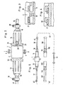
- the expansion of this coupling which operates in the manner of a bayonet lock, is shown in FIGS. 2 to 4.
- a radial flange 25 is provided on the valve housing 2, which has individual cutouts 26 offset in the circumferential direction, so that flange sections 27 remain.
- the intermediate housing 14 has hooks 28 which fit through the cutouts 26 and are open in the circumferential direction. As a result, the intermediate housing 14 can be brought from the open position in FIG. 3 by a short axial movement and a subsequent brief rotary movement into the coupling position of FIG. 4.
- the coupling is released in the same way by turning back and moving axially back.
- the quick coupling 23 is constructed in the same way.
- the piston 5 is sealed against the housing 2 by two sealing rings 29 and 30. Furthermore, when tightening the coupling gen 23 and 24 sealing rings 31 and 32 pressed against an annular surface of the valve housing 2.
- the lower intermediate housing 14 in FIG. 1 has a shut-off valve 33 with a valve flap 35 which can be pivoted about an axis 34 and which can be pivoted into the position 36 shown in broken lines.
- the shut-off valve 33 When the shut-off valve 33 is closed, the usual cleaning bodies 37, which are in the form of sponge balls, can be brought into the interior 38 of the intermediate housing 14 and stored there.
- the intermediate housing 14 is detached from the valve housing 2 and a sterile storage liquid is poured in through the resulting large opening 39 to a level such that the cleaning bodies 37 are completely covered.
- the shut-off valve 33 only needs to be opened.
- the cleaning bodies 37 are then automatically taken into the circuit by the cleaning liquid.
- the intermediate housing 14 therefore serves as a storage container for the cleaning bodies.
- the changeover valve is easily accessible.
- the piston can be moved into the correct starting position by hand.
- the interior of the intermediate housing 13 and 14 can also be easily cleaned.
- the cleaning bodies 37 can be gripped comfortably or removed by tipping over.
- the connecting lines 17 and 18 each have a coupling 40 or 41 at their free end, via which they can be connected to a dispensing line 42 or 43, respectively.
- the other two ends of the dispensing lines are connected to one another via a hose section 44, so that a pipeline circuit results.
- the hose section 44 can be arranged between two taps on the bar table. 5
- a first set of intermediate housings 13 and 14 serving as adapter heads with associated connecting lines 17 and 18
- a second set of intermediate housings 113 and 114 serving as adapter heads with associated connecting lines 117 and 118 are assigned in changeover valve 1.
- the connecting lines 117 and 118 have a larger diameter than the connecting lines 17 and 18.
- the working connections 115 and 116 of the intermediate housings 113 and 114 are also larger than the working connections 15 and 16 for the intermediate housings 13 and 14. Otherwise, the intermediate housings are equal to each other.
- the connecting lines 117 and 118 With the help of the connecting lines 117 and 118, a pipe system with a larger internal cross section can be cleaned using larger cleaning bodies.
- the shut-off valve 33 can also be a shut-off hook. It can be formed separately from the intermediate housing 14 and connected to the working connection 18.
Landscapes
- Physics & Mathematics (AREA)
- Fluid Mechanics (AREA)
- Engineering & Computer Science (AREA)
- Mechanical Engineering (AREA)
- Cleaning In General (AREA)
- Devices For Dispensing Beverages (AREA)
- Quick-Acting Or Multi-Walled Pipe Joints (AREA)
- Mechanically-Actuated Valves (AREA)
- Multiple-Way Valves (AREA)
- Cleaning By Liquid Or Steam (AREA)
Priority Applications (1)
| Application Number | Priority Date | Filing Date | Title |
|---|---|---|---|
| AT84115793T ATE47053T1 (de) | 1983-12-24 | 1984-12-19 | Vorrichtung zum reinigen von rohrleitungen, insbesondere schankleitungen. |
Applications Claiming Priority (2)
| Application Number | Priority Date | Filing Date | Title |
|---|---|---|---|
| DE3347004 | 1983-12-24 | ||
| DE3347004A DE3347004C1 (de) | 1983-12-24 | 1983-12-24 | Vorrichtung zur Reinigung von Rohrleitungen,insbesondere Schankleitungen |
Publications (3)
| Publication Number | Publication Date |
|---|---|
| EP0147784A2 true EP0147784A2 (fr) | 1985-07-10 |
| EP0147784A3 EP0147784A3 (en) | 1988-07-20 |
| EP0147784B1 EP0147784B1 (fr) | 1989-10-11 |
Family
ID=6218090
Family Applications (1)
| Application Number | Title | Priority Date | Filing Date |
|---|---|---|---|
| EP84115793A Expired EP0147784B1 (fr) | 1983-12-24 | 1984-12-19 | Dispositif pour nettoyer des conduites, en particulier des conduites de tirage |
Country Status (6)
| Country | Link |
|---|---|
| US (1) | US4607410A (fr) |
| EP (1) | EP0147784B1 (fr) |
| AT (1) | ATE47053T1 (fr) |
| CA (1) | CA1257057A (fr) |
| DE (1) | DE3347004C1 (fr) |
| DK (1) | DK158497C (fr) |
Cited By (1)
| Publication number | Priority date | Publication date | Assignee | Title |
|---|---|---|---|---|
| EP0582227A1 (fr) * | 1992-08-05 | 1994-02-09 | Bersch, Friedrich | Dispositif pour nettoyer des conduits |
Families Citing this family (13)
| Publication number | Priority date | Publication date | Assignee | Title |
|---|---|---|---|---|
| DE3824852A1 (de) * | 1988-07-21 | 1990-01-25 | Friedrich Bersch | Verfahren und vorrichtung zum reinigen von rohrleitungen |
| EP0351664B1 (fr) * | 1988-07-21 | 1994-02-23 | Friedrich Bersch | Dispositif de nettoyage de tuyauteries, en particulier de canalisations de bière |
| DE3901829A1 (de) * | 1989-01-23 | 1990-08-02 | Friedrich Bersch | Vorrichtung zum reinigen von rohrleitungen |
| DE3917488C1 (fr) * | 1989-05-30 | 1990-06-07 | Friedrich 5401 Halsenbach De Bersch | |
| DE3928194A1 (de) * | 1989-08-25 | 1991-02-28 | Breitwisch Josef & Co | Vierwege-umschaltventil fuer eine vorrichtung zur reinigung von rohrleitungen |
| DE4036083C2 (de) * | 1990-04-05 | 1994-06-16 | Friedrich Bersch | Dosiereinrichtung |
| DE59309795D1 (de) * | 1992-10-22 | 1999-10-28 | Kaltenbach & Voigt | Vorrichtung zum Reinigen und Pflegen von ärztlichen oder zahnärtzlichen Instrumenten |
| US5890531A (en) * | 1995-04-18 | 1999-04-06 | Noram Engineering And Constructors Ltd. | Apparatus for the self-cleaning of process tubes |
| DE10056253C2 (de) * | 2000-11-14 | 2003-07-31 | Beviclean Gmbh | Reinigungsvorrichtung für Getränkeleitungen |
| US7368139B1 (en) * | 2002-03-15 | 2008-05-06 | Bronnert Herve X | Aseptic processing system for fruit filling |
| US6802909B1 (en) | 2003-04-24 | 2004-10-12 | Doyle J. Crenshaw | Method for improving the operation of a pipeline by employing soap pigs |
| NL1032098C2 (nl) * | 2006-06-30 | 2008-01-02 | Heineken Supply Chain Bv | Tapinrichting, drankcontainer, koppelingsinrichting en werkwijze met reinigingselement. |
| US10012318B2 (en) * | 2015-03-24 | 2018-07-03 | Parker-Hannifin Corporation | Shuttle valve stabilization through pressure differential and shuttle valve with hollow poppet with weep hole |
Family Cites Families (6)
| Publication number | Priority date | Publication date | Assignee | Title |
|---|---|---|---|---|
| DE301816C (fr) * | ||||
| US1165455A (en) * | 1914-04-09 | 1915-12-28 | George Schlemmer | Hose or like conduit cleaning device. |
| US2074187A (en) * | 1934-12-22 | 1937-03-16 | Pichler Gustav | Beer coil cleaner |
| US2096714A (en) * | 1935-04-29 | 1937-10-26 | Brass Products Company | Beer coil cleaner |
| DE1782136C3 (de) * | 1968-07-23 | 1979-01-25 | Friedrich 5401 Halsenbach Bersch | Vorrichtung zum Reinigen von Rohrleitungen, insbesondere Bierleitungen |
| NL7505999A (nl) * | 1975-05-12 | 1976-11-23 | Louis Oostwegel Handelende Ond | Inrichting voor het reinigen van biertaplei- dingen. |
-
1983
- 1983-12-24 DE DE3347004A patent/DE3347004C1/de not_active Expired
-
1984
- 1984-12-18 DK DK605784A patent/DK158497C/da not_active IP Right Cessation
- 1984-12-19 EP EP84115793A patent/EP0147784B1/fr not_active Expired
- 1984-12-19 AT AT84115793T patent/ATE47053T1/de not_active IP Right Cessation
- 1984-12-21 CA CA000470795A patent/CA1257057A/fr not_active Expired
- 1984-12-21 US US06/684,452 patent/US4607410A/en not_active Expired - Fee Related
Cited By (1)
| Publication number | Priority date | Publication date | Assignee | Title |
|---|---|---|---|---|
| EP0582227A1 (fr) * | 1992-08-05 | 1994-02-09 | Bersch, Friedrich | Dispositif pour nettoyer des conduits |
Also Published As
| Publication number | Publication date |
|---|---|
| DK158497B (da) | 1990-05-28 |
| CA1257057A (fr) | 1989-07-11 |
| DK605784A (da) | 1985-06-25 |
| DE3347004C1 (de) | 1985-06-05 |
| US4607410A (en) | 1986-08-26 |
| ATE47053T1 (de) | 1989-10-15 |
| DK605784D0 (da) | 1984-12-18 |
| EP0147784A3 (en) | 1988-07-20 |
| EP0147784B1 (fr) | 1989-10-11 |
| DK158497C (da) | 1990-10-29 |
Similar Documents
| Publication | Publication Date | Title |
|---|---|---|
| EP0147784B1 (fr) | Dispositif pour nettoyer des conduites, en particulier des conduites de tirage | |
| DE2754348A1 (de) | Oelablass- und -auffangvorrichtung | |
| DE2311840C2 (de) | Mischventil für zwei Fluidströmungen | |
| DE2848434A1 (de) | Fuelladapter | |
| EP0064949A1 (fr) | Fermeture de récipient permettant l'adaptation d'un dispositif de soutirage | |
| DE2731399A1 (de) | Verfahren zur elektrochemischen behandlung von werkstuecken und einrichtung zur durchfuehrung desselben | |
| DE2744776B2 (de) | Vorrichtung zum Wechseln von Schmieröl in Maschinen | |
| DE202019101531U1 (de) | Vorrichtung zum Zapfen von Flüssigkeiten | |
| DE3105706A1 (de) | "anschlusskopf-anordnung an einer vorrichtung zum behandeln und/oder fuellen von behaeltern" | |
| DE10056253C2 (de) | Reinigungsvorrichtung für Getränkeleitungen | |
| WO1982002705A1 (fr) | Accessoire pour nettoyer, remplir et/ou vider des tonneaux, procede pour nettoyer un tonneau par utilisation d'un tel accessoire et tonneau pourvu d'un tel accessoire | |
| DE1246606B (de) | Vorrichtung zum Einleiten von Luft oder Gas in Abwasserbehaelter od. dgl. | |
| DE3833000C2 (fr) | ||
| DE29603818U1 (de) | Absperrbare Leitungsverbindung zwischen kreuzenden, molchbaren Rohrleitungen | |
| EP1706351A1 (fr) | Dispositif pour nettoyer et/ou desinfecter une tete de distribution | |
| DE9316105U1 (de) | Einrichtung zum Sammeln zu entsorgender, insbesondere wassergefährdender Gebrauchtflüssigkeit | |
| DE3843418A1 (de) | Einrichtung zum ansaugen von fluessigkeit | |
| DE3320293C2 (de) | Vorrichtung zum Reinigen von Rohrleitungen, insbesondere Bierleitungen | |
| DE2635923C3 (de) | Muffenventil | |
| DE884297C (de) | Einrichtung zur Entleerung und Reinigung von zur Foerderung von Getraenken dienenden Leitungen | |
| DE2757003C3 (de) | Ventilkupplung | |
| DE2304188A1 (de) | Verfahren und vorrichtung zum reinigen der zulaufleitung einer schankvorrichtung, insbesondere einer bierleitung | |
| DE2613662C2 (de) | Vorrichtung zur chemisch-mechanischen Reinigung der Getränkeförderleitungen einer Getränkeschankanlage | |
| DE3413889A1 (de) | Verfahren zum auswechseln von absperreinrichtungen aus rohrleitungen von transformatoren | |
| DE2409163C3 (de) | Reinigungsvorrichtung |
Legal Events
| Date | Code | Title | Description |
|---|---|---|---|
| PUAI | Public reference made under article 153(3) epc to a published international application that has entered the european phase |
Free format text: ORIGINAL CODE: 0009012 |
|
| AK | Designated contracting states |
Designated state(s): AT BE CH FR GB IT LI LU NL |
|
| PUAL | Search report despatched |
Free format text: ORIGINAL CODE: 0009013 |
|
| AK | Designated contracting states |
Kind code of ref document: A3 Designated state(s): AT BE CH FR GB IT LI LU NL |
|
| 17P | Request for examination filed |
Effective date: 19880614 |
|
| 17Q | First examination report despatched |
Effective date: 19890228 |
|
| GRAA | (expected) grant |
Free format text: ORIGINAL CODE: 0009210 |
|
| AK | Designated contracting states |
Kind code of ref document: B1 Designated state(s): AT BE CH FR GB IT LI LU NL |
|
| REF | Corresponds to: |
Ref document number: 47053 Country of ref document: AT Date of ref document: 19891015 Kind code of ref document: T |
|
| ITF | It: translation for a ep patent filed | ||
| GBT | Gb: translation of ep patent filed (gb section 77(6)(a)/1977) | ||
| ET | Fr: translation filed | ||
| PLBE | No opposition filed within time limit |
Free format text: ORIGINAL CODE: 0009261 |
|
| STAA | Information on the status of an ep patent application or granted ep patent |
Free format text: STATUS: NO OPPOSITION FILED WITHIN TIME LIMIT |
|
| 26N | No opposition filed | ||
| ITTA | It: last paid annual fee | ||
| PGFP | Annual fee paid to national office [announced via postgrant information from national office to epo] |
Ref country code: FR Payment date: 19931126 Year of fee payment: 10 |
|
| PGFP | Annual fee paid to national office [announced via postgrant information from national office to epo] |
Ref country code: LU Payment date: 19931201 Year of fee payment: 10 Ref country code: BE Payment date: 19931201 Year of fee payment: 10 |
|
| PGFP | Annual fee paid to national office [announced via postgrant information from national office to epo] |
Ref country code: GB Payment date: 19931209 Year of fee payment: 10 |
|
| EPTA | Lu: last paid annual fee | ||
| PG25 | Lapsed in a contracting state [announced via postgrant information from national office to epo] |
Ref country code: LU Free format text: LAPSE BECAUSE OF NON-PAYMENT OF DUE FEES Effective date: 19941219 Ref country code: GB Effective date: 19941219 |
|
| PG25 | Lapsed in a contracting state [announced via postgrant information from national office to epo] |
Ref country code: BE Effective date: 19941231 |
|
| BERE | Be: lapsed |
Owner name: BERSCH FRIEDRICH Effective date: 19941231 |
|
| GBPC | Gb: european patent ceased through non-payment of renewal fee |
Effective date: 19941219 |
|
| PG25 | Lapsed in a contracting state [announced via postgrant information from national office to epo] |
Ref country code: FR Effective date: 19950831 |
|
| REG | Reference to a national code |
Ref country code: FR Ref legal event code: ST |
|
| PGFP | Annual fee paid to national office [announced via postgrant information from national office to epo] |
Ref country code: CH Payment date: 19951213 Year of fee payment: 12 |
|
| PGFP | Annual fee paid to national office [announced via postgrant information from national office to epo] |
Ref country code: NL Payment date: 19951230 Year of fee payment: 12 |
|
| PGFP | Annual fee paid to national office [announced via postgrant information from national office to epo] |
Ref country code: AT Payment date: 19951231 Year of fee payment: 12 |
|
| PG25 | Lapsed in a contracting state [announced via postgrant information from national office to epo] |
Ref country code: AT Effective date: 19961219 |
|
| PG25 | Lapsed in a contracting state [announced via postgrant information from national office to epo] |
Ref country code: LI Effective date: 19961231 Ref country code: CH Effective date: 19961231 |
|
| PG25 | Lapsed in a contracting state [announced via postgrant information from national office to epo] |
Ref country code: NL Effective date: 19970701 |
|
| REG | Reference to a national code |
Ref country code: CH Ref legal event code: PL |
|
| NLV4 | Nl: lapsed or anulled due to non-payment of the annual fee |
Effective date: 19970701 |