EP0147447B1 - Piece decoupee pour emballages parallelepipedes ou elements d'emballage - Google Patents
Piece decoupee pour emballages parallelepipedes ou elements d'emballage Download PDFInfo
- Publication number
- EP0147447B1 EP0147447B1 EP84902442A EP84902442A EP0147447B1 EP 0147447 B1 EP0147447 B1 EP 0147447B1 EP 84902442 A EP84902442 A EP 84902442A EP 84902442 A EP84902442 A EP 84902442A EP 0147447 B1 EP0147447 B1 EP 0147447B1
- Authority
- EP
- European Patent Office
- Prior art keywords
- blank
- removal strip
- strip
- wall section
- tear
- Prior art date
- Legal status (The legal status is an assumption and is not a legal conclusion. Google has not performed a legal analysis and makes no representation as to the accuracy of the status listed.)
- Expired
Links
Images


Classifications
-
- B—PERFORMING OPERATIONS; TRANSPORTING
- B65—CONVEYING; PACKING; STORING; HANDLING THIN OR FILAMENTARY MATERIAL
- B65D—CONTAINERS FOR STORAGE OR TRANSPORT OF ARTICLES OR MATERIALS, e.g. BAGS, BARRELS, BOTTLES, BOXES, CANS, CARTONS, CRATES, DRUMS, JARS, TANKS, HOPPERS, FORWARDING CONTAINERS; ACCESSORIES, CLOSURES, OR FITTINGS THEREFOR; PACKAGING ELEMENTS; PACKAGES
- B65D85/00—Containers, packaging elements or packages, specially adapted for particular articles or materials
- B65D85/07—Containers, packaging elements or packages, specially adapted for particular articles or materials for compressible or flexible articles
- B65D85/08—Containers, packaging elements or packages, specially adapted for particular articles or materials for compressible or flexible articles rod-shaped or tubular
- B65D85/10—Containers, packaging elements or packages, specially adapted for particular articles or materials for compressible or flexible articles rod-shaped or tubular for cigarettes
- B65D85/1009—Containers, packaging elements or packages, specially adapted for particular articles or materials for compressible or flexible articles rod-shaped or tubular for cigarettes provided with proffering means
-
- G—PHYSICS
- G09—EDUCATION; CRYPTOGRAPHY; DISPLAY; ADVERTISING; SEALS
- G09F—DISPLAYING; ADVERTISING; SIGNS; LABELS OR NAME-PLATES; SEALS
- G09F23/00—Advertising on or in specific articles, e.g. ashtrays, letter-boxes
- G09F2023/0025—Advertising on or in specific articles, e.g. ashtrays, letter-boxes on containers
-
- Y—GENERAL TAGGING OF NEW TECHNOLOGICAL DEVELOPMENTS; GENERAL TAGGING OF CROSS-SECTIONAL TECHNOLOGIES SPANNING OVER SEVERAL SECTIONS OF THE IPC; TECHNICAL SUBJECTS COVERED BY FORMER USPC CROSS-REFERENCE ART COLLECTIONS [XRACs] AND DIGESTS
- Y10—TECHNICAL SUBJECTS COVERED BY FORMER USPC
- Y10S—TECHNICAL SUBJECTS COVERED BY FORMER USPC CROSS-REFERENCE ART COLLECTIONS [XRACs] AND DIGESTS
- Y10S206/00—Special receptacle or package
- Y10S206/804—Special receptacle or package with means to lift or draw out content
Definitions
- the invention relates to a blank for parallelepipedic packaging or packaging elements according to the preamble of claim 1.
- a blank of this type can form a parallelepipedic packaging which directly receives the objects.
- this blank can also be provided for an inner casing of a packaging which forms a packaging element. This inner casing surrounds the objects to be packaged and this inner casing with the objects is arranged in an outer packaging.
- a cut for the inner casing of a cigarette pack is known from GB-PS 841 314.
- the film from which the blank is made is provided with a strip which is to serve as a lifting strip in the finished cigarette pack.
- This known technique it is necessary to feed a narrow strip to a film.
- This narrow strip is fed in an initial stage of the feed at a speed which is greater than the running speed of the film. This is to allow the strip to extend beyond the leading end edge of the film to form a handle.
- the running speed of the strip is then adapted to the running speed of the film and the strip is provided with glue in places. A section of the strip is then glued to the film.
- the film is then cut off behind the glue point.
- DE-C-964 397 shows a blank of the generic type for soft cigarette packs, in which, in the erected state of the blank, the lifting strip is delimited longitudinally by a corner line and a parallel tear strip tear line and below by a subsequent oblique perforation line.
- the removal strip is pulled out, a crease occurs automatically Bottom of the upstanding sides of the erected blank, since the corner line is only pulled up with it, cannot absorb any forces and cannot transmit a force flow like a tear line because the static counter bearing is missing.
- an inner casing for a cigarette packet is known (GB-A-64 28 31), in which a continuous incision is made parallel to a corner edge of the wall sections forming the opposite walls and to the corresponding corner edge of the third wall section, starting from the upper edge of one of the first-mentioned wall sections and ending in the lower third of the second of the first-mentioned wall sections is provided, so that there is a lifting strip at the edge of the blank.
- the production of this blank is problematic since the lifting strip delimited by the incision and the mentioned corner edges moves slightly and must additionally be held in the desired position when the packaging is being filled. In the absence of a defined articulation point of the lifting strip, when it is torn off, the tear point can continue across the entire blank.
- the invention has for its object to form a blank according to the preamble of claim 1 such that the position of the lifting strip of the blank forming the inner shell of the packaging or the packaging element is guaranteed to function continuously throughout the entire lifting process.
- the lifting strip must be able to be lifted out of the erected blank without crumpling any wall section of the blank.
- the cutting according to the invention proves to be particularly advantageous in that the lifting strip is always kept in a functional manner during the entire lifting process.
- the defined position of the tear line running transversely to the longitudinal edges of the lifting strip in the area of the articulation point ensures an exact limitation of the separation process of the lifting strip or the removal of the objects.
- the articulation point for the lifting strip absorbs force until the last areas of the lifting strip tear lines to be severed have been severed during the lifting process and the objects have reached their end position.
- the articulation point acts as a fixed support bearing for the tearing force, which ensures that the inner shell is not torn open further and that the cutting does not block the lifting process by creaking.
- the traps form fixed stops for the flow of force and only they transfer the tearing force to the outer wrapping of the packaging and have the function of a fixed force counter bearing.
- the blank can be produced using techniques which are very easy to control, in a cost-saving manner and at a high production speed.
- the cut is also easily stackable.
- Simple techniques can be used when erecting the blank to form the packaging element forming the inner envelope of a package, since the blank is completely smooth. Filling the inner casing with cigarettes or other rod-shaped or plate-shaped objects of any kind is also problem-free.
- the lifting strip is bent around the articulation point when it is pulled out and its position in the wall section of the blank determines the lifting height by which the object can be lifted out of the packaging or from the packaging element.
- the tear-out strip tear lines can begin at any point within one of the first two wall sections, perforations being provided in this, for example, in order to be able to grip the lift-out strip.
- the tear strip tear lines intersect the edge of this wall section.
- the packaging density of the objects can be loosened in such a way that further removal becomes problem-free.
- the further use of the removal strip could be dispensed with, i. H. the tear line arranged transversely to its longitudinal edges in the region of the articulation point for the lifting strip can then be severed, the force required to tear it being greater than the force required to tear the lifting strip out of the blank at the lifting tear lines.
- a further wall section can be provided on the blank, through which an extension of one of the lifting strip tear lines extends.
- This further wall section then forms, in the erected blank, a wall which lies opposite the wall formed by the third wall section.
- These two last-mentioned walls can be, for example, a bottom wall and a cover wall opposite this.
- the third wall section which for example forms the bottom, can consist of two separate parts.
- the sections of two parts of the lifting strip that run in these sections then have adhesive or adhesive points by means of which these sections of the lifting strip parts are firmly connected to one another.
- the lifting strip can have a handle for easier lifting.
- This handle can be a tearable part of the blank itself. This simplifies the production of the blank and simplifies the opening of the packaging or the packaging element and the lifting of the objects in that only a single handle is required for this.
- the handle it is also possible for the handle to be a part of the packaging or packaging element that is separate from the cut. This part is firmly connected to the lifting strip, for example by means of an adhesive point.
- a versatile geometric shape of the blank is formed in that the tear-out tear lines extend perpendicular to the fold lines between the wall sections penetrated by the lift-out tear lines.
- the tear-out strip tear lines run parallel to the side edges of the blank.
- the lifting strip tear lines can be arranged in the middle or laterally offset, within the blank width.
- the third wall section can advantageously form a base of the packaging or of the packaging element.
- the two other wall sections through which the lifting strip extends then form side walls, for example a front or rear wall.
- the design can also be such that the lifting strip is not pulled up, but when the packaging opening is on the side, is arranged so that the lifting strip is transverse, i. H. runs parallel to the ground.
- the blank can likewise advantageously be provided for an inner wrapper of a packaging which completely surrounds the objects and which has an upper part which can be torn off along a tear line in order to expose the upper ends of the objects.
- the removable upper part of the inner shell can be formed in one piece with the lifting strip. This advantageously ensures that when the upper part of the inner casing is removed by the lifting strip, at least one of the objects is automatically pushed up before the removable upper part with the lifting strip is completely removed from the packaging. After the usual opening of the packaging, it is possible, for example, to grasp a cigarette in a cigarette pack by the mouthpiece without difficulty and to pull it out completely.
- the tear lines can be made according to a conventional technique known in the packaging art.
- web sections can be formed in the blank between the lifting strip in the region of the tear lines, the number and width of which can be dimensioned according to the desired tear-off force.
- the width of the lift strip i.e. H. the distance between the tear-out strip tear lines is measured, for example, in accordance with the width of a predetermined number of adjacent, rod-shaped objects which are to be pulled out when the lift-out strip is torn off.
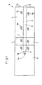
- FIG. 1 shows the essential elements of a blank A for packaging or a packaging element. From a blank of this type, in which the sections for the side wall and the top wall are omitted, a packaging can be produced which directly receives the objects and forms an inner shell, which in turn sits in an outer packaging.
- the part of the blank A shown in FIG. 1 has a wall section 1.
- This wall section is connected to further wall sections 3, 4 via fold lines 2.
- the wall sections 3, 4 form mutually opposite walls which are separated by the wall which is formed by the wall section 1 of the blank A.
- the wall section 1 can form a bottom section.
- the wall sections 3, 4 form the front or back of the packaging or the packaging element.
- Nitts A forms a side wall, the wall sections 3, 4 again forming front and rear sides. In this case, the packaging opening cannot be arranged on the top, but on the side.
- tear lines 6, 7 run through this wall section 4, cross the fold line 2 and then run into the wall section 1.
- the tear lines 6, 7 run through this wall section 1 and cross the other fold line 2 between the wall section 1 and the wall section 3.
- these tear lines 6, 7 end at a predetermined distance from the fold line 2 between the wall section 3 and the wall section 3 Wall section 1.
- These tear lines 6, 7 delimit a tear-out lifting strip 5 along its two longitudinal edges.
- a pivot point 8 is provided for the lifting strip 5, up to which the lifting strip tear lines 6, 7 extend.
- This lifting strip 5 can have a handle 9.
- the blank A shown in FIG. 1 is erected and the wall section 1 forms a bottom section
- objects can stand on this bottom section in the packaging formed by this blank A.
- These objects can be rod-shaped, such as cigarettes.
- the handle 9 can be grasped and the lifting strip 5 can be torn out of the wall sections 1, 3, 4 by a pull along the lifting strip tear lines 6, 7 and bent around the articulation point 8. Objects are lifted out of the packaging.
- adhesive sites 5h are arranged in the blank A. These adhesive spots 5h can be adhesive spots and with these adhesive spots 5h the erected blank A can then be glued in the outer pack. This makes it easy to tear out the lifting strip 5.
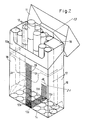
- a hard pack 10 is shown.
- the hinged lid 1 is open and the collar insert 10a is exposed.
- Some cigarettes 12 are shown in the advanced position.
- An inner wrapper that surrounds the cigarettes 12 is shown as a packaging element, namely a staniol wrapper 13, the cut of which is shown in FIG.
- a stanol cut is paper-coated and is formed from a glue-laminated aluminum foil. After the blank has been erected, the paper coating is on the inside.
- This blank has a wall section 14, which forms the bottom of the inner shell, a wall section 15, which forms a front wall, and a wall section 16, which forms a rear wall.
- the side sections 17, 18 are folded over one another and form side walls.
- the wall sections 19, 20 overlap one another in the closed state of the packaging.
- the wall section 20 is on the outside. The places of detention are omitted in FIG. 2 for the sake of clarity.
- the removable upper part 22 is shown in FIG. 3 and is delimited by a tear line 23.
- the stanol cut is partially cut along the tear line 23.
- the connection between the removable upper part 22 and the front wall section 15 consists of four web sections 24, 25, 26, 27.
- the width and number of the web sections determine, depending on the strength of the material selected, that the removable upper part 22 is torn off from the front wall section 15 required force. This is chosen so that the removable upper part 22 can be torn off without pulling out the remaining part of the staniol wrap 13.
- the stanol wrapping 13 can be fastened in the outer packaging envelope by means of adhesive points 37, 38, 39 which represent sticking points.
- the lifting strip 29 begins at 28, which is integrally formed with this removable upper part 22.
- the lifting strip 29 extends over the front wall section 15 and the wall section 14 forming the bottom into the wall section 16 which, when erected, forms the rear wall.
- This lifting strip 29 is formed in blank A by lifting strip tear lines 30, 31, which extend through the corresponding wall sections.
- these lifting strip tear lines 30, 31 are formed by cuts and web sections 32, 33, 34, 35, which lie in the front wall section 15. A continuous cut runs in the wall section 14.
- the arrangement of this tear line 36 and the width of the web sections 32 to 35 determine the respective tear forces.
- the arrangement of the tear line 36 is such that the force required to tear it off is greater than the force required to tear off the web sections 32 to 35.
- the stanol wrap 13 is fastened in the outer packaging sleeve by means of the three adhesive points 37, 38, 39.
- the removal strip 29 When the removal strip 29 is torn out, it is pivoted around the articulation point 21 in such a way that cigarettes 12 which have been picked up are pushed upwards for removal.
- the stanol wrap 13 is held securely by the adhesive points 37, 38, 39.
- the number of cigarettes 12a, 12b pushed out directly from the lifting strip 29 depend on the width of the lifting strip 29. After the first cigarettes 12 have been removed, the removal strip 29 can be torn off.
- the cigarettes 12d, 12c shown in FIG. 2 and lying next to the lifting strip 29 can also be taken along by frictional engagement.
- the tear-off strip 29 has been torn off, the packing density is loosened in such a way that the remaining cigarettes 12 can be easily removed.
- the removable upper part shown with hatching is designed as a separate cutting part 13b.
- the removable upper part shown with hatching is designed as a separate cutting part 13b.
- adhesive points 60a for connecting the blank parts 13a, 13b.
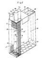
- FIG. 5 shows a stanol blank 41, the geometry of which is rotated by 90 relative to the geometry of the stanol blank shown in FIG. 3.
- the wall sections 47, 48 and 42a, 42b, 45 of this stanol blank 41 overlap.
- the wall sections 42a, 42b form the bottom.
- the wall sections 46 then form the opposite side wall.
- the removable upper part 49 is part of the front wall section 43 and the wall sections 46, 45 and also includes the wall section 48. This removable upper part 49 is delimited by tear lines 50, 51, which are cutting lines with web sections 52 to 57.
- lifting strip 58a, 58b Integral with the removable upper part 49 is the lifting strip 58a, 58b, which is delimited along its longitudinal edges by lifting strip tear lines 59, 60.
- the lifting strip tear lines 59, 60 are cutting lines with web sections 61 to 64. These lifting strip tear lines 59, 60 extend into the wall section 42.
- lifting strip tear lines 66, 67 are formed in the wall section 42b and in the wall section 44, which delimit a part 58b of the lifting strip 58a, 58b.
- the articulation point 65a for the lifting strip 58a, 58b is provided in the wall section 44, in the area of which the tear line 65b extending transversely to the longitudinal edges of the lifting strip 58a, 58b is arranged.
- the stanol lining can be fixed in an outer shell.
- FIG. 6 shows a so-called soft pack 40, from which the cigarettes 12 are removed on one side.
- the middle part of the soft pack is closed by a sealing strip, for example the control sleeve.
- the places of detention have been omitted in FIG. 6 for the sake of clarity.
- FIG. 7 shows a stanol wrap 13 ′ which is used as the inner cover in the soft pack 40 according to FIG. 6.
- This stanol wrap 13 ' has a wall section 14' which forms the bottom, a wall section 15 'which forms the front wall and a wall section 16' which forms the rear wall.
- Wall sections 17 ', 18' are provided which form the side walls.
- wall sections 19 ', 20' are provided to form the upper closure.
- the geometry of the stanol wrap 13 ' corresponds to the stanol wrap 13 shown in FIG. 2 with respect to the walls.
- a removable upper part 22 ' is provided in the corner region of the stanol wrap 13', which is delimited by a tear line 23 '.
- This tear line 23 ' is a section with a web section 26'.
- Another section with a web section 24 ' is provided in the wall section 20' to limit the removable upper part 22 '.
- This removable upper part 22 ′ is formed integrally with the lifting strip 29 ′, which is delimited along its longitudinal edges by lifting strip tear lines 30 ′, 31 ′ and extends through the wall sections 15 ′, 14 ′ and into the wall section 16 ′, in which the articulation point 21 'is provided for the lifting strip 29'.
- the tear line 36 'running transversely to the longitudinal edges of the lifting strip 29' is provided in the region of the articulation point 21 '.
- the lifting strip tear lines 30 ', 31' are formed by cuts and web sections 32 ', 33', 34, 35 'which lie in the wall section 15'.
- the lifting strip tear line 31 ' continues into a part 23'a which cuts through the edge 15'a of the wall section 15'.
- Adhesive points 37 ', 38', 38'a, 39 ' are provided.
- a further section line 40a with a web section 40b extends, as shown, through the wall section 18 'of the stanol wrap 13' and into the wall section 16 '.
- connection between the removable upper part and the lifting strip can be such that when a sufficient force is applied to the upper part, this connection is separated after the cigarettes located in its area have been pushed out by pulling out the lifting strip.
- the lifting strip then remains in the opened packaging, since its articulation point is stronger than the connection to the removable upper part.
- the lifting strip is pushed back into the packaging if the ones that have not been removed and moved cigarettes can be pushed back into the packaging.
- the hinged lid 11 of the hard pack 10 can also be connected to the adjacent end of the lifting strip. So that the lifting strip does not hinder removal of the advanced cigarettes, the upper end of the lifting strip must be fork-shaped in the region of the removable upper part. When opening the hinged cover 11, the lifting strip is pulled upwards, as already explained.
- the removable upper part must be provided with tear lines designed in such a way that when the hinged lid 11 is opened, the advanced cigarettes penetrate the removable upper part so that they are exposed.
Landscapes
- Engineering & Computer Science (AREA)
- Mechanical Engineering (AREA)
- Packaging Of Annular Or Rod-Shaped Articles, Wearing Apparel, Cassettes, Or The Like (AREA)
- Cartons (AREA)
Abstract
Claims (16)
Priority Applications (1)
| Application Number | Priority Date | Filing Date | Title |
|---|---|---|---|
| AT84902442T ATE41397T1 (de) | 1983-06-04 | 1984-06-04 | Zuschnitt fuer parallelepipedische verpackungen oder verpackungselemente. |
Applications Claiming Priority (4)
| Application Number | Priority Date | Filing Date | Title |
|---|---|---|---|
| DE19838316646 DE8316646U1 (de) | 1983-06-04 | 1983-06-04 | Packung zur Umhuellung von gleichartigen Gegenstaenden |
| DE8316646U | 1983-06-04 | ||
| DE19843410217 DE3410217A1 (de) | 1983-06-04 | 1984-03-16 | Zuschnitt fuer parallelepipedische verpackungen oder verpackungselemente |
| DE3410217 | 1984-03-16 |
Publications (2)
| Publication Number | Publication Date |
|---|---|
| EP0147447A1 EP0147447A1 (fr) | 1985-07-10 |
| EP0147447B1 true EP0147447B1 (fr) | 1989-03-15 |
Family
ID=25819532
Family Applications (1)
| Application Number | Title | Priority Date | Filing Date |
|---|---|---|---|
| EP84902442A Expired EP0147447B1 (fr) | 1983-06-04 | 1984-06-04 | Piece decoupee pour emballages parallelepipedes ou elements d'emballage |
Country Status (5)
| Country | Link |
|---|---|
| US (1) | US4664310A (fr) |
| EP (1) | EP0147447B1 (fr) |
| AU (1) | AU3060884A (fr) |
| DE (2) | DE3410217A1 (fr) |
| WO (1) | WO1984004907A1 (fr) |
Families Citing this family (19)
| Publication number | Priority date | Publication date | Assignee | Title |
|---|---|---|---|---|
| BR8604223A (pt) * | 1985-09-04 | 1987-04-28 | Focke & Co | Embalagem em forma de paralelepipedo para cigarros ou semelhantes produtos |
| US4850716A (en) * | 1987-11-20 | 1989-07-25 | Minnesota Mining And Manufacturing Company | Remotely detectable sterilization monitor |
| DE3806818A1 (de) * | 1988-03-03 | 1989-09-14 | Focke & Co | Zigaretten-packung, insbesondere klappschachtel |
| DE3806819A1 (de) * | 1988-03-03 | 1989-09-14 | Focke & Co | Zigaretten-packung, insbesondere klappschachtel |
| DE3839553A1 (de) * | 1988-11-24 | 1990-05-31 | Focke & Co | Zigaretten-packung, insbesondere klappschachtel |
| DE3904233A1 (de) * | 1989-02-13 | 1990-08-16 | Schmermund Maschf Alfred | Innenpapierzuschnitt fuer eine klappdeckelschachtel fuer zigaretten |
| AU621639B2 (en) * | 1989-03-13 | 1992-03-19 | Amcor Limited | A container |
| EP0393648A1 (fr) * | 1989-04-19 | 1990-10-24 | Karl Robert Kranemann | Emballage pour cigarettes ou analogues |
| DE9017113U1 (de) * | 1990-12-19 | 1991-04-04 | Winsel, Matthias, 4790 Paderborn | Zuglasche für Zigarettenschachteln |
| CA2093173C (fr) * | 1992-04-01 | 1999-11-02 | Pierre Radyn Swart | Bande tirette |
| ATE171133T1 (de) * | 1992-07-13 | 1998-10-15 | Stratop Management Und Treuhan | Behälter für mehrere darin befindliche gegenstände |
| WO2006025769A1 (fr) * | 2004-08-19 | 2006-03-09 | Sca Hygiene Products Ab | Systeme permettant de sortir un article absorbant d'une pile d'articles absorbants |
| DE102008047773A1 (de) | 2008-09-17 | 2010-04-15 | Focke & Co.(Gmbh & Co. Kg) | Packung für Zigaretten sowie Verfahren und Vorrichtung zum Herstellen derselben |
| US20100116874A1 (en) * | 2008-11-13 | 2010-05-13 | Gary Herbert Carmichael | Easy Opening Feature for a Taped Carton and Method Thereof |
| EP2746190A1 (fr) | 2012-12-19 | 2014-06-25 | Reemtsma Cigarettenfabriken GmbH | Dispositif pour offrir au moins une parmi plusieurs cigarettes contenues dans un paquet |
| WO2016005938A1 (fr) † | 2014-07-10 | 2016-01-14 | G.D Societa' Per Azioni | Paquet de cigarettes souple comprenant un tampon de fermeture |
| USD778150S1 (en) * | 2015-01-12 | 2017-02-07 | Maui Kahawaiolaa | Cigarette package |
| EP3313754B1 (fr) * | 2015-06-26 | 2019-08-07 | Philip Morris Products S.a.s. | Récipient pour biens de consommation muni d'une partie coulissante |
| DE102015014078A1 (de) * | 2015-11-02 | 2017-05-04 | Focke & Co. (Gmbh & Co. Kg) | Zigarettenpackung |
Family Cites Families (13)
| Publication number | Priority date | Publication date | Assignee | Title |
|---|---|---|---|---|
| GB412655A (en) * | 1933-01-19 | 1934-07-05 | George Hill | Improvements in or relating to packets or cartons for cigarettes and the like |
| DE676480C (de) * | 1935-04-09 | 1939-06-05 | Freiburger Kartonnagenfabrik E | Packung mit Aufreissvorrichtung fuer Stumpen u. dgl. |
| US2047090A (en) * | 1935-06-18 | 1936-07-07 | Walter M Woolfson | Cigar box |
| GB642831A (en) * | 1947-12-16 | 1950-09-13 | James Gagg | Improvements in or relating to cigarette packets or boxes |
| FR1030996A (fr) * | 1951-01-15 | 1953-06-18 | Nouveau procédé publicitaire et dispositifs de mise en oeuvre | |
| DE964397C (de) * | 1952-04-03 | 1957-05-23 | Guenter Wunderling Dr Med Dent | Zigarettenweichpackung mit Ausheber |
| US2801769A (en) * | 1954-09-13 | 1957-08-06 | Fund Del Inc | Cigarette pull tab ejector and the like packages |
| NL210507A (fr) * | 1955-09-16 | |||
| US3107817A (en) * | 1960-05-31 | 1963-10-22 | American Mach & Foundry | Cigarette package with a cigarette ejector |
| US3108711A (en) * | 1961-07-19 | 1963-10-29 | Evan J Anton | Cigarette package with an ejector strip for each cigarette |
| US3379364A (en) * | 1966-07-07 | 1968-04-23 | Reynolds Metals Co | Package means |
| SE362051B (fr) * | 1968-03-19 | 1973-11-26 | Akerlund & Rausing Ab | |
| DE2833389C2 (de) * | 1978-07-29 | 1983-11-10 | Focke & Co, 2810 Verden | Quaderförmige Packung für Zigaretten, Zigarillos o.dgl. |
-
1984
- 1984-03-16 DE DE19843410217 patent/DE3410217A1/de not_active Withdrawn
- 1984-06-04 DE DE8484902442T patent/DE3477181D1/de not_active Expired
- 1984-06-04 AU AU30608/84A patent/AU3060884A/en not_active Withdrawn
- 1984-06-04 WO PCT/DE1984/000126 patent/WO1984004907A1/fr active IP Right Grant
- 1984-06-04 EP EP84902442A patent/EP0147447B1/fr not_active Expired
- 1984-06-04 US US06/705,468 patent/US4664310A/en not_active Expired - Fee Related
Also Published As
| Publication number | Publication date |
|---|---|
| AU3060884A (en) | 1985-01-04 |
| DE3477181D1 (en) | 1989-04-20 |
| EP0147447A1 (fr) | 1985-07-10 |
| DE3410217A1 (de) | 1984-12-06 |
| WO1984004907A1 (fr) | 1984-12-20 |
| US4664310A (en) | 1987-05-12 |
Similar Documents
| Publication | Publication Date | Title |
|---|---|---|
| EP0147447B1 (fr) | Piece decoupee pour emballages parallelepipedes ou elements d'emballage | |
| DE69213354T2 (de) | Zigarettenpackung | |
| EP0030601B1 (fr) | Emballage souple formé à partir d'une feuille de matière plastique, en particulier pour des mouchoirs en papier | |
| DE69404102T2 (de) | Wiederverschliessbare Packung und Verfahren zur Herstellung eines Zuschnitts für eine solche Packung | |
| DE2654867C3 (de) | Verpackter Aufgußbeutel, insbe-, sondere für Tee | |
| EP0553660B1 (fr) | Emballage pour mouchoirs, flan et procédé pour sa fabrication | |
| DE1586542B2 (de) | Aufreisspackung fuer nahrungs- und genussmittel | |
| DE3329456C2 (de) | Kappenschachtel für Zigaretten oder dergleichen | |
| DE3940872C3 (de) | Faltbare Verpackung | |
| EP0218186B1 (fr) | Boîte en carton, carton ondulé ou similaire | |
| DE3624345C2 (fr) | ||
| DE9114927U1 (de) | Faltschachtel mit Klappdeckel für Zigaretten | |
| EP0816237A1 (fr) | Emballage de transport et présentation et procédé pour sa fabrication | |
| EP0399250A1 (fr) | Bande de matière d'emballage faite de flans reliés entre eux | |
| DE2135776A1 (de) | Schachtel, vorzugsweise fuer zigaretten | |
| DE4042103C2 (de) | Schuber | |
| DE2444858A1 (de) | Pappschachtel | |
| DE60121740T2 (de) | Steife verpackung für eine mehrzahl von zigarettenpackungen | |
| DE2858166C2 (de) | Quaderförmige Innenumhüllung aus dünnem Verpackungsmaterial (Stanniol-Folie o.dgl.) für Zigaretten o.dgl. | |
| DE69614120T2 (de) | Verfahren zum Verpacken eines Stapels von blattförmigen Gegenständen | |
| DE9419553U1 (de) | Packung für gestapelte Kleinbogen | |
| DE2848129A1 (de) | Verfahren zur herstellung einer packung sowie packung | |
| EP0158597A2 (fr) | Flan à dispositif verseur refermable | |
| EP0575689B1 (fr) | Carton d'emballage pour piles de papier | |
| DE1586542C3 (de) | Aufreißpackung für Nahrungs- und Genußmittel |
Legal Events
| Date | Code | Title | Description |
|---|---|---|---|
| PUAI | Public reference made under article 153(3) epc to a published international application that has entered the european phase |
Free format text: ORIGINAL CODE: 0009012 |
|
| AK | Designated contracting states |
Designated state(s): AT BE CH DE FR GB LI LU NL SE |
|
| 17P | Request for examination filed |
Effective date: 19850613 |
|
| 17Q | First examination report despatched |
Effective date: 19870318 |
|
| GRAA | (expected) grant |
Free format text: ORIGINAL CODE: 0009210 |
|
| AK | Designated contracting states |
Kind code of ref document: B1 Designated state(s): AT BE CH DE FR GB LI LU NL SE |
|
| PG25 | Lapsed in a contracting state [announced via postgrant information from national office to epo] |
Ref country code: SE Effective date: 19890315 Ref country code: NL Effective date: 19890315 Ref country code: GB Free format text: LAPSE BECAUSE OF NON-PAYMENT OF DUE FEES Effective date: 19890315 Ref country code: FR Free format text: THE PATENT HAS BEEN ANNULLED BY A DECISION OF A NATIONAL AUTHORITY Effective date: 19890315 Ref country code: BE Effective date: 19890315 |
|
| REF | Corresponds to: |
Ref document number: 41397 Country of ref document: AT Date of ref document: 19890415 Kind code of ref document: T |
|
| REF | Corresponds to: |
Ref document number: 3477181 Country of ref document: DE Date of ref document: 19890420 |
|
| PG25 | Lapsed in a contracting state [announced via postgrant information from national office to epo] |
Ref country code: AT Effective date: 19890604 |
|
| PG25 | Lapsed in a contracting state [announced via postgrant information from national office to epo] |
Ref country code: LU Free format text: LAPSE BECAUSE OF NON-PAYMENT OF DUE FEES Effective date: 19890630 Ref country code: LI Effective date: 19890630 Ref country code: CH Effective date: 19890630 |
|
| EN | Fr: translation not filed | ||
| NLV1 | Nl: lapsed or annulled due to failure to fulfill the requirements of art. 29p and 29m of the patents act | ||
| GBV | Gb: ep patent (uk) treated as always having been void in accordance with gb section 77(7)/1977 [no translation filed] | ||
| PLBE | No opposition filed within time limit |
Free format text: ORIGINAL CODE: 0009261 |
|
| STAA | Information on the status of an ep patent application or granted ep patent |
Free format text: STATUS: NO OPPOSITION FILED WITHIN TIME LIMIT |
|
| REG | Reference to a national code |
Ref country code: CH Ref legal event code: PL |
|
| 26N | No opposition filed | ||
| PGFP | Annual fee paid to national office [announced via postgrant information from national office to epo] |
Ref country code: DE Payment date: 19931221 Year of fee payment: 10 |
|
| PG25 | Lapsed in a contracting state [announced via postgrant information from national office to epo] |
Ref country code: DE Effective date: 19950301 |