EP0147366B1 - Dispositif de développement de matériel photographique exposé - Google Patents
Dispositif de développement de matériel photographique exposé Download PDFInfo
- Publication number
- EP0147366B1 EP0147366B1 EP84810560A EP84810560A EP0147366B1 EP 0147366 B1 EP0147366 B1 EP 0147366B1 EP 84810560 A EP84810560 A EP 84810560A EP 84810560 A EP84810560 A EP 84810560A EP 0147366 B1 EP0147366 B1 EP 0147366B1
- Authority
- EP
- European Patent Office
- Prior art keywords
- cassette
- film
- space
- spool
- liquid
- Prior art date
- Legal status (The legal status is an assumption and is not a legal conclusion. Google has not performed a legal analysis and makes no representation as to the accuracy of the status listed.)
- Expired
Links
- 239000000463 material Substances 0.000 title description 2
- 239000007788 liquid Substances 0.000 claims description 53
- 238000009423 ventilation Methods 0.000 claims description 2
- 230000001419 dependent effect Effects 0.000 claims 4
- 230000008602 contraction Effects 0.000 claims 1
- 230000008878 coupling Effects 0.000 description 5
- 238000010168 coupling process Methods 0.000 description 5
- 238000005859 coupling reaction Methods 0.000 description 5
- 238000004804 winding Methods 0.000 description 5
- 238000000034 method Methods 0.000 description 4
- XLYOFNOQVPJJNP-UHFFFAOYSA-N water Substances O XLYOFNOQVPJJNP-UHFFFAOYSA-N 0.000 description 4
- 238000013019 agitation Methods 0.000 description 3
- 238000010276 construction Methods 0.000 description 2
- 230000000694 effects Effects 0.000 description 2
- 238000003672 processing method Methods 0.000 description 2
- 238000010521 absorption reaction Methods 0.000 description 1
- 230000001680 brushing effect Effects 0.000 description 1
- 239000000834 fixative Substances 0.000 description 1
- 239000012530 fluid Substances 0.000 description 1
- 230000013011 mating Effects 0.000 description 1
- 239000002184 metal Substances 0.000 description 1
- 238000012986 modification Methods 0.000 description 1
- 230000004048 modification Effects 0.000 description 1
- 230000000149 penetrating effect Effects 0.000 description 1
- 230000000284 resting effect Effects 0.000 description 1
- 238000006748 scratching Methods 0.000 description 1
- 230000002393 scratching effect Effects 0.000 description 1
- 238000005406 washing Methods 0.000 description 1
Images


Classifications
-
- G—PHYSICS
- G03—PHOTOGRAPHY; CINEMATOGRAPHY; ANALOGOUS TECHNIQUES USING WAVES OTHER THAN OPTICAL WAVES; ELECTROGRAPHY; HOLOGRAPHY
- G03D—APPARATUS FOR PROCESSING EXPOSED PHOTOGRAPHIC MATERIALS; ACCESSORIES THEREFOR
- G03D13/00—Processing apparatus or accessories therefor, not covered by groups G11B3/00 - G11B11/00
- G03D13/02—Containers; Holding-devices
- G03D13/04—Trays; Dishes; Tanks ; Drums
- G03D13/06—Light-tight tanks with provision for loading in daylight
Definitions
- the invention relates to an apparatus for processing exposed photographic film material.
- US-A-2 781 708 a film is loaded into a very special type of film holder or cartridge, and the cartridge requires the use of a special camera, since it does not correspond to the well-known film cassette, as is most common for 35 mm film is used.
- US-A-3 605 601 and US-A-4 001 857 describe devices in which the film is processed on a spool in place in a film cassette. In practice, it has been shown that films treated in such devices are processed very unevenly and therefore give unsatisfactory results.
- US-A-4 134 666 describes a film processing method in which the film is transferred from the cassette to a spool which can be placed in a light-tight envelope.
- the object of the invention is therefore primarily to provide a device of the type described above, which is simpler in construction and easier to use than the known devices described above.
- This apparatus according to the invention can serve to empty the contents of cassettes in daylight into a processing space which takes up little space and which, although no spiral member is used to hold the film, can nevertheless give good processing results.
- Preferred embodiments of the device according to the invention have one or more of the special features described in the subclaims.
- the treatment room under the cassette holding block in the housing of the device according to the invention can not only be supplied with liquid through the channels or passages in the cover or bottom of the device mentioned in the subclaims, but also through the side wall of the housing
- Treatment room leading tube can be provided through which the treatment liquid is introduced into the treatment room and emptied when the device is reversed.
- the treatment space below the cartridge body must of course contain enough liquid to process the film therein completely and uniformly, but the amount of liquid required is usually much less than that required in most spiral processing drums.
- the liquid must be poured into the treatment room before the cassette is inserted into the device.
- the film winding becomes increasingly loose, its radial diameter increases, and the treatment liquid can penetrate between the film coils and act on the entire surface of the film.
- one hub end of the spool carrying the wound film protrudes noticeably from one end cap of the cassette, in contrast to the other end.
- This longer hub end is preferably blasted off and a lock is provided on the device which prevents the cassette from being tampered with, e.g. H. the shorter hub end can be inserted into the holding block.
- the same can also be achieved in that a light-tight placement of the cover on the housing of the device is only possible if not the longer, but the shorter hub end is facing the cassette inserted into the holding block at the top, i.e. the cover. When the longer end of the hub is at the top, the cover cannot be screwed onto or over the housing.
- a compressive attack of the holding block on the cassette body can be achieved in addition to using a longitudinally split cylinder as a holding block in that the holding block consists of two cylinder halves which are held together more or less by screw connections. In this way, a maximum holding of the cassette is achieved, which is particularly important with firmly attached end caps.
- the ejection member e.g. B. an ejection piston or - thorn, which holds the spool with the film at its lower end, pushed or screwed through the cassette so far that the lower end of the spool is at the bottom of the liquid treatment room in the housing of the device.
- the ejection member can then be rotated in both directions, i.e. to the left or to the right.
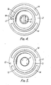
- a conventional 35 mm film cassette A which comprises two annular end caps B1 and B2 and a substantially cylindrical cassette body C, which is formed by clamping the two ends of a suitable metal strip and with a light-tight, axially to the body longitudinal axis extending film exit slot between two out of the wall of the cassette body C or tangentially projecting lips D is provided.
- the cassette body C is intended to hold a film wound on a flange spool E provided with a long hub end F and a short hub end G.
- a crossbar H extends diametrically across the hub from the hub end G and allows the film to be unwound onto or from the reel in a camera past the exposure chamber.
- the film J has a leading edge K and usual transport holes L.
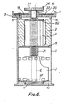
- FIGS. 2 to 6 show a processing device which comprises three main parts, namely a columnar, in particular a cylindrical housing 1, a cassette holding block 2 and a light-tight cover 3, to which a piston-like coil ejection member 4 is connected.
- the cassette is also shown and labeled A.
- the housing 1 and the cover 3 are made of opaque plastic.
- the housing 1 has an open upper end 6 provided with two diametrically opposed bayonet locking slots 19; the slots 19 are intended for receiving two pins 7 on the cover 3.
- the cover 3 is fastened to the housing 1 by this bayonet lock.
- the housing 1 comprises an inner ring flange, on which an upwardly directed pin 8 is formed, which serves to secure the cassette holding block Z in its position on the ring flange against rotation in the housing 1. Below the inner ring flange there is a chamber 9 in the housing 1 which is intended to receive treatment liquid.
- the lower end of the housing 1 is closed by a removable base plate 10, on the inside of which a recess 11 is provided, into which the end cap B1 of the cassette falls during operation.
- the holding block 2 for the cassette body C is a cylindrical body of annular cross section with a centrally arranged cylindrical passage space (bore) 12, into which the loaded cassette fits.
- a recess 15 (FIGS. 4 and 5) is provided, into which the pin 8 of the housing 1 fits and thus fixes the position of the holding block 2 in the housing 1.
- An axially extending groove 13 opens at the top and into the cylindrical passage space 12 and, when the loaded cassette is fitted into the passage space 12, serves to accommodate the lips which protrude radially outward on both sides of the film exit slot D, the film cassette A, but the groove 13 is closed at the lower end.
- the holding block 2 is further formed with two passages or passages 14 of arcuate cross-section for liquid, which are arranged diametrically opposite one another on both sides of the passage space 12 and extend through the block 2 in the axial direction.
- the lid 3 has a cup-shaped upper end 17 and is provided in the lid surface with openings 18 which are covered by a light-tight disc 20.
- the disk 20 is fastened to the lid by means of screws in such a way that it is held a short distance above the lid surface and forms the upper wall of an inflow path for liquids on the periphery of the disk 20 to the lid openings 18.
- an ejection piston 4 provided with an external thread 21, which can be screwed downwards and upwards through a central opening 22 of the cover 3 provided with an internal thread. 3, the upper end position of the discharge piston 4 is shown. At its lower end, the piston 4 is provided with a transverse slot 23 which fits on the transverse web H of the upper hub end G of the coil E. The upper end of the coil ejection piston 4 carries a wheel 24 with a rotary handle 25.
- FIGS. 4 and 5 show how a cassette A fits into the passage space 12 of the block 2, the lips D of the film exit slot of the cassette protruding into the groove 13 of the block 2 which is closed at its lower end.
- the holder block 2 for the cassette body is inserted into the upper open end 6 of the housing 1.
- An exposed piece of film J is wound in the cassette A so that it is completely inside the cassette, and the cassette A is now inserted into the cylindrical passage space 12 from its upper open end so that the lips of the film exit slot, D, in the open groove 13 protrude into the wall of the passage space 12, whereby the cassette A is prevented from rotating in the holding block 2.
- the cassette A is inserted so that the longer hub end F of the reel E points downward.
- the cover 3 is then fitted onto the housing, the transverse slot 23 being placed in the lower end of the ejection piston 4 on the crosspiece H of the coil E and the screw connection of the piston 4 with the cover 3 being adjusted such that an annular flange 16 on the underside of the cover 3 protrudes downwards, fits into the open upper end 6 of the housing.
- the bayonet lock then serves to connect the cover 3 to the housing 1 in a light-tight manner by engagement of the pins 7 on the cover 3 in the slots 19 of the upper housing end 6.
- the processing device is then held on a flat surface and the wheel 24 is rotated by hand with the aid of the handle 25, so that the pushing piston 4 is screwed downward into the housing 1, whereby it moves downward onto the spool E and thus onto the cassette end flap B1 exerts directed pressure.
- the length of the screw stroke of the ejection piston 4 is dimensioned such that the piston stops when the hub end protruding downward F of the coil E is located in the end cap B1 in the recess 11.
- the cassette body C with the upper end cap B2 still remains in its position in the passage space 12 of the holding block 2. Because the cassette body C is not pushed by the ejection piston 4 through the holding block 2, because thanks to the fact that the groove 13 is closed at the end, the lips of the film exit slot D, which are firmly connected to the cassette body C, in the groove 13 are held and thus prevent the cassette body C from passing through the holding block 2.
- the entire process of loading the cassette A into the processing device and actuating the ejection piston 4 in order to press the reel with the film on it into the chamber 9 can be carried out in full daylight, since the film itself is protected against the light , because it is either in the cassette or in the light-tight envelope, which is formed by the columnar housing 1 and the base plate 10 'and the lid 3, both of which are light-tight.
- Processing of the exposed film can now begin.
- a measured amount of processing liquid is poured into the cup-shaped upper end 17 of the cover 3 and flows below the light-closing disc 20 to the openings 18 and through the passages 14 in the holding block 2 into the chamber 9 in the housing 1.
- the wheel 24 is then rotated back and forth to cause agitation of the liquid by means of the film and to achieve an even effect on the film over its entire length.
- the device After a reasonable time, the device is turned upside down and the used processing liquid flows out of it again through the openings 18. The device can then be charged with another processing liquid for further processing of the film or with water for washing the film.
- a monobath solution containing both a developer and a fixative can be used.
- the device is inverted and the bottom plate 10 is removed, whereupon the film inside the device can be washed with water.
- a developer solution and then a fixing solution can be used, after which the film is then washed in the device with water.
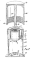
- FIG. 7 shows a further embodiment of the device according to the invention, which has a column-like housing 30, a cassette holding block 31 and a cover 32 with an ejection piston 33 mounted on the inside.
- the housing 30 has at its upper open end on its wall an external thread 34 and has an inner ring flange or shoulder 35 on its inner wall, on which the holding block 31 can rest.
- Beneath the ring flange 35 is located in the housing 30 the chamber 37 for receiving the treatment liquid, the lower end of which is closed by a removable base plate 36.
- the latter has a recess 38 in its wall surface facing the interior of the chamber for receiving a falling end cap of the cassette.
- the holding block 31 is designed similar to that shown in Figures 1 to 6 and comprises a hollow interior into which the cassette body C fits and an axial groove open at the top and inside of the block, into which the from the side wall of the cassette A on both sides of the film exit slot fit excellent lips D.
- the cover 32 comprises a closed end 39, on the inside of which the axially downwardly extending ejection mandrel 33 attaches.
- This ejection mandrel 33 has at its lower end a transverse slot 40 which fits on the transverse web H of the spool E in the cassette A.
- the cover has a lower open end 42 with an internal thread 43 that corresponds to the external thread 34 of the tubular housing 30.
- the housing 30 and the cover 32 are both made of opaque plastic.
- the transverse slot 40 at the lower end of the ejection mandrel 33 is now brought into engagement with the transverse web H of the coil E and the cover 32 is then screwed down onto the housing 30 with the aid of the threads 34, 43.
- the end cap 31 is pushed away from the lower end of the cassette body C and falls into the recess 38. Further screwing down of the cover 32 on the housing 30 now causes the internal thread 43 to get under the external thread 34 and detaches itself from this. This now makes it possible to push the cover 31 downwards so far that the ejection mandrel 33 presses the spool E with the film J wound onto it into the liquid in the space 37 of the housing 31.
- This downward movement of the ejection mandrel 33 is performed quickly to ensure that all areas of the film are as possible be immersed in the liquid at the same time. This is especially important if a monobath is used. Movement of the liquid in contact with the film can be achieved by shaking the device or by repeatedly placing it upside down and re-erecting it at certain time intervals.
- the device according to FIG. 7 is of particularly simple construction and is cheaper and easier to handle than the device according to FIGS. 2 to 6, but it is only suitable for treatment with a monobath. On the other hand, with the device according to FIGS. 2 to 6, it is particularly easy to achieve uniform development and complete fixation.
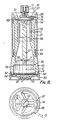
- Fig. 8 shows a further embodiment of the processing device according to the invention, in which it comprises a column-shaped housing 50, on which a hollow cylindrical cover part 51 is placed, which has an internal thread 53 on the inner wall of its lower open end, which has the external thread 52 corresponds to the outer wall at the upper open end of the housing 50.
- the same internal thread 53 also fits an external thread 54 provided further down on the outer wall of the housing, with which it can be screwed after it has been screwed downwards over the external thread 52.
- a cassette holding block 55 is inserted resting in the upper part of the housing 50 on appropriately designed shoulders in the inner edges of radially inwardly projecting ribs 56.
- An ejection mandrel 57 is attached to the cover 51 and has an elastically flexible forked lower end 58 which can be firmly seated on the crossbar H of the coil E, so that the coil is also held at the lower end of the ejection mandrel 57 after it has been removed from the Cartridge body C held in the holding block 55 has been pushed out downward.
- the ribs 56 advantageously have outwardly tapered inner edges in their lower portions, thereby allowing the film J on the spool E to unwind somewhat while the spool is being ejected from the cassette body C.
- the liquid-receiving chamber 59 is located in the housing 50.
- a downward-pointing annular shoulder 60 is provided in the upper region of the chamber 59, which projects into this part of the chamber 59 and contributes to this Spread out the leading edge K of the film J, or to facilitate the spreading of the film roll in the lower region of the chamber 59.
- two pointed pins 62 protrude radially into the chamber interior and penetrate into the transport holes L only in the outermost winding of the film J, which is assisted by the spreading of the windings of the leading edge K of the film.
- the chamber 59 is closed at its lower end by the removable base plate 63, which is sealed by an O-ring 64.
- the base plate 63 is provided with steps 65 towards its center and there receives the downwardly repelled end cap B1, through the central opening of which the hub end F of the coil E protrudes and thus ensures that the falling cap B1 securely into the center of the base plate 63 comes to rest, as shown in Fig. 8.
- the cover part 51 has three recesses 68 in its upper end face 67, each of which, as can be seen in FIG. 9, has an opening 69 at its bottom end which is connected to the interior of the housing 50.
- a slight deflection is caused by an annular flange 70 which is fixed on the ejection mandrel 57 and prevents light from penetrating into the housing 69 through the holes 69.
- liquid can be poured into the recesses 68 and flow through the openings 69 into the housing 50 and past the cassette holding block 55 into the chamber 59, but thanks to the ring flange 70 no light can fall into the interior of the housing.
- a mandrel rotary knob 72 is provided, which is connected to the mandrel by means of a coupling 73.
- a resilient stop member 74 On the underside of the lid rim 67 there is a resilient stop member 74, which usually points obliquely downwards with its free end away from the center of the lid, so that it projects into the rotational path of a pin 75 protruding upward from the ring flange 70, as shown in FIG. 9 can be seen, as a result of which the cover and the ejection mandrel 57 can be coupled to one another during rotation.
- Figure 10 is a top view of the cassette support block 55 and shows that it is indeed a split cylinder.
- four axial grooves 77 are uniformly provided around the block, into which the ribs 56 fit with their upper inner edges.
- the longitudinal groove 79 shows the required groove cross section which is suitable for receiving the slot lips of a cassette of the type shown in FIG. 1 with an angled film exit slot
- the longitudinal groove 80 has a cross-sectional shape which is suitable for cassettes with a tangentially directed exit slot.
- Both types of longitudinal grooves, 79 and 80 are present in the holding block 55, so that the device according to the invention can be used both for cassettes with angled film exit and for those with tangential film exit.
- the end of the exposed film is completely wound into the cassette and the cassette is then inserted into the holding block 55 using the appropriate groove.
- the holding block 55 is then pressed into the housing 50 of the device so that the ribs 56 fit into the axial grooves 77 of the split cylinder constituting the block 55 and compress the block somewhat. (With the arrangement of the longitudinal grooves 79 and 80 as shown in Fig. 10, it is impossible to insert the cassette upside down into the block 55 with the boss end F protruding upward.)
- the forked end 58 of the ejection mandrel 57 is then pressed onto the crossbar H of the coil E with a tight fit.
- the cup-shaped cover part 51 is then screwed onto the housing 50 by means of the mutually matching threads 52 and 53. Initially, the mandrel 57 and the cover part 51 can only be rotated together with one another, since the stop member 74 abuts the stop pin 75. However, to the extent that the cover 51 is screwed further down over the housing 50, the stop member 74 comes into contact with the upper edge of the housing 50 and, when the cover part 51 is screwed down further, releases the rotation path of the stop pin 75.
- the stop member 74 lies in a recess 81 in the underside of the top cover part.
- the ejection mandrel 57 can be rotated further downwards by means of the rotary knob 72 and under the control of the coupling device 73.
- the ejection mandrel 57 now presses on the reel E in the cassette and first blows off the lower end cap B1 thereof.
- the mating threads 52 and 53 permit further screwing down until the spool E with the film wound thereon leaves the cassette body C.
- the cover part 51 slides down over the outer wall of the housing 50 until its internal thread 53 engages with the lower external thread 54 on the housing 50 and thus secures the cover part 51 on the housing 50 against wobbling.
- the ejection mandrel 57 When the threads 53 and 54 come into engagement with each other, the ejection mandrel 57 is fully screwed down and carries at its lower, forked end 58 the spool E with the wound film J, the lower leading edge K of which has started to spread.
- the pin 75 has been released by the stop member 74, which has remained raised since its support on the upper end of the housing 50. This allows it to take effect. of the coupling device 73 and the rotation of the ejection mandrel 57 and the film attached to it in the left or right direction by means of the rotary knob 72.
- the ejection mandrel 57 is then rotated until the pointed pins 62 enter the transport holes L.
- the coupling device 73 has an overhaul function, so that once the film edge K is in engagement with the pins 62, further unwinding of the film from the spool E is prevented and the film is also prevented from being too largely wound up in the opposite sense.
- the coupling device thus permits limited winding and unwinding of the film onto and from the spool during the subsequent treatment with the liquid in the chamber 59 containing the same in the housing 50.
- a required amount of treatment liquid is introduced into the chamber 59 through the openings 69 in the lid sufficient to cover all of the film on the spool.
- the ejection mandrel 57 is immediately rotated first in one direction and then in the other, the film alternating somewhat from the spool: and being wound onto it again.
- This movement of the film in the liquid circulates it in the chamber 59 and causes a satisfactory agitation of the liquid in contact with the film surface. This ensures an even treatment of the film.
- the device is turned upside down and the liquid is emptied therefrom through the openings 69.
- Another treatment liquid can then be added to the device through openings 69 and the ejection mandrel moved again as previously described to achieve a uniform treatment. Finally, water can be added to the device if necessary.
- the base plate 63 of the device is removed from the housing 50 and the finished film reel can be removed from the device.
- FIGS. 11 and 12 Further modifications of the lower area of the processing device in the embodiment according to FIG. 8 are shown in FIGS. 11 and 12.
- the modified device corresponds in all parts except for the modified, removable bottom plate of the liquid receiving chamber 9 in the housing 50 to the device shown in FIG. 8.
- the base plate 82 comprises a complex labyrinth system of openings and deflecting walls 83. These are arranged in such a way that when the device according to FIG. 11 is placed in a treatment bath, liquid can flow from the bath into the chamber 59 up to the level of the bath. If the device is lifted out of the bath after the end of the treatment, all of the liquid present in the chamber 59 flows out of the device again along the flow paths indicated by arrows in FIG. 11.
- the cassette is inserted into the same manner
- the device is inserted and the film on the reel E is ejected from the cassette in the same manner as described with respect to the device in the embodiment according to FIGS. 8 to 10.
- the device instead of pouring liquid through the openings 69 into the chamber 59, the device is then placed in a bath of the desired treatment liquid, the liquid level of which is sufficiently high in the liquid container to completely immerse the film on the spool. The liquid then penetrates into the chamber 59 up to this level, while the flange 70 together with the openings 69 allow light-tight ventilation.
- the ejection mandrel 57 is then rotated first in one direction and then in the other, as was also described in the device according to FIGS. 8 to 10.
- the device is lifted out of the treatment bath and the liquid is completely emptied out of the chamber 59 containing the same through the openings 83.
- the removable base plate 90 has a stepped central region 91 which is intended to receive the detached cassette cap and leads to a wide passage 92 which opens downwards into a cavity 93 in the lower region of the base plate 90 . If an end cap B1 falls into the area 91, it can slide into the wide passage 92 and through this into the cavity 93 by tilting the device. Subsequent tilting of the device in the opposite direction then causes end cap B1 to slide on the bottom of cavity 93 to a bottom opening 94 through which end cap B1 falls outside of the device. The device can then be placed in a bath of processing fluid, which then enters the device through the bottom opening 94. The bottom opening 94 is shielded from the incidence of light by the underside of the stepped region 91 of the bottom plate 90. After treatment is complete, the device is lifted out of the bath and the liquid flows out of the device through the bottom opening 94 again.
- an automatic pivoting or rotating device can be connected to the rotary knob 72 of the ejection mandrel 57 in the device according to FIGS. 8 to 12, whereby an effective agitation of the film in the liquid chamber 59 can be generated in a convenient manner.
Landscapes
- Physics & Mathematics (AREA)
- General Physics & Mathematics (AREA)
- Photographic Developing Apparatuses (AREA)
- Photographic Processing Devices Using Wet Methods (AREA)
Claims (20)
Priority Applications (1)
| Application Number | Priority Date | Filing Date | Title |
|---|---|---|---|
| AT84810560T ATE34046T1 (de) | 1983-11-23 | 1984-11-19 | Verarbeitungsgeraet fuer belichtetes photographisches filmmaterial. |
Applications Claiming Priority (4)
| Application Number | Priority Date | Filing Date | Title |
|---|---|---|---|
| GB8331265 | 1983-11-23 | ||
| GB838331265A GB8331265D0 (en) | 1983-11-23 | 1983-11-23 | Developing drum |
| GB848427101A GB8427101D0 (en) | 1984-10-26 | 1984-10-26 | Processing device |
| GB8427101 | 1984-10-26 |
Publications (2)
| Publication Number | Publication Date |
|---|---|
| EP0147366A1 EP0147366A1 (fr) | 1985-07-03 |
| EP0147366B1 true EP0147366B1 (fr) | 1988-05-04 |
Family
ID=26287030
Family Applications (1)
| Application Number | Title | Priority Date | Filing Date |
|---|---|---|---|
| EP84810560A Expired EP0147366B1 (fr) | 1983-11-23 | 1984-11-19 | Dispositif de développement de matériel photographique exposé |
Country Status (6)
| Country | Link |
|---|---|
| US (1) | US4586803A (fr) |
| EP (1) | EP0147366B1 (fr) |
| AU (1) | AU570085B2 (fr) |
| CA (1) | CA1237934A (fr) |
| DE (1) | DE3470964D1 (fr) |
| DK (1) | DK159179C (fr) |
Families Citing this family (9)
| Publication number | Priority date | Publication date | Assignee | Title |
|---|---|---|---|---|
| GB8427101D0 (en) * | 1984-10-26 | 1984-12-05 | Ciba Geigy Ag | Processing device |
| DE3437046C2 (de) * | 1984-10-09 | 1987-03-19 | Agfa-Gevaert Ag, 5090 Leverkusen | Vorrichtung zur Entnahme des Films aus einer Filmpatrone |
| US4678309A (en) * | 1985-03-07 | 1987-07-07 | Ciba-Geigy Ag | Device for processing a role of exposed film coiled on a spool |
| GB8505843D0 (en) * | 1985-03-07 | 1985-04-11 | Ciba Geigy Ag | Processing device |
| GB8516055D0 (en) * | 1985-06-25 | 1985-07-31 | Ciba Geigy Ag | Processing device |
| GB8516057D0 (en) * | 1985-06-25 | 1985-07-31 | Ciba Geigy Ag | Turning device |
| GB8707133D0 (en) * | 1987-03-25 | 1987-04-29 | Ciba Geigy Ag | Processing device |
| DE29519170U1 (de) * | 1995-12-04 | 1996-01-25 | Basf Magnetics Gmbh, 68165 Mannheim | Trennvorrichtung für einen Gegenstand |
| CN101683790B (zh) * | 2002-12-24 | 2013-01-02 | 迪默公司 | 打印装置和盒 |
Family Cites Families (8)
| Publication number | Priority date | Publication date | Assignee | Title |
|---|---|---|---|---|
| DE641854C (de) * | 1933-04-01 | 1937-02-15 | Gust Rafflenbeul Fa | Rollfilmspule |
| US2781708A (en) * | 1953-12-04 | 1957-02-19 | Parker Pen Co | Self-contained developing unit |
| US3605601A (en) * | 1968-02-27 | 1971-09-20 | Shigeru Okayama | Automatic film developing apparatus |
| JPS50105457U (fr) * | 1974-02-04 | 1975-08-29 | ||
| SE398559B (sv) * | 1976-10-05 | 1977-12-27 | Lindgren Bertil | Filmkassettoppnare |
| JPS5356025A (en) * | 1976-11-01 | 1978-05-22 | Medeika Kk | Device for developing photographic film |
| DE2743791C2 (de) * | 1977-09-29 | 1985-04-25 | JOBO Labortechnik GmbH u. Co KG, 5270 Gummersbach | Verschlußkappe für Deckel an Tanks, Trommeln o.dgl. zur Entwicklung von fotografischem Material |
| EP0078773B1 (fr) * | 1981-11-04 | 1985-02-06 | Ciba-Geigy Ag | Appareil combiné d'extraction de film de la cassette et de développement |
-
1984
- 1984-11-19 EP EP84810560A patent/EP0147366B1/fr not_active Expired
- 1984-11-19 DE DE8484810560T patent/DE3470964D1/de not_active Expired
- 1984-11-20 US US06/673,275 patent/US4586803A/en not_active Expired - Fee Related
- 1984-11-21 CA CA000468298A patent/CA1237934A/fr not_active Expired
- 1984-11-22 AU AU35803/84A patent/AU570085B2/en not_active Ceased
- 1984-11-22 DK DK554984A patent/DK159179C/da active
Also Published As
| Publication number | Publication date |
|---|---|
| EP0147366A1 (fr) | 1985-07-03 |
| DK159179B (da) | 1990-09-10 |
| DK554984D0 (da) | 1984-11-22 |
| AU3580384A (en) | 1985-05-30 |
| DK159179C (da) | 1991-02-11 |
| AU570085B2 (en) | 1988-03-03 |
| CA1237934A (fr) | 1988-06-14 |
| DE3470964D1 (en) | 1988-06-09 |
| DK554984A (da) | 1985-05-24 |
| US4586803A (en) | 1986-05-06 |
Similar Documents
| Publication | Publication Date | Title |
|---|---|---|
| DE3740572C2 (de) | Einwegkamera | |
| DE3735488A1 (de) | Mit einem objektiv bestueckte fotografische filmpackung | |
| EP0147366B1 (fr) | Dispositif de développement de matériel photographique exposé | |
| DE69425547T2 (de) | Filmkassettenmagazin | |
| EP0078773B1 (fr) | Appareil combiné d'extraction de film de la cassette et de développement | |
| DE1522914B1 (de) | Lichtdichtumschlossenes Rollfilmmagazin | |
| DE2748778A1 (de) | Vorrichtung zur entwicklung eines belichteten films | |
| EP0207896B1 (fr) | Appareil de traitement de film | |
| DE2458276C2 (de) | Vorrichtung zum Entwickeln von fotografischem Entwicklungsgut | |
| EP0194971B1 (fr) | Appareil de traitement de matériel photographique exposé | |
| DE7232103U (de) | Vorrichtung zum entwickeln eines fotografischen aufzeichnungsmaterials | |
| EP0180545B1 (fr) | Appareillage pour le développement d'un film exposé enroulé sur une bobine | |
| DE69416730T2 (de) | Führungskarte zur Befestigung an photographischem Filmstreifen mit zwei an einem Ende befindlichen Löchern | |
| EP0197002A1 (fr) | Appareil de traitement | |
| EP0207897B1 (fr) | Dispositif de manipulation d'un piston dans un dispositif de développement, spécialement des films imprimés | |
| DE491543C (de) | Tageslichtentwicklungsvorrichtung fuer Rollfilme | |
| EP0078772B1 (fr) | Appareil de traitement pour matériel photographique exposé | |
| DE3703578A1 (de) | Vorrichtung zur behandlung von lichtempfindlichem material | |
| DE526839C (de) | Vorrichtung zum Entwickeln belichteter photographischer Streifen | |
| EP0007540B1 (fr) | Boîte pour cassette de bande d'enregistrement magnétique | |
| DE835992C (de) | Einrichtung zur Entwicklung von Kleinstbildern | |
| DE510169C (de) | Entwicklungsvorrichtung fuer photographische Zwecke | |
| DE3029139A1 (de) | Trageinrichtung fuer ein blatt photographischen papieres | |
| DE3225383A1 (de) | Geraet zum entwickeln und nachbehandeln von ringscheibenfoermigem, von einer zentralen tragscheibe gehaltenem fotografischem entwicklungsgut | |
| EP0286588A1 (fr) | Dispositif pour le traitement de film photographique illuminé, enroulé sur un noyau |
Legal Events
| Date | Code | Title | Description |
|---|---|---|---|
| PUAI | Public reference made under article 153(3) epc to a published international application that has entered the european phase |
Free format text: ORIGINAL CODE: 0009012 |
|
| 17P | Request for examination filed |
Effective date: 19841122 |
|
| AK | Designated contracting states |
Designated state(s): AT BE CH DE FR GB IT LI SE |
|
| 17Q | First examination report despatched |
Effective date: 19861113 |
|
| GRAA | (expected) grant |
Free format text: ORIGINAL CODE: 0009210 |
|
| AK | Designated contracting states |
Kind code of ref document: B1 Designated state(s): AT BE CH DE FR GB IT LI SE |
|
| REF | Corresponds to: |
Ref document number: 34046 Country of ref document: AT Date of ref document: 19880515 Kind code of ref document: T |
|
| GBT | Gb: translation of ep patent filed (gb section 77(6)(a)/1977) | ||
| ITF | It: translation for a ep patent filed | ||
| REF | Corresponds to: |
Ref document number: 3470964 Country of ref document: DE Date of ref document: 19880609 |
|
| ET | Fr: translation filed | ||
| PLBE | No opposition filed within time limit |
Free format text: ORIGINAL CODE: 0009261 |
|
| STAA | Information on the status of an ep patent application or granted ep patent |
Free format text: STATUS: NO OPPOSITION FILED WITHIN TIME LIMIT |
|
| 26N | No opposition filed | ||
| REG | Reference to a national code |
Ref country code: CH Ref legal event code: PUE Owner name: ILFORD LIMITED |
|
| REG | Reference to a national code |
Ref country code: GB Ref legal event code: 732 |
|
| REG | Reference to a national code |
Ref country code: FR Ref legal event code: TP |
|
| ITPR | It: changes in ownership of a european patent |
Owner name: CESSIONE;ILFORD LIMITED |
|
| PGFP | Annual fee paid to national office [announced via postgrant information from national office to epo] |
Ref country code: AT Payment date: 19911009 Year of fee payment: 8 |
|
| PGFP | Annual fee paid to national office [announced via postgrant information from national office to epo] |
Ref country code: SE Payment date: 19911014 Year of fee payment: 8 |
|
| PGFP | Annual fee paid to national office [announced via postgrant information from national office to epo] |
Ref country code: CH Payment date: 19911015 Year of fee payment: 8 |
|
| PGFP | Annual fee paid to national office [announced via postgrant information from national office to epo] |
Ref country code: BE Payment date: 19911023 Year of fee payment: 8 |
|
| PGFP | Annual fee paid to national office [announced via postgrant information from national office to epo] |
Ref country code: FR Payment date: 19921010 Year of fee payment: 9 |
|
| PGFP | Annual fee paid to national office [announced via postgrant information from national office to epo] |
Ref country code: GB Payment date: 19921016 Year of fee payment: 9 |
|
| PGFP | Annual fee paid to national office [announced via postgrant information from national office to epo] |
Ref country code: DE Payment date: 19921019 Year of fee payment: 9 |
|
| PG25 | Lapsed in a contracting state [announced via postgrant information from national office to epo] |
Ref country code: AT Effective date: 19921119 |
|
| PG25 | Lapsed in a contracting state [announced via postgrant information from national office to epo] |
Ref country code: SE Effective date: 19921120 |
|
| ITTA | It: last paid annual fee | ||
| PG25 | Lapsed in a contracting state [announced via postgrant information from national office to epo] |
Ref country code: LI Effective date: 19921130 Ref country code: CH Effective date: 19921130 Ref country code: BE Effective date: 19921130 |
|
| BERE | Be: lapsed |
Owner name: ILFORD LTD Effective date: 19921130 |
|
| REG | Reference to a national code |
Ref country code: CH Ref legal event code: PL |
|
| PG25 | Lapsed in a contracting state [announced via postgrant information from national office to epo] |
Ref country code: GB Effective date: 19931119 |
|
| GBPC | Gb: european patent ceased through non-payment of renewal fee |
Effective date: 19931119 |
|
| PG25 | Lapsed in a contracting state [announced via postgrant information from national office to epo] |
Ref country code: FR Effective date: 19940729 |
|
| PG25 | Lapsed in a contracting state [announced via postgrant information from national office to epo] |
Ref country code: DE Effective date: 19940802 |
|
| REG | Reference to a national code |
Ref country code: FR Ref legal event code: ST |
|
| EUG | Se: european patent has lapsed |
Ref document number: 84810560.7 Effective date: 19930610 |