EP0145644B2 - Dispositif tendeur, en particulier pour chaînes ou sangles - Google Patents
Dispositif tendeur, en particulier pour chaînes ou sangles Download PDFInfo
- Publication number
- EP0145644B2 EP0145644B2 EP84730128A EP84730128A EP0145644B2 EP 0145644 B2 EP0145644 B2 EP 0145644B2 EP 84730128 A EP84730128 A EP 84730128A EP 84730128 A EP84730128 A EP 84730128A EP 0145644 B2 EP0145644 B2 EP 0145644B2
- Authority
- EP
- European Patent Office
- Prior art keywords
- ratchet wheel
- tensioning device
- teeth
- drive
- drive element
- Prior art date
- Legal status (The legal status is an assumption and is not a legal conclusion. Google has not performed a legal analysis and makes no representation as to the accuracy of the status listed.)
- Expired - Lifetime
Links
Images

Classifications
-
- A—HUMAN NECESSITIES
- A44—HABERDASHERY; JEWELLERY
- A44B—BUTTONS, PINS, BUCKLES, SLIDE FASTENERS, OR THE LIKE
- A44B11/00—Buckles; Similar fasteners for interconnecting straps or the like, e.g. for safety belts
- A44B11/02—Buckles; Similar fasteners for interconnecting straps or the like, e.g. for safety belts frictionally engaging surface of straps
- A44B11/06—Buckles; Similar fasteners for interconnecting straps or the like, e.g. for safety belts frictionally engaging surface of straps with clamping devices
- A44B11/12—Buckles; Similar fasteners for interconnecting straps or the like, e.g. for safety belts frictionally engaging surface of straps with clamping devices turnable clamp
- A44B11/125—Buckles; Similar fasteners for interconnecting straps or the like, e.g. for safety belts frictionally engaging surface of straps with clamping devices turnable clamp with strap tightening means
-
- B—PERFORMING OPERATIONS; TRANSPORTING
- B60—VEHICLES IN GENERAL
- B60P—VEHICLES ADAPTED FOR LOAD TRANSPORTATION OR TO TRANSPORT, TO CARRY, OR TO COMPRISE SPECIAL LOADS OR OBJECTS
- B60P7/00—Securing or covering of load on vehicles
- B60P7/06—Securing of load
- B60P7/08—Securing to the vehicle floor or sides
- B60P7/0823—Straps; Tighteners
- B60P7/083—Tensioning by repetetive movement of an actuating member
-
- F—MECHANICAL ENGINEERING; LIGHTING; HEATING; WEAPONS; BLASTING
- F16—ENGINEERING ELEMENTS AND UNITS; GENERAL MEASURES FOR PRODUCING AND MAINTAINING EFFECTIVE FUNCTIONING OF MACHINES OR INSTALLATIONS; THERMAL INSULATION IN GENERAL
- F16G—BELTS, CABLES, OR ROPES, PREDOMINANTLY USED FOR DRIVING PURPOSES; CHAINS; FITTINGS PREDOMINANTLY USED THEREFOR
- F16G11/00—Means for fastening cables or ropes to one another or to other objects; Caps or sleeves for fixing on cables or ropes
- F16G11/12—Connections or attachments, e.g. turnbuckles, adapted for straining of cables, ropes, or wire
-
- Y—GENERAL TAGGING OF NEW TECHNOLOGICAL DEVELOPMENTS; GENERAL TAGGING OF CROSS-SECTIONAL TECHNOLOGIES SPANNING OVER SEVERAL SECTIONS OF THE IPC; TECHNICAL SUBJECTS COVERED BY FORMER USPC CROSS-REFERENCE ART COLLECTIONS [XRACs] AND DIGESTS
- Y10—TECHNICAL SUBJECTS COVERED BY FORMER USPC
- Y10S—TECHNICAL SUBJECTS COVERED BY FORMER USPC CROSS-REFERENCE ART COLLECTIONS [XRACs] AND DIGESTS
- Y10S24/00—Buckles, buttons, clasps
- Y10S24/909—Winders for flexible material
-
- Y—GENERAL TAGGING OF NEW TECHNOLOGICAL DEVELOPMENTS; GENERAL TAGGING OF CROSS-SECTIONAL TECHNOLOGIES SPANNING OVER SEVERAL SECTIONS OF THE IPC; TECHNICAL SUBJECTS COVERED BY FORMER USPC CROSS-REFERENCE ART COLLECTIONS [XRACs] AND DIGESTS
- Y10—TECHNICAL SUBJECTS COVERED BY FORMER USPC
- Y10T—TECHNICAL SUBJECTS COVERED BY FORMER US CLASSIFICATION
- Y10T24/00—Buckles, buttons, clasps, etc.
- Y10T24/21—Strap tighteners
- Y10T24/2175—Cargo tie down
Definitions
- the invention relates to a tensioning device according to the preamble of claim 1.
- a jig of the type under consideration is e.g. known from US-A-4 199 182 (FR-A-2 407 097).
- a locking mechanism is assigned to the teeth of the ratchet wheel, the locking element of which is formed by a slide which can be moved back and forth against the action of a spring in opposite side walls of the device.
- tensioning devices also known as lashing ratchets
- ratchet pawls In order to reduce the locking jumps for a given size and number of teeth of a ratchet wheel, several ratchet pawls have been used in a ratchet lock known from LUEGER, Lexikon dertechnik, Vol. 1, p. 530, which are pivotably mounted on axes arranged one behind the other in the circumferential direction of the ratchet wheel are.
- the invention has for its object to provide a tensioning device of the type under consideration, which makes it possible, despite the retention of conventional ratchet wheels with a comparatively large pitch angle, the loss of preload that occurs due to a backward rotation of the ratchet wheel until it is locked, than in the known tensioning devices of the relevant type to keep, and this without the disadvantages aggravating the handling of the known jig.
- the tensioning device according to the invention has the advantage that known prestressing devices can be held in a simple manner without substantially changing the basic structure with these prestressing forces, which deviate far less from the maximum prestressing forces that can be applied than was previously the case.
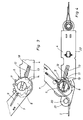
- the tensioning device shown in FIGS. 1-3 is designed as a ratchet with an integrated preload force display device. It is connected to two tension strands 1 and 2 formed by straps.
- the tension cord 1 is connected to a drive element 5 rotatably mounted in side walls 3 and 4.
- the drive part 7 is pivotally mounted on the drive element 5. When the drive part 7 moves in the direction of arrow 10, i.e. counterclockwise, the drive pawl 9 takes the drive element 5 with it.
- the ratchet wheel is held by a locking mechanism which has a plurality of locking elements 12 and 13 which can be brought into engagement with the locking teeth 11 of the ratchet wheel 6.
- the locking elements can be moved out of the hatches of the ratchet teeth 11 of the ratchet wheel 6 by means of control cams 14 when the tension cords 1 and 2 are loosened, as indicated in FIG. 3, against the action of springs 15 and 16, respectively, which act against a transverse yoke 17 support.
- the locking elements 12 and 13 are formed in the case shown by slides, which are guided together in slots 18 of the side walls 3 and 4.
- the ratchet wheel can be locked in positions that differ in angle by a smaller amount than the pitch angle of the teeth of the ratchet wheel.
- a guide member 20 should also be provided at a distance from the drive element 5 for the tension cord 1 connected to the drive element 5.
- This guide member is preferably rotatably mounted in fork-like extensions 21 of the side walls 3 and 4.
- the guide member 20 is positioned such that the tensioning forces introduced into the tensioning device by the tensioning strand are directed essentially parallel to the bearing surface 22 of the tensioning device.
Landscapes
- Engineering & Computer Science (AREA)
- Mechanical Engineering (AREA)
- General Engineering & Computer Science (AREA)
- Transportation (AREA)
- Devices For Conveying Motion By Means Of Endless Flexible Members (AREA)
- Tension Adjustment In Filamentary Materials (AREA)
- Spinning Or Twisting Of Yarns (AREA)
- Hand Tools For Fitting Together And Separating, Or Other Hand Tools (AREA)
- Transmission Devices (AREA)
Claims (8)
Priority Applications (1)
| Application Number | Priority Date | Filing Date | Title |
|---|---|---|---|
| AT84730128T ATE57997T1 (de) | 1983-12-06 | 1984-11-30 | Spannvorrichtung fuer spannstraenge, insbesondere ketten oder gurte. |
Applications Claiming Priority (2)
| Application Number | Priority Date | Filing Date | Title |
|---|---|---|---|
| DE3344487 | 1983-12-06 | ||
| DE3344487A DE3344487C1 (de) | 1983-12-06 | 1983-12-06 | Spannvorrichtung für Spannstränge, insbesondere Ketten oder Gurte |
Publications (4)
| Publication Number | Publication Date |
|---|---|
| EP0145644A2 EP0145644A2 (fr) | 1985-06-19 |
| EP0145644A3 EP0145644A3 (en) | 1987-10-14 |
| EP0145644B1 EP0145644B1 (fr) | 1990-10-31 |
| EP0145644B2 true EP0145644B2 (fr) | 1994-06-15 |
Family
ID=6216428
Family Applications (1)
| Application Number | Title | Priority Date | Filing Date |
|---|---|---|---|
| EP84730128A Expired - Lifetime EP0145644B2 (fr) | 1983-12-06 | 1984-11-30 | Dispositif tendeur, en particulier pour chaînes ou sangles |
Country Status (6)
| Country | Link |
|---|---|
| US (1) | US4570305A (fr) |
| EP (1) | EP0145644B2 (fr) |
| JP (1) | JPS60155377A (fr) |
| AT (1) | ATE57997T1 (fr) |
| AU (1) | AU562331B2 (fr) |
| DE (2) | DE3344487C1 (fr) |
Families Citing this family (21)
| Publication number | Priority date | Publication date | Assignee | Title |
|---|---|---|---|---|
| USD320925S (en) | 1989-07-19 | 1991-10-22 | Robert G. Barbour | Double-locking anchor chain tensioner |
| CA2040850C (fr) * | 1990-05-03 | 1995-09-19 | Hans-Werner Kamper | Ensemble tendeur servant a serrer et a desserrer une bande de tension |
| DE9102777U1 (de) * | 1991-03-08 | 1992-07-02 | Spanset Inter Ag, Oetwil Am See | Spann- und Zurrvorrichtung für Zurrstränge |
| JPH0793887B2 (ja) * | 1990-10-11 | 1995-10-11 | ワイケイケイ株式会社 | ベルトの長さ調節具 |
| US5205020A (en) * | 1991-03-08 | 1993-04-27 | Spanset Inter Ag | Tensioning apparatus for a lashing strap |
| DE19731286C2 (de) * | 1997-07-21 | 1999-07-08 | Huang Han Ching | Spannvorrichtung für Gurte und dergleichen |
| US5778496A (en) * | 1997-09-16 | 1998-07-14 | Huang; Han-Ching | Strapping device |
| US5894638A (en) * | 1998-08-17 | 1999-04-20 | Huang; Han-Ching | Strapping device |
| GB2341888B (en) * | 1998-09-24 | 2000-11-08 | Huang Han Ching | Strap tightening/loosening device |
| US20040104380A1 (en) * | 2002-12-02 | 2004-06-03 | Han-Ching Huang | Force-indicating strap fastener |
| US7207089B2 (en) * | 2003-12-11 | 2007-04-24 | Burton Warren Hanson | Bi-directional load securing ratchet method and apparatus |
| WO2007041752A1 (fr) * | 2005-10-12 | 2007-04-19 | Shang Wang | Tendeur a chaine (ausbinder) |
| CN100532763C (zh) * | 2007-04-18 | 2009-08-26 | 沈伟强 | 手持式电动钢筋扎丝机 |
| US8191208B2 (en) * | 2008-06-06 | 2012-06-05 | Hanson Burton W | Load securing ratchet with anchor attachment system |
| US20130160254A1 (en) * | 2009-04-10 | 2013-06-27 | James Marshall Stoddard | Combination Chain Tensioning Boom and Tensioning Sensor |
| GB201102888D0 (en) | 2011-02-18 | 2011-04-06 | Durand Denis | Improved ratchet strap binder |
| WO2014056545A1 (fr) | 2012-10-12 | 2014-04-17 | O.I. Meyer Holding Ag | Cliquet destiné à une sangle d'arrimage |
| US9898175B2 (en) | 2014-08-05 | 2018-02-20 | Fibar Group S.A. | Home network manager for home automation |
| US11414006B2 (en) * | 2020-08-18 | 2022-08-16 | Nicholas Deplaris | Locking mechanism for tie down locking device |
| CN112483460A (zh) * | 2020-11-26 | 2021-03-12 | 扬州大学 | 一种防止传动轴反转的轴流泵叶轮结构 |
| CN113236711B (zh) * | 2021-04-30 | 2022-09-02 | 神华准格尔能源有限责任公司 | 用于钢丝绳的端部连接件和钢丝绳端部接头的方法 |
Family Cites Families (17)
| Publication number | Priority date | Publication date | Assignee | Title |
|---|---|---|---|---|
| DE8022576U1 (de) * | 1982-02-04 | Eisen-und Drahtwerk Erlau AG, 7080 Aalen | Ratsche zum Spannen von Gurten, Seilen u.dgl. | |
| US1375558A (en) * | 1920-09-03 | 1921-04-19 | Butner William Richardson | Ratchet-chain block |
| US2363138A (en) * | 1943-07-15 | 1944-11-21 | Schuler Engineering Company | Reversible hand-operated windlass |
| US2993680A (en) * | 1960-05-10 | 1961-07-25 | Frank L Davis | Quick adjustment, ratchet tensioned tiedown |
| US3175806A (en) * | 1963-11-04 | 1965-03-30 | Brown Line Corp | Ratchet buckle |
| US3804368A (en) * | 1971-03-04 | 1974-04-16 | Irvin Gb Ltd | Ratchet tensioners |
| GB1337679A (en) * | 1971-03-04 | 1973-11-21 | Irvin Great Britain Ltd | Ratchet tensioners |
| US3749366A (en) * | 1972-05-22 | 1973-07-31 | Kinedyne Corp | Ratchet buckle |
| US3826473A (en) * | 1972-12-26 | 1974-07-30 | Trans Technology Corp | Slidable buckle assembly |
| JPS5128118U (fr) * | 1974-08-22 | 1976-03-01 | ||
| SE408695B (sv) | 1977-10-31 | 1979-07-02 | Goteborgs Bandveveri Ab | Anordning vid organ for atspenning och lasning av sling eller lastband |
| SE412557C (sv) * | 1978-04-28 | 1985-07-15 | Holmbergs Fab Ab Brdr | Bandstreckare |
| US4185360A (en) * | 1978-08-14 | 1980-01-29 | Ancra Corporation | Ratchet buckle for tightening and tensioning strap |
| US4324022A (en) * | 1980-06-16 | 1982-04-13 | Ancra Corporation | Ratchet buckle having reinforcement strengthening means |
| GB2105805B (en) * | 1981-07-10 | 1985-07-03 | Spanset Inter Ag | Ratchet device for tightening belts surrounding loads on trailers |
| CH658823A5 (de) * | 1981-11-06 | 1986-12-15 | Rud Ketten Rieger & Dietz | Spannvorrichtung. |
| DE8229264U1 (de) * | 1982-10-19 | 1983-02-03 | Henssgen Karabinerhaken GmbH, 5603 Wülfrath | Spannvorrichtung fuer zurrgurte od. dgl. |
-
1983
- 1983-12-06 DE DE3344487A patent/DE3344487C1/de not_active Expired
-
1984
- 1984-11-30 DE DE8484730128T patent/DE3483517D1/de not_active Expired - Lifetime
- 1984-11-30 EP EP84730128A patent/EP0145644B2/fr not_active Expired - Lifetime
- 1984-11-30 AT AT84730128T patent/ATE57997T1/de active
- 1984-12-03 US US06/677,163 patent/US4570305A/en not_active Expired - Lifetime
- 1984-12-05 AU AU36331/84A patent/AU562331B2/en not_active Ceased
- 1984-12-06 JP JP59258412A patent/JPS60155377A/ja active Pending
Also Published As
| Publication number | Publication date |
|---|---|
| EP0145644B1 (fr) | 1990-10-31 |
| JPS60155377A (ja) | 1985-08-15 |
| ATE57997T1 (de) | 1990-11-15 |
| AU3633184A (en) | 1985-06-13 |
| EP0145644A2 (fr) | 1985-06-19 |
| EP0145644A3 (en) | 1987-10-14 |
| DE3344487C1 (de) | 1988-09-08 |
| US4570305A (en) | 1986-02-18 |
| AU562331B2 (en) | 1987-06-04 |
| DE3483517D1 (de) | 1990-12-06 |
Similar Documents
| Publication | Publication Date | Title |
|---|---|---|
| EP0145644B2 (fr) | Dispositif tendeur, en particulier pour chaînes ou sangles | |
| EP0020903A1 (fr) | Boucle pour ceinture de sécurité | |
| DE1678400A1 (de) | Umsteuerbare Ratsche | |
| EP0145645B1 (fr) | Dispositif tendeur, en particulier pour chaînes ou sangles | |
| DE4308366A1 (fr) | ||
| DE3686920T2 (de) | Blattfoerdergeraet. | |
| DE3240362A1 (de) | Knarre | |
| EP0489376B1 (fr) | Dispositif tendeur | |
| DE3210723C2 (de) | Farbbandhubvorrichtung für Schreib- oder ähnliche Maschinen | |
| DE456131C (de) | Schaltvorrichtung fuer Wechselgetriebe, insbesondere von Kraftfahrzeugen | |
| DE557478C (de) | Unter der Wirkung einer Feder stehende Spannrolle mit einem den Ruecklauf verhindernden Gesperre | |
| DE2235372A1 (de) | Vorrichtung zur foerderung eines farbbandes in einem drucker | |
| DE3736109C1 (de) | Ratschenschluessel | |
| DE69702420T2 (de) | Vorrichtung zum Heben einer vertikal beweglichen Tür | |
| DE3710894C2 (fr) | ||
| DE2328306C3 (de) | Mechanische Schalteinrichtung mit Schrittschaltwerk | |
| DE2350250C3 (de) | alte- und Umschaltvorrichtung für die Längsbewegung eines kassetierten Farbbandes in Typendruckwerken | |
| DE2504431C2 (de) | Vorrichtung zum Halten einer Bandkassette in einem Kassettenrekorder | |
| DE2514166C2 (de) | Rückstellvorrichtung für ein Zählwerk mit Ziffernrollen | |
| DE2227270B2 (de) | Vorrichtung zum diskontinuierlichen und umkehrbaren drehantrieb der waehltrommeln von mustervorrichtungen | |
| CH405854A (de) | Vorrichtung zum Spannen eines der Drehmomentübertragung dienenden Riemens | |
| DE1436700C (de) | Proportionalschrittschalteinnchtung fur den Wagen einer Schreibmaschine | |
| DE1176057B (de) | Umlauffoerderanlage mit Waehleinrichtungen zum Einstellen des Kennzeichens einer Empfangsstation | |
| DE2316167C2 (de) | Einrichtung zum Ausrichten und Verriegeln eines kugelförmigen Typenträgers | |
| DE4444195C1 (de) | Uhr mit Gewichts- oder Federantrieb |
Legal Events
| Date | Code | Title | Description |
|---|---|---|---|
| PUAI | Public reference made under article 153(3) epc to a published international application that has entered the european phase |
Free format text: ORIGINAL CODE: 0009012 |
|
| AK | Designated contracting states |
Designated state(s): AT CH DE GB IT LI SE |
|
| RTI1 | Title (correction) | ||
| PUAL | Search report despatched |
Free format text: ORIGINAL CODE: 0009013 |
|
| AK | Designated contracting states |
Kind code of ref document: A3 Designated state(s): AT CH DE GB IT LI SE |
|
| 17P | Request for examination filed |
Effective date: 19871211 |
|
| 17Q | First examination report despatched |
Effective date: 19890130 |
|
| GRAA | (expected) grant |
Free format text: ORIGINAL CODE: 0009210 |
|
| AK | Designated contracting states |
Kind code of ref document: B1 Designated state(s): AT CH DE GB IT LI SE |
|
| REF | Corresponds to: |
Ref document number: 57997 Country of ref document: AT Date of ref document: 19901115 Kind code of ref document: T |
|
| ITF | It: translation for a ep patent filed | ||
| REF | Corresponds to: |
Ref document number: 3483517 Country of ref document: DE Date of ref document: 19901206 |
|
| GBT | Gb: translation of ep patent filed (gb section 77(6)(a)/1977) | ||
| PLBI | Opposition filed |
Free format text: ORIGINAL CODE: 0009260 |
|
| 26 | Opposition filed |
Opponent name: DANKERT, DIETRICH DIPL.-ING. Effective date: 19910731 |
|
| ITTA | It: last paid annual fee | ||
| PUAH | Patent maintained in amended form |
Free format text: ORIGINAL CODE: 0009272 |
|
| STAA | Information on the status of an ep patent application or granted ep patent |
Free format text: STATUS: PATENT MAINTAINED AS AMENDED |
|
| 27A | Patent maintained in amended form |
Effective date: 19940615 |
|
| AK | Designated contracting states |
Kind code of ref document: B2 Designated state(s): AT CH DE GB IT LI SE |
|
| REG | Reference to a national code |
Ref country code: CH Ref legal event code: AEN |
|
| GBTA | Gb: translation of amended ep patent filed (gb section 77(6)(b)/1977) |
Effective date: 19940803 |
|
| ITF | It: translation for a ep patent filed | ||
| EAL | Se: european patent in force in sweden |
Ref document number: 84730128.0 |
|
| PGFP | Annual fee paid to national office [announced via postgrant information from national office to epo] |
Ref country code: GB Payment date: 19971114 Year of fee payment: 14 |
|
| PGFP | Annual fee paid to national office [announced via postgrant information from national office to epo] |
Ref country code: SE Payment date: 19971121 Year of fee payment: 14 Ref country code: AT Payment date: 19971121 Year of fee payment: 14 |
|
| PGFP | Annual fee paid to national office [announced via postgrant information from national office to epo] |
Ref country code: CH Payment date: 19971125 Year of fee payment: 14 |
|
| PG25 | Lapsed in a contracting state [announced via postgrant information from national office to epo] |
Ref country code: LI Free format text: LAPSE BECAUSE OF NON-PAYMENT OF DUE FEES Effective date: 19981130 Ref country code: GB Free format text: LAPSE BECAUSE OF NON-PAYMENT OF DUE FEES Effective date: 19981130 Ref country code: CH Free format text: LAPSE BECAUSE OF NON-PAYMENT OF DUE FEES Effective date: 19981130 Ref country code: AT Free format text: LAPSE BECAUSE OF NON-PAYMENT OF DUE FEES Effective date: 19981130 |
|
| PG25 | Lapsed in a contracting state [announced via postgrant information from national office to epo] |
Ref country code: SE Free format text: LAPSE BECAUSE OF NON-PAYMENT OF DUE FEES Effective date: 19981201 |
|
| REG | Reference to a national code |
Ref country code: CH Ref legal event code: PL |
|
| GBPC | Gb: european patent ceased through non-payment of renewal fee |
Effective date: 19981130 |
|
| PGFP | Annual fee paid to national office [announced via postgrant information from national office to epo] |
Ref country code: DE Payment date: 19991217 Year of fee payment: 16 |
|
| PG25 | Lapsed in a contracting state [announced via postgrant information from national office to epo] |
Ref country code: DE Free format text: LAPSE BECAUSE OF NON-PAYMENT OF DUE FEES Effective date: 20010801 |
|
| PLAB | Opposition data, opponent's data or that of the opponent's representative modified |
Free format text: ORIGINAL CODE: 0009299OPPO |