EP0145644B2 - Device for tensioning lines, especially chains or belts - Google Patents
Device for tensioning lines, especially chains or belts Download PDFInfo
- Publication number
- EP0145644B2 EP0145644B2 EP84730128A EP84730128A EP0145644B2 EP 0145644 B2 EP0145644 B2 EP 0145644B2 EP 84730128 A EP84730128 A EP 84730128A EP 84730128 A EP84730128 A EP 84730128A EP 0145644 B2 EP0145644 B2 EP 0145644B2
- Authority
- EP
- European Patent Office
- Prior art keywords
- ratchet wheel
- tensioning device
- teeth
- drive
- drive element
- Prior art date
- Legal status (The legal status is an assumption and is not a legal conclusion. Google has not performed a legal analysis and makes no representation as to the accuracy of the status listed.)
- Expired - Lifetime
Links
Images

Classifications
-
- A—HUMAN NECESSITIES
- A44—HABERDASHERY; JEWELLERY
- A44B—BUTTONS, PINS, BUCKLES, SLIDE FASTENERS, OR THE LIKE
- A44B11/00—Buckles; Similar fasteners for interconnecting straps or the like, e.g. for safety belts
- A44B11/02—Buckles; Similar fasteners for interconnecting straps or the like, e.g. for safety belts frictionally engaging surface of straps
- A44B11/06—Buckles; Similar fasteners for interconnecting straps or the like, e.g. for safety belts frictionally engaging surface of straps with clamping devices
- A44B11/12—Buckles; Similar fasteners for interconnecting straps or the like, e.g. for safety belts frictionally engaging surface of straps with clamping devices turnable clamp
- A44B11/125—Buckles; Similar fasteners for interconnecting straps or the like, e.g. for safety belts frictionally engaging surface of straps with clamping devices turnable clamp with strap tightening means
-
- B—PERFORMING OPERATIONS; TRANSPORTING
- B60—VEHICLES IN GENERAL
- B60P—VEHICLES ADAPTED FOR LOAD TRANSPORTATION OR TO TRANSPORT, TO CARRY, OR TO COMPRISE SPECIAL LOADS OR OBJECTS
- B60P7/00—Securing or covering of load on vehicles
- B60P7/06—Securing of load
- B60P7/08—Securing to the vehicle floor or sides
- B60P7/0823—Straps; Tighteners
- B60P7/083—Tensioning by repetetive movement of an actuating member
-
- F—MECHANICAL ENGINEERING; LIGHTING; HEATING; WEAPONS; BLASTING
- F16—ENGINEERING ELEMENTS AND UNITS; GENERAL MEASURES FOR PRODUCING AND MAINTAINING EFFECTIVE FUNCTIONING OF MACHINES OR INSTALLATIONS; THERMAL INSULATION IN GENERAL
- F16G—BELTS, CABLES, OR ROPES, PREDOMINANTLY USED FOR DRIVING PURPOSES; CHAINS; FITTINGS PREDOMINANTLY USED THEREFOR
- F16G11/00—Means for fastening cables or ropes to one another or to other objects; Caps or sleeves for fixing on cables or ropes
- F16G11/12—Connections or attachments, e.g. turnbuckles, adapted for straining of cables, ropes, or wire
-
- Y—GENERAL TAGGING OF NEW TECHNOLOGICAL DEVELOPMENTS; GENERAL TAGGING OF CROSS-SECTIONAL TECHNOLOGIES SPANNING OVER SEVERAL SECTIONS OF THE IPC; TECHNICAL SUBJECTS COVERED BY FORMER USPC CROSS-REFERENCE ART COLLECTIONS [XRACs] AND DIGESTS
- Y10—TECHNICAL SUBJECTS COVERED BY FORMER USPC
- Y10S—TECHNICAL SUBJECTS COVERED BY FORMER USPC CROSS-REFERENCE ART COLLECTIONS [XRACs] AND DIGESTS
- Y10S24/00—Buckles, buttons, clasps
- Y10S24/909—Winders for flexible material
-
- Y—GENERAL TAGGING OF NEW TECHNOLOGICAL DEVELOPMENTS; GENERAL TAGGING OF CROSS-SECTIONAL TECHNOLOGIES SPANNING OVER SEVERAL SECTIONS OF THE IPC; TECHNICAL SUBJECTS COVERED BY FORMER USPC CROSS-REFERENCE ART COLLECTIONS [XRACs] AND DIGESTS
- Y10—TECHNICAL SUBJECTS COVERED BY FORMER USPC
- Y10T—TECHNICAL SUBJECTS COVERED BY FORMER US CLASSIFICATION
- Y10T24/00—Buckles, buttons, clasps, etc.
- Y10T24/21—Strap tighteners
- Y10T24/2175—Cargo tie down
Definitions
- the invention relates to a tensioning device according to the preamble of claim 1.
- a jig of the type under consideration is e.g. known from US-A-4 199 182 (FR-A-2 407 097).
- a locking mechanism is assigned to the teeth of the ratchet wheel, the locking element of which is formed by a slide which can be moved back and forth against the action of a spring in opposite side walls of the device.
- tensioning devices also known as lashing ratchets
- ratchet pawls In order to reduce the locking jumps for a given size and number of teeth of a ratchet wheel, several ratchet pawls have been used in a ratchet lock known from LUEGER, Lexikon dertechnik, Vol. 1, p. 530, which are pivotably mounted on axes arranged one behind the other in the circumferential direction of the ratchet wheel are.
- the invention has for its object to provide a tensioning device of the type under consideration, which makes it possible, despite the retention of conventional ratchet wheels with a comparatively large pitch angle, the loss of preload that occurs due to a backward rotation of the ratchet wheel until it is locked, than in the known tensioning devices of the relevant type to keep, and this without the disadvantages aggravating the handling of the known jig.
- the tensioning device according to the invention has the advantage that known prestressing devices can be held in a simple manner without substantially changing the basic structure with these prestressing forces, which deviate far less from the maximum prestressing forces that can be applied than was previously the case.
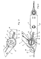
- the tensioning device shown in FIGS. 1-3 is designed as a ratchet with an integrated preload force display device. It is connected to two tension strands 1 and 2 formed by straps.
- the tension cord 1 is connected to a drive element 5 rotatably mounted in side walls 3 and 4.
- the drive part 7 is pivotally mounted on the drive element 5. When the drive part 7 moves in the direction of arrow 10, i.e. counterclockwise, the drive pawl 9 takes the drive element 5 with it.
- the ratchet wheel is held by a locking mechanism which has a plurality of locking elements 12 and 13 which can be brought into engagement with the locking teeth 11 of the ratchet wheel 6.
- the locking elements can be moved out of the hatches of the ratchet teeth 11 of the ratchet wheel 6 by means of control cams 14 when the tension cords 1 and 2 are loosened, as indicated in FIG. 3, against the action of springs 15 and 16, respectively, which act against a transverse yoke 17 support.
- the locking elements 12 and 13 are formed in the case shown by slides, which are guided together in slots 18 of the side walls 3 and 4.
- the ratchet wheel can be locked in positions that differ in angle by a smaller amount than the pitch angle of the teeth of the ratchet wheel.
- a guide member 20 should also be provided at a distance from the drive element 5 for the tension cord 1 connected to the drive element 5.
- This guide member is preferably rotatably mounted in fork-like extensions 21 of the side walls 3 and 4.
- the guide member 20 is positioned such that the tensioning forces introduced into the tensioning device by the tensioning strand are directed essentially parallel to the bearing surface 22 of the tensioning device.
Landscapes
- Engineering & Computer Science (AREA)
- Mechanical Engineering (AREA)
- General Engineering & Computer Science (AREA)
- Transportation (AREA)
- Devices For Conveying Motion By Means Of Endless Flexible Members (AREA)
- Tension Adjustment In Filamentary Materials (AREA)
- Spinning Or Twisting Of Yarns (AREA)
- Hand Tools For Fitting Together And Separating, Or Other Hand Tools (AREA)
- Transmission Devices (AREA)
Abstract
Description
Die Erfindung betrifft eine Spannvorrichtung nach dem Oberbegriff des Patentanspruches 1.The invention relates to a tensioning device according to the preamble of claim 1.
Eine Spannvorrichtung der in Betracht gezogenen Art ist z.B. aus der US-A-4 199 182 (FR-A-2 407 097) bekannt. Bei der bekannten Spannvorrichtung ist den Zähnen des Klinkenrades ein Sperrmechanismus zugeordnet, dessen Sperrelement von einem gegen die Wirkung einer Feder in sich gegenüberliegenden Seitenwänden der Vorrichtung geführten, hin- und herbewegbaren Schieber gebildet wird. Bei derartigen auch als Zurr-Ratschen bezeichneten Spannvorrichtungen sind dem Durchmesser der Klinkenräder bauliche Grenzen gesetzt und die Zahl ihrer Zähne ist aus Festigkeitsgründen begrenzt. Sie beträgt regelmäßig 11, was einem Zahnteilungswinkel von etwa 33° entspricht. Ein derart großer Teilungswinkel macht es häufig unmöglich, die durch Betätigen des im allgemeinen von einem Schwenkhebel gebildeten Antriebsteils an sich erreichbare hohe Vorspannkraft auch nur annähernd zu haltten, da einerseits zum Einrasten der Sperrklinke in die nächstfolgende Zahnlücke des Klinkenrades noch eine Weiterbewegung des Antriebsteiles nötig wäre, die jedoch kräftemäßig nicht zu bewältigen ist und andererseits beim Einrasten der Sperrklinke in die erreichte Zahnlücke eine Rückdrehung des Klinkenrades von im ungünstigsten Fall nur wenig weniger als 33° in Kauf genommen werden muß.A jig of the type under consideration is e.g. known from US-A-4 199 182 (FR-A-2 407 097). In the known tensioning device, a locking mechanism is assigned to the teeth of the ratchet wheel, the locking element of which is formed by a slide which can be moved back and forth against the action of a spring in opposite side walls of the device. In such tensioning devices, also known as lashing ratchets, there are structural limits to the diameter of the ratchet wheels and the number of their teeth is limited for reasons of strength. It is regularly 11, which corresponds to a tooth pitch angle of approximately 33 °. Such a large pitch angle often makes it impossible to even approximately maintain the high pretensioning force that can be achieved by actuating the drive part, which is generally formed by a swivel lever, since, on the one hand, a further movement of the drive part would be necessary to snap the pawl into the next tooth gap of the ratchet wheel which, however, cannot be mastered in terms of strength and, on the other hand, when the pawl snaps into the tooth gap reached, a reverse rotation of the ratchet wheel of in the worst case only a little less than 33 ° has to be accepted.
Um bei vorgegebener Größe und Zähnezahl eines Klinkenrades die Sperrsprünge zu verkleinern, hat man bei einer aus LUEGER, Lexikon der Technik, Bd. 1, S. 530, bekannten Klinkensperre mehrere Klinken verwendet, die schwenkbar auf in Umfangsrichtung des Klinkenrades betrachtet hintereinander angeordneten Achsen gelagert sind. Eine derartige Anordnung setzt nicht nur das Vorhandensein stabiler Lager für die Achsen der Klinken voraus, sondern beansprucht auch vergleichsweise viel Raum, so daß sie für Spannvorrichtungen der hier zur Diskussion stehenden Art praktisch ungeeignet ist, zumal hierein von einem Spannhebel gebildetes, mit einer verschiebbaren Antriebsklinke versehenes Antriebsteil verwendet wird, das zusätzlich die Aufgabe hat, die Wirksamkeit des Sperrmechanismus bei Bedarf aufzuheben.In order to reduce the locking jumps for a given size and number of teeth of a ratchet wheel, several ratchet pawls have been used in a ratchet lock known from LUEGER, Lexikon der Technik, Vol. 1, p. 530, which are pivotably mounted on axes arranged one behind the other in the circumferential direction of the ratchet wheel are. Such an arrangement not only presupposes the presence of stable bearings for the axes of the pawls, but also takes up a comparatively large amount of space, so that it is practically unsuitable for tensioning devices of the type under discussion here, especially since this is formed by a tensioning lever with a displaceable drive pawl Provided drive part is used, which also has the task of canceling the effectiveness of the locking mechanism if necessary.
Der Erfindung liegt die Aufgabe zugrunde, eine Spannvorrichtung der in Betracht gezogenen Gattung zu schaffen, die es trotz Beibehaltung üblicher Klinkenräder mit einem vergleichsweise großen Teilungswinkel ermöglicht, die durch eine Rückdrehung des Klinkenrades bis zu dessen Arretierung auftretenden Vorspannkaftverluste kleiner als bei den bekannten Spannvorrichtungen einschlägiger Art zu halten, und dies ohne Inkaufnahme von die Handhabung der bekannten Spannvorrichtung erschwerenden Nachteilen.The invention has for its object to provide a tensioning device of the type under consideration, which makes it possible, despite the retention of conventional ratchet wheels with a comparatively large pitch angle, the loss of preload that occurs due to a backward rotation of the ratchet wheel until it is locked, than in the known tensioning devices of the relevant type to keep, and this without the disadvantages aggravating the handling of the known jig.
Diese Aufgabe wird erfindungsgemäß durch die Merkmale des Patentanspruches 1 gelöst.This object is achieved by the features of claim 1.
Die erfindungsgemässe Spannvorrichtung bietet den Vorteil, daß auf einfache Weise ohne wesentliche Veränderung des Grundaufbaues bekannter Spannvorrichtungen mit diesen Vorspannkräfte gehalten werden können, die weit weniger von den maximal aufbringbaren Vorspannkräften abweichen, als dies bisher der Fall war.The tensioning device according to the invention has the advantage that known prestressing devices can be held in a simple manner without substantially changing the basic structure with these prestressing forces, which deviate far less from the maximum prestressing forces that can be applied than was previously the case.
Um auch die Vorspannkräfte bezüglich ihrer Maximalwerte steigern zu können, empfiehlt es sich, die Rastzähne des Klinkenrades so auszubilden, wie dies in Unteranspruch 4 beschrieben ist.In order to also be able to increase the pretensioning forces with regard to their maximum values, it is advisable to design the ratchet teeth of the ratchet wheel as described in
Weitere Einzelheiten und Merkmale der erfindungsgemässen Spannvorrichtung ergeben sich aus den weiteren Unteransprüchen, den beigefügten Figuren und der nachfolgenden Beschreibung. Es zeigen
- Figur 1 die Seitenansicht einer Spannvorrichtung,
Figur 2 eine Draufsicht auf die Spannvorrichtung gemäßt Figur 1,Figur 3 eine Einzelheit der Spannvorrichtung gemäß Figuren 1 und 2 bei veränderter Stellung des Antriebsteiles,Figur 4 ein modifiziertes Ausführungsbeispiel einer Spannvorrichtung.
- FIG. 1 shows the side view of a tensioning device,
- FIG. 2 shows a top view of the tensioning device according to FIG. 1,
- FIG. 3 shows a detail of the tensioning device according to FIGS. 1 and 2 when the drive part is in a different position,
- Figure 4 shows a modified embodiment of a clamping device.
Die in den Figuren 1-3 dargestellte Spannvorrichtung ist als Ratsche mit einer integrierten Vorspannkraftanzeigevorrichtung ausgebildet. Sie steht mit zwei v on Gurten gebildeten Spannsträngen 1 und 2 in Verbindung. Der Spannstrang 1 ist mit einem drehbar in Seitenwänden 3 und 4 gelagerten Antriebselement 5 verbunden. Zum Antrieb des drehfest mit zwei Klinkenräder 6 verbundenen Antriebselements dient ein Antriebsteil 7, das im dargestellten Fall von einem Schwenkhebel gebildet wird und in dem gegen die Wirkung einer Feder 8 verschiebbar eine Antriebsklinke 9 geführt ist. Das Antriebsteil 7 ist schwenkbar auf dem Antriebselement 5 gelagert. Bei Bewegung des Antriebsteiles 7 in Richtung des Pfeiles 10, d.h. entgegen dem Uhrzeigesinn, nimmt die Antriebsklinke 9 das Antriebselement 5 mit. Beim Zurückführen des Antriebsteiles 7 wird Klinkenrad dagegen von einem Sperrmechanismus gehalten, der mehrere mit den Rastzähnen 11 des Klinkenrades 6 in Eingriff bringbare Sperrelemente 12 und 13 aufweist. Die Sperrelemente lassen sich beim Lösen der Spannstränge 1 und 2, wie in Figur 3 angedeutet, durch Steuerkurven 14 gemeinsam aus den Lükken der Rastzähne 11 des Klinkenrades 6 herausbewegen, und zwar gegen die Wirkung von Federn 15 bzw. 16, die sich gegen ein Querjoch 17 abstützen. Die Sperrelemente 12 und 13 werden im dargestellten Fall von Schiebern gebildet, die gemeinsam in Schlitzen 18 der Seitenwände 3 und 4 geführt sind.The tensioning device shown in FIGS. 1-3 is designed as a ratchet with an integrated preload force display device. It is connected to two
Dadurch, daß jeder Lücke zwischen den Rastzähnen 11 des Klinkenrades 6 mehrere Sperrelemente 12, 13 zugeordnet sind, läßt sich das Klinkenrad in Positionen arretieren, die winkelmässig um einen geringeren Betrag voneinander abweichen als der Teilungswinkel der Zähne des Klinkenrades.Characterized in that each gap between the
Um möglichst grosse Vorspannkräfte realisieren zu können, empfiehlt es sich, die Rastzähne 11 des Klinkenrades 6 so anzuordnen, daß der Zahnrücken 19 des in der Sperrstellung des Klinkenrades 6 jeweils mit einem der Sperrelemente 12 oder 13 in Eingriff stehenden Rastzahnes 11 dem freien Ende des Antriebsteiles 7 abgewandt ist, wie dies die Figur 4 zeigt. In einem solchen Falle sollte außerdem im Abstand vom Antriebselement 5 ein Führungsorgan 20 für den mit dem Antriebselement 5 verbundenen Spannstrang 1 vorgesehen sein. Dieses Führugsorgan ist vorzugsweise drehbar in gabelartigen Verlängerungen 21 der Seitenwände 3 und 4 gelagert.In order to be able to realize the greatest possible preload forces, it is advisable to arrange the
Das Führungsorgan 20 ist so positioniert, daß die durch den Spannstrang in die Spannvorrichtung eingeleiteten Spannkräfte im wesentlichen parallel zur Auflagefläche 22 der Spannvorrichtung gerichtet sind.The
Claims (8)
Priority Applications (1)
| Application Number | Priority Date | Filing Date | Title |
|---|---|---|---|
| AT84730128T ATE57997T1 (en) | 1983-12-06 | 1984-11-30 | TENSIONING DEVICE FOR TENSIONING RODS, ESPECIALLY CHAINS OR BELTS. |
Applications Claiming Priority (2)
| Application Number | Priority Date | Filing Date | Title |
|---|---|---|---|
| DE3344487 | 1983-12-06 | ||
| DE3344487A DE3344487C1 (en) | 1983-12-06 | 1983-12-06 | Tensioning device for tension cords, in particular chains or belts |
Publications (4)
| Publication Number | Publication Date |
|---|---|
| EP0145644A2 EP0145644A2 (en) | 1985-06-19 |
| EP0145644A3 EP0145644A3 (en) | 1987-10-14 |
| EP0145644B1 EP0145644B1 (en) | 1990-10-31 |
| EP0145644B2 true EP0145644B2 (en) | 1994-06-15 |
Family
ID=6216428
Family Applications (1)
| Application Number | Title | Priority Date | Filing Date |
|---|---|---|---|
| EP84730128A Expired - Lifetime EP0145644B2 (en) | 1983-12-06 | 1984-11-30 | Device for tensioning lines, especially chains or belts |
Country Status (6)
| Country | Link |
|---|---|
| US (1) | US4570305A (en) |
| EP (1) | EP0145644B2 (en) |
| JP (1) | JPS60155377A (en) |
| AT (1) | ATE57997T1 (en) |
| AU (1) | AU562331B2 (en) |
| DE (2) | DE3344487C1 (en) |
Families Citing this family (21)
| Publication number | Priority date | Publication date | Assignee | Title |
|---|---|---|---|---|
| USD320925S (en) | 1989-07-19 | 1991-10-22 | Robert G. Barbour | Double-locking anchor chain tensioner |
| DE9102777U1 (en) * | 1991-03-08 | 1992-07-02 | Spanset Inter Ag, Oetwil Am See | Tensioning and lashing device for lashing ropes |
| CA2040850C (en) * | 1990-05-03 | 1995-09-19 | Hans-Werner Kamper | Tensioning assembly for the stepwise tightening and releasing of a tensioning strap |
| JPH0793887B2 (en) * | 1990-10-11 | 1995-10-11 | ワイケイケイ株式会社 | Belt length adjuster |
| US5205020A (en) * | 1991-03-08 | 1993-04-27 | Spanset Inter Ag | Tensioning apparatus for a lashing strap |
| DE19731286C2 (en) * | 1997-07-21 | 1999-07-08 | Huang Han Ching | Tensioning device for belts and the like |
| US5778496A (en) * | 1997-09-16 | 1998-07-14 | Huang; Han-Ching | Strapping device |
| US5894638A (en) * | 1998-08-17 | 1999-04-20 | Huang; Han-Ching | Strapping device |
| GB2341888B (en) * | 1998-09-24 | 2000-11-08 | Huang Han Ching | Strap tightening/loosening device |
| US20040104380A1 (en) * | 2002-12-02 | 2004-06-03 | Han-Ching Huang | Force-indicating strap fastener |
| US7207089B2 (en) * | 2003-12-11 | 2007-04-24 | Burton Warren Hanson | Bi-directional load securing ratchet method and apparatus |
| CA2622269A1 (en) * | 2005-10-12 | 2007-04-19 | Shang Wang | Chain load binder (ausbinder) |
| CN100532763C (en) * | 2007-04-18 | 2009-08-26 | 沈伟强 | Hand-hold electric reinforced bar tying machine |
| US8191208B2 (en) * | 2008-06-06 | 2012-06-05 | Hanson Burton W | Load securing ratchet with anchor attachment system |
| US20130160254A1 (en) * | 2009-04-10 | 2013-06-27 | James Marshall Stoddard | Combination Chain Tensioning Boom and Tensioning Sensor |
| GB201102888D0 (en) | 2011-02-18 | 2011-04-06 | Durand Denis | Improved ratchet strap binder |
| WO2014056545A1 (en) | 2012-10-12 | 2014-04-17 | O.I. Meyer Holding Ag | Ratchet for a lashing strap |
| US9898175B2 (en) | 2014-08-05 | 2018-02-20 | Fibar Group S.A. | Home network manager for home automation |
| US11414006B2 (en) * | 2020-08-18 | 2022-08-16 | Nicholas Deplaris | Locking mechanism for tie down locking device |
| CN112483460A (en) * | 2020-11-26 | 2021-03-12 | 扬州大学 | Axial flow pump impeller structure for preventing transmission shaft from reversing |
| CN113236711B (en) * | 2021-04-30 | 2022-09-02 | 神华准格尔能源有限责任公司 | End connection for a steel cord and method of making a steel cord end connection |
Family Cites Families (17)
| Publication number | Priority date | Publication date | Assignee | Title |
|---|---|---|---|---|
| DE8022576U1 (en) * | 1982-02-04 | Eisen-und Drahtwerk Erlau AG, 7080 Aalen | Ratchet for tensioning belts, ropes, etc. | |
| US1375558A (en) * | 1920-09-03 | 1921-04-19 | Butner William Richardson | Ratchet-chain block |
| US2363138A (en) * | 1943-07-15 | 1944-11-21 | Schuler Engineering Company | Reversible hand-operated windlass |
| US2993680A (en) * | 1960-05-10 | 1961-07-25 | Frank L Davis | Quick adjustment, ratchet tensioned tiedown |
| US3175806A (en) * | 1963-11-04 | 1965-03-30 | Brown Line Corp | Ratchet buckle |
| ZA721341B (en) * | 1971-03-04 | 1972-11-29 | Irvan Great Britain Ltd | Improvements in or relating to ratchet tensioners |
| GB1337679A (en) * | 1971-03-04 | 1973-11-21 | Irvin Great Britain Ltd | Ratchet tensioners |
| US3749366A (en) * | 1972-05-22 | 1973-07-31 | Kinedyne Corp | Ratchet buckle |
| US3826473A (en) * | 1972-12-26 | 1974-07-30 | Trans Technology Corp | Slidable buckle assembly |
| JPS5128118U (en) * | 1974-08-22 | 1976-03-01 | ||
| SE408695B (en) | 1977-10-31 | 1979-07-02 | Goteborgs Bandveveri Ab | DEVICE FOR BODY FOR TENSIONING AND LOADING OF SLING OR LOADING |
| SE412557C (en) * | 1978-04-28 | 1985-07-15 | Holmbergs Fab Ab Brdr | BANDSTRECKARE |
| US4185360A (en) * | 1978-08-14 | 1980-01-29 | Ancra Corporation | Ratchet buckle for tightening and tensioning strap |
| US4324022A (en) * | 1980-06-16 | 1982-04-13 | Ancra Corporation | Ratchet buckle having reinforcement strengthening means |
| GB2105805B (en) * | 1981-07-10 | 1985-07-03 | Spanset Inter Ag | Ratchet device for tightening belts surrounding loads on trailers |
| CH658823A5 (en) * | 1981-11-06 | 1986-12-15 | Rud Ketten Rieger & Dietz | CLAMPING DEVICE. |
| DE8229264U1 (en) * | 1982-10-19 | 1983-02-03 | Henssgen Karabinerhaken GmbH, 5603 Wülfrath | TENSIONER FOR LASHING STRAPS OD. DGL. |
-
1983
- 1983-12-06 DE DE3344487A patent/DE3344487C1/en not_active Expired
-
1984
- 1984-11-30 EP EP84730128A patent/EP0145644B2/en not_active Expired - Lifetime
- 1984-11-30 DE DE8484730128T patent/DE3483517D1/en not_active Expired - Lifetime
- 1984-11-30 AT AT84730128T patent/ATE57997T1/en active
- 1984-12-03 US US06/677,163 patent/US4570305A/en not_active Expired - Lifetime
- 1984-12-05 AU AU36331/84A patent/AU562331B2/en not_active Ceased
- 1984-12-06 JP JP59258412A patent/JPS60155377A/en active Pending
Also Published As
| Publication number | Publication date |
|---|---|
| JPS60155377A (en) | 1985-08-15 |
| US4570305A (en) | 1986-02-18 |
| EP0145644A3 (en) | 1987-10-14 |
| AU562331B2 (en) | 1987-06-04 |
| DE3483517D1 (en) | 1990-12-06 |
| AU3633184A (en) | 1985-06-13 |
| EP0145644B1 (en) | 1990-10-31 |
| ATE57997T1 (en) | 1990-11-15 |
| DE3344487C1 (en) | 1988-09-08 |
| EP0145644A2 (en) | 1985-06-19 |
Similar Documents
| Publication | Publication Date | Title |
|---|---|---|
| EP0145644B2 (en) | Device for tensioning lines, especially chains or belts | |
| EP0020903A1 (en) | Buckle for a safety belt | |
| DE1678400A1 (en) | Reversible ratchet | |
| EP0145645B1 (en) | Device for tensioning lines, especially chains or belts | |
| DE4308366A1 (en) | ||
| DE3686920T2 (en) | SHEET FEEDER. | |
| DE3240362A1 (en) | Creak | |
| EP0489376B1 (en) | Tensioning device | |
| DE3210723C2 (en) | Ribbon lifting device for writing or similar machines | |
| DE456131C (en) | Switching device for change gears, especially of motor vehicles | |
| DE557478C (en) | Tensioning pulley, under the action of a spring, with a locking mechanism preventing backward movement | |
| DE2235372A1 (en) | DEVICE FOR PROMOTING A RIBBON IN A PRINTER | |
| DE3736109C1 (en) | Ratchet wrench | |
| DE69702420T2 (en) | Device for lifting a vertically movable door | |
| AT524051A4 (en) | Device for shifting transport containers between a stack of containers and a container rack | |
| DE3710894C2 (en) | ||
| DE2328306C3 (en) | Mechanical switching device with stepping mechanism | |
| DE2350250C3 (en) | old and switching device for the longitudinal movement of a cassette ink ribbon in type printing units | |
| DE2504431C2 (en) | Device for holding a tape cassette in a cassette recorder | |
| DE2514166C2 (en) | Reset device for a counter with number rollers | |
| CH405854A (en) | Device for tensioning a belt used for torque transmission | |
| DE1436700C (en) | Proportional stepping device for the car of a typewriter | |
| DE1176057B (en) | Circulating conveyor system with selection devices for setting the identification of a receiving station | |
| DE2316167C2 (en) | Device for aligning and locking a spherical type carrier | |
| DE4444195C1 (en) | Mechanical clock mechanism using weights or spring drive |
Legal Events
| Date | Code | Title | Description |
|---|---|---|---|
| PUAI | Public reference made under article 153(3) epc to a published international application that has entered the european phase |
Free format text: ORIGINAL CODE: 0009012 |
|
| AK | Designated contracting states |
Designated state(s): AT CH DE GB IT LI SE |
|
| RTI1 | Title (correction) | ||
| PUAL | Search report despatched |
Free format text: ORIGINAL CODE: 0009013 |
|
| AK | Designated contracting states |
Kind code of ref document: A3 Designated state(s): AT CH DE GB IT LI SE |
|
| 17P | Request for examination filed |
Effective date: 19871211 |
|
| 17Q | First examination report despatched |
Effective date: 19890130 |
|
| GRAA | (expected) grant |
Free format text: ORIGINAL CODE: 0009210 |
|
| AK | Designated contracting states |
Kind code of ref document: B1 Designated state(s): AT CH DE GB IT LI SE |
|
| REF | Corresponds to: |
Ref document number: 57997 Country of ref document: AT Date of ref document: 19901115 Kind code of ref document: T |
|
| ITF | It: translation for a ep patent filed | ||
| REF | Corresponds to: |
Ref document number: 3483517 Country of ref document: DE Date of ref document: 19901206 |
|
| GBT | Gb: translation of ep patent filed (gb section 77(6)(a)/1977) | ||
| PLBI | Opposition filed |
Free format text: ORIGINAL CODE: 0009260 |
|
| 26 | Opposition filed |
Opponent name: DANKERT, DIETRICH DIPL.-ING. Effective date: 19910731 |
|
| ITTA | It: last paid annual fee | ||
| PUAH | Patent maintained in amended form |
Free format text: ORIGINAL CODE: 0009272 |
|
| STAA | Information on the status of an ep patent application or granted ep patent |
Free format text: STATUS: PATENT MAINTAINED AS AMENDED |
|
| 27A | Patent maintained in amended form |
Effective date: 19940615 |
|
| AK | Designated contracting states |
Kind code of ref document: B2 Designated state(s): AT CH DE GB IT LI SE |
|
| REG | Reference to a national code |
Ref country code: CH Ref legal event code: AEN |
|
| GBTA | Gb: translation of amended ep patent filed (gb section 77(6)(b)/1977) |
Effective date: 19940803 |
|
| ITF | It: translation for a ep patent filed | ||
| EAL | Se: european patent in force in sweden |
Ref document number: 84730128.0 |
|
| PGFP | Annual fee paid to national office [announced via postgrant information from national office to epo] |
Ref country code: GB Payment date: 19971114 Year of fee payment: 14 |
|
| PGFP | Annual fee paid to national office [announced via postgrant information from national office to epo] |
Ref country code: SE Payment date: 19971121 Year of fee payment: 14 Ref country code: AT Payment date: 19971121 Year of fee payment: 14 |
|
| PGFP | Annual fee paid to national office [announced via postgrant information from national office to epo] |
Ref country code: CH Payment date: 19971125 Year of fee payment: 14 |
|
| PG25 | Lapsed in a contracting state [announced via postgrant information from national office to epo] |
Ref country code: LI Free format text: LAPSE BECAUSE OF NON-PAYMENT OF DUE FEES Effective date: 19981130 Ref country code: GB Free format text: LAPSE BECAUSE OF NON-PAYMENT OF DUE FEES Effective date: 19981130 Ref country code: CH Free format text: LAPSE BECAUSE OF NON-PAYMENT OF DUE FEES Effective date: 19981130 Ref country code: AT Free format text: LAPSE BECAUSE OF NON-PAYMENT OF DUE FEES Effective date: 19981130 |
|
| PG25 | Lapsed in a contracting state [announced via postgrant information from national office to epo] |
Ref country code: SE Free format text: LAPSE BECAUSE OF NON-PAYMENT OF DUE FEES Effective date: 19981201 |
|
| REG | Reference to a national code |
Ref country code: CH Ref legal event code: PL |
|
| GBPC | Gb: european patent ceased through non-payment of renewal fee |
Effective date: 19981130 |
|
| PGFP | Annual fee paid to national office [announced via postgrant information from national office to epo] |
Ref country code: DE Payment date: 19991217 Year of fee payment: 16 |
|
| PG25 | Lapsed in a contracting state [announced via postgrant information from national office to epo] |
Ref country code: DE Free format text: LAPSE BECAUSE OF NON-PAYMENT OF DUE FEES Effective date: 20010801 |
|
| PLAB | Opposition data, opponent's data or that of the opponent's representative modified |
Free format text: ORIGINAL CODE: 0009299OPPO |