EP0144030B1 - Profilrohr für die Herstellung von leicht montier- und wieder demontierbaren Aufbauten - Google Patents
Profilrohr für die Herstellung von leicht montier- und wieder demontierbaren Aufbauten Download PDFInfo
- Publication number
- EP0144030B1 EP0144030B1 EP84113921A EP84113921A EP0144030B1 EP 0144030 B1 EP0144030 B1 EP 0144030B1 EP 84113921 A EP84113921 A EP 84113921A EP 84113921 A EP84113921 A EP 84113921A EP 0144030 B1 EP0144030 B1 EP 0144030B1
- Authority
- EP
- European Patent Office
- Prior art keywords
- profile
- tube
- profile tube
- recesses
- pairs
- Prior art date
- Legal status (The legal status is an assumption and is not a legal conclusion. Google has not performed a legal analysis and makes no representation as to the accuracy of the status listed.)
- Expired
Links
- 238000010276 construction Methods 0.000 title description 3
- 230000008878 coupling Effects 0.000 claims 2
- 238000010168 coupling process Methods 0.000 claims 2
- 238000005859 coupling reaction Methods 0.000 claims 2
- 238000006073 displacement reaction Methods 0.000 claims 1
- 210000002435 tendon Anatomy 0.000 description 20
- 238000004519 manufacturing process Methods 0.000 description 2
- 230000003287 optical effect Effects 0.000 description 2
- 230000015572 biosynthetic process Effects 0.000 description 1
- 239000002131 composite material Substances 0.000 description 1
- 238000011109 contamination Methods 0.000 description 1
- 238000009434 installation Methods 0.000 description 1
Images

Classifications
-
- E—FIXED CONSTRUCTIONS
- E04—BUILDING
- E04B—GENERAL BUILDING CONSTRUCTIONS; WALLS, e.g. PARTITIONS; ROOFS; FLOORS; CEILINGS; INSULATION OR OTHER PROTECTION OF BUILDINGS
- E04B2/00—Walls, e.g. partitions, for buildings; Wall construction with regard to insulation; Connections specially adapted to walls
- E04B2/74—Removable non-load-bearing partitions; Partitions with a free upper edge
- E04B2/7407—Removable non-load-bearing partitions; Partitions with a free upper edge assembled using frames with infill panels or coverings only; made-up of panels and a support structure incorporating posts
- E04B2/7416—Removable non-load-bearing partitions; Partitions with a free upper edge assembled using frames with infill panels or coverings only; made-up of panels and a support structure incorporating posts with free upper edge, e.g. for use as office space dividers
- E04B2/7433—Removable non-load-bearing partitions; Partitions with a free upper edge assembled using frames with infill panels or coverings only; made-up of panels and a support structure incorporating posts with free upper edge, e.g. for use as office space dividers with panels and support posts
- E04B2/7438—Removable non-load-bearing partitions; Partitions with a free upper edge assembled using frames with infill panels or coverings only; made-up of panels and a support structure incorporating posts with free upper edge, e.g. for use as office space dividers with panels and support posts with adjustable angular connection of panels to posts
- E04B2/744—Removable non-load-bearing partitions; Partitions with a free upper edge assembled using frames with infill panels or coverings only; made-up of panels and a support structure incorporating posts with free upper edge, e.g. for use as office space dividers with panels and support posts with adjustable angular connection of panels to posts using angularly-spaced longitudinal grooves of the posts
-
- E—FIXED CONSTRUCTIONS
- E04—BUILDING
- E04B—GENERAL BUILDING CONSTRUCTIONS; WALLS, e.g. PARTITIONS; ROOFS; FLOORS; CEILINGS; INSULATION OR OTHER PROTECTION OF BUILDINGS
- E04B1/00—Constructions in general; Structures which are not restricted either to walls, e.g. partitions, or floors or ceilings or roofs
- E04B1/38—Connections for building structures in general
- E04B1/58—Connections for building structures in general of bar-shaped building elements
- E04B1/5825—Connections for building structures in general of bar-shaped building elements with a closed cross-section
- E04B1/5837—Connections for building structures in general of bar-shaped building elements with a closed cross-section of substantially circular form
-
- E—FIXED CONSTRUCTIONS
- E04—BUILDING
- E04B—GENERAL BUILDING CONSTRUCTIONS; WALLS, e.g. PARTITIONS; ROOFS; FLOORS; CEILINGS; INSULATION OR OTHER PROTECTION OF BUILDINGS
- E04B2/00—Walls, e.g. partitions, for buildings; Wall construction with regard to insulation; Connections specially adapted to walls
- E04B2/74—Removable non-load-bearing partitions; Partitions with a free upper edge
- E04B2/76—Removable non-load-bearing partitions; Partitions with a free upper edge with framework or posts of metal
- E04B2/78—Removable non-load-bearing partitions; Partitions with a free upper edge with framework or posts of metal characterised by special cross-section of the frame members as far as important for securing wall panels to a framework with or without the help of cover-strips
- E04B2/7809—Removable non-load-bearing partitions; Partitions with a free upper edge with framework or posts of metal characterised by special cross-section of the frame members as far as important for securing wall panels to a framework with or without the help of cover-strips of single or multiple tubular form
- E04B2/7845—Removable non-load-bearing partitions; Partitions with a free upper edge with framework or posts of metal characterised by special cross-section of the frame members as far as important for securing wall panels to a framework with or without the help of cover-strips of single or multiple tubular form of curved cross-section, e.g. circular
-
- F—MECHANICAL ENGINEERING; LIGHTING; HEATING; WEAPONS; BLASTING
- F16—ENGINEERING ELEMENTS AND UNITS; GENERAL MEASURES FOR PRODUCING AND MAINTAINING EFFECTIVE FUNCTIONING OF MACHINES OR INSTALLATIONS; THERMAL INSULATION IN GENERAL
- F16B—DEVICES FOR FASTENING OR SECURING CONSTRUCTIONAL ELEMENTS OR MACHINE PARTS TOGETHER, e.g. NAILS, BOLTS, CIRCLIPS, CLAMPS, CLIPS OR WEDGES; JOINTS OR JOINTING
- F16B7/00—Connections of rods or tubes, e.g. of non-circular section, mutually, including resilient connections
- F16B7/04—Clamping or clipping connections
- F16B7/044—Clamping or clipping connections for rods or tubes being in angled relationship
- F16B7/0446—Clamping or clipping connections for rods or tubes being in angled relationship for tubes using the innerside thereof
- F16B7/0473—Clamping or clipping connections for rods or tubes being in angled relationship for tubes using the innerside thereof with hook-like parts gripping, e.g. by expanding, behind the flanges of a profile
-
- E—FIXED CONSTRUCTIONS
- E04—BUILDING
- E04B—GENERAL BUILDING CONSTRUCTIONS; WALLS, e.g. PARTITIONS; ROOFS; FLOORS; CEILINGS; INSULATION OR OTHER PROTECTION OF BUILDINGS
- E04B1/00—Constructions in general; Structures which are not restricted either to walls, e.g. partitions, or floors or ceilings or roofs
- E04B1/38—Connections for building structures in general
- E04B1/58—Connections for building structures in general of bar-shaped building elements
- E04B1/5825—Connections for building structures in general of bar-shaped building elements with a closed cross-section
- E04B2001/5856—Connections for building structures in general of bar-shaped building elements with a closed cross-section using the innerside thereof
-
- E—FIXED CONSTRUCTIONS
- E04—BUILDING
- E04B—GENERAL BUILDING CONSTRUCTIONS; WALLS, e.g. PARTITIONS; ROOFS; FLOORS; CEILINGS; INSULATION OR OTHER PROTECTION OF BUILDINGS
- E04B1/00—Constructions in general; Structures which are not restricted either to walls, e.g. partitions, or floors or ceilings or roofs
- E04B1/38—Connections for building structures in general
- E04B1/58—Connections for building structures in general of bar-shaped building elements
- E04B2001/5862—Angularly adjustable connections without hinge pin
-
- E—FIXED CONSTRUCTIONS
- E04—BUILDING
- E04B—GENERAL BUILDING CONSTRUCTIONS; WALLS, e.g. PARTITIONS; ROOFS; FLOORS; CEILINGS; INSULATION OR OTHER PROTECTION OF BUILDINGS
- E04B1/00—Constructions in general; Structures which are not restricted either to walls, e.g. partitions, or floors or ceilings or roofs
- E04B1/38—Connections for building structures in general
- E04B1/58—Connections for building structures in general of bar-shaped building elements
- E04B2001/5881—Connections for building structures in general of bar-shaped building elements using an undercut groove, e.g. dovetail groove
-
- F—MECHANICAL ENGINEERING; LIGHTING; HEATING; WEAPONS; BLASTING
- F16—ENGINEERING ELEMENTS AND UNITS; GENERAL MEASURES FOR PRODUCING AND MAINTAINING EFFECTIVE FUNCTIONING OF MACHINES OR INSTALLATIONS; THERMAL INSULATION IN GENERAL
- F16B—DEVICES FOR FASTENING OR SECURING CONSTRUCTIONAL ELEMENTS OR MACHINE PARTS TOGETHER, e.g. NAILS, BOLTS, CIRCLIPS, CLAMPS, CLIPS OR WEDGES; JOINTS OR JOINTING
- F16B2200/00—Constructional details of connections not covered for in other groups of this subclass
- F16B2200/20—Connections with hook-like parts gripping behind a blind side of an element to be connected
- F16B2200/205—Connections with hook-like parts gripping behind a blind side of an element to be connected the hook being a separate retainer
Definitions
- the invention relates to a profile tube for the production of easily assembled and disassembled superstructures on the basis of a frame according to the preamble of claim 1.
- AU-PS 514900 It is known (AU-PS 514900) to provide only square profile tubes similar to the type mentioned at the beginning as parts for the construction of a frame, which can also be joined together by means of tendons provided with expansion members.
- a cavity is provided in the interior of the profile tubes, into which a tendon with a square cross section can be inserted in two positions that can be offset by 45 °.
- the profile tubes can be placed flush with one another with their mounting sides or rotated by 45 °.
- the disadvantage is that if the outer sides of the profile tubes are not aligned, the profiles cannot be locked to one another.
- the square tendon can no longer be attached from the outside because the necessary clamping screw, which then faces the corners of the profile tube, is no longer accessible through the longitudinal grooves and must therefore be omitted.
- the present invention has for its object to design profile tubes of the type mentioned so that the mutual connection of several profile tubes can be carried out with the aid of the tendons with many variations, but that the connection of other profile beams, as in the prior art, is not excluded.
- the recesses e.g.
- Fig.4 4 shows the end of the tension member 4 with the drawbar clamps 5, which are pushed together in the position shown that they can be inserted through the longitudinal grooves 2.
- the screw member 14 can now be actuated with the eccentric, which engages between the drawbar tensioner 5, pushes them apart laterally and pulls in the direction of the tension member 4, so that the profile tube 13a is at right angles to the profile tube 13b is connectable.
- FIG. 5 shows three interconnected profile tubes 13a, 13b and 13c, each of which is held at right angles to one another by the tendons 4 inserted at the end, which cannot be seen in FIG. 5.
- adapter pieces 16 are provided on the end of the two profile tubes 13b and 13c, bridging the gap that otherwise inevitably arises in the case of octagonal profiles with an end connection.
- Fig. 6 shows that by inserting a further tendon on the end face 13c 'of the profile tube 13c of Fig. 5, a fourth profile tube 13d can be connected to the profile tube 13c, in the embodiment at an angle of 45 ° to the axis 17 of vertical profile tube 13a.
- the layers 13d ', 13d ", 13d'” can be reached even with a suitable rotation of the tensioning member in the profile tube 13c, of which the position 13d 'parallel to the profile tube 13b, the position 13d "parallel to the profile tube 13a and the position 13d '" is offset by 90 ° to the extended position of the profile tube 13d.
- profile tubes 13a to 13d thus illustrates the abundance of possible variations in the assembly of profile tubes 13a to 13d. It is of course still possible, as in the prior art, to connect other profile parts, for example curved or straight rectangular support profiles with or without longitudinal grooves on the profile tubes 13a to 13d via tendons 4, as was also possible in the prior art.
- the angular variation of profile tubes 13a to 13d improves the construction options of frames according to the prior art.
Description
- Die Erfindung betrifft ein Profilrohr für die Herstellung von leicht montier- und wieder demontierbaren Aufbauten auf der Basis eines Gestelles nach dem Oberbegriff des Patentanspruches 1.
- Solche Profilrohre sind bekannt (DE-AS 2941-008). Sie sind im Vergleich zu ihren Außenabmessungen mit einem verhältnismäßig kleinen zylindrischen und zentrisch angeordneten Hohlraum versehen, an dessen Wandungen außen mehrere gleichmäßig auf dem Umfang verteilte Kammern anschließen, die nach außen jeweils über die Längsnuten offen sind, in welche sogenannte Zugriegelspanner von Spanngliedern eingreifen und sich an diesen Längsnuten verklammern. Die Spannglieder selbst weisen in etwa quaderförmige Außenform auf und können in entsprechende Hohlräume von ebenfalls rechteckigem Querschnitt besitzenden Profilträgern eingesetzt werden, wo sie in ihrer Lage durch nach außen durch Bohrungen in den Trägern ragende Schraubenköpfe gehalten sind, die von außen betätigbar sind, um die Zugriegel nach außen zu drücken und nach rückwärts zu ziehen. Ein gewisser Nachteil der bekannten Bauarten ist es, daß auf diese Weise nur rechteckige Profilträger mit- den Profilrohren verbunden werden können, daß Profilrohre der eingangs genannten Art aber untereinander mit Hilfe der Spannglieder nicht oder nicht auf einfache Weise zusammensetzbar sind.
- Es ist zwar bekannt (AU-PS 514900) ausschließlich quadratische Profilrohre ähnlich der eingangs genannten Art als Teile für den Aufbau eines Gestelles vorzusehen, die untereinander ebenfalls durch mit Spreizgliedern versehene Spannglieder zusammenfügbar sind. Zu diesem Zweck ist im Inneren der Profilrohre ein Hohlraum vorgesehen, in den ein Spannglied mit quadratischem Querschnitt in zwei um 45° gegeneinander versetzbare Lagen einsetzbar ist. Die Profilrohre können so mit ihren Aufbauseiten fluchtend zueinander oder um 45° verdreht gegeneinander aneinandergesetzt werden. Nachteilig ist, daß dann, wenn die Außenseiten der Profilrohre nicht fluchten, keine Verriegelung der Profile untereinander möglich ist. Das quadratische Spannglied kann nämlich nicht mehr von außen befestigt werden, weil die dazu notwendige Spannschraube, die dann den Ecken des Profilrohres zugewandt ist, nicht mehr durch die Längsnuten zugänglich ist und daher weggelassen werden muß. Die Variationsmöglichkeiten und auch das ästhetische Aussehen der eingangs erwähnten Profilrohre mit acht Kanten können durch jene Bauarten auch nicht erreicht werden. Schließlich ist auch die Tragfestigkeit von Spanngliedern mit quadratischem Querschnitt nicht so hoch wie jene von Spannschlössern gleicher Größenordnung mit rechteckigem Querschnitt und unterschiedlichen Seitenlängen.
- Der vorliegenden Erfindung liegt die Aufgabe zugrunde, Profilrohre der eingangs genannten Art so auszugestalten, daß der gegenseitige Anschluß mehrerer Profilrohre mit Hilfe der Spannglieder mit vielen Variationsmöglichkeiten durchführbar ist, daß aber trotzdem der Anschluß anderer Profilträger, wie beim Stand der Technik, nicht ausgeschlossen ist.
- Zur Lösung dieser Aufgabe werden bei einem Profilrohr der eingangs genannten Art die kennzeichnenden Merkmale des Anspruches 1 vorgesehen. Durch diese Ausgestaltung wird der Vorteil erreicht, daß die für den Gestellaufbau vorhandenen Spannglieder nun auch stirnseitig in die bisher nur als Träger oder Verbindungsglieder für rechteckige, gebogene oder gerade Träger verwendeten Profilrohre einschiebbar sind, so daß auch zwei oder mehrere acht- oder sechseckige oder auch mehreckige Profilrohre untereinander verbindbar sind.
- Es hat sich gezeigt, daß vier Aussparungspaare, deren Mittelebenen unter 45° zueinander verlaufen, bei dem achteckigen Profil ausreichen, um eine formschöne und weitgehend beliebige Anordnung weiterer Profilrohre zu ermöglichen. In den Profilrohren, die nun als Träger für die Spannglieder dienen, können bei der erfindungsgemäßen Ausgestaltung nach allen Außenseiten seitliche Bohrungen zum Zugang zu den Betätigungsteilen vorgesehen sein, die alle durch die entsprechenden Längsnuten zugänglich sind. Es genügen allerdings vier nach außen reichende, jeweils um 90° zueinander versetzte Bohrungen, um in allen Einbaulagen die Spannschlösser betätigen zu können. Bei achteckigen Profilrohren ist es aus optischen Gründen auch zweckmäßig, an der Anschlußstelle zwischen zwei Profilrohren Anpassungsstücke vorzusehen, die den normalerweise vorhandenen Abstand zwischen der geraden Stirnseite eines senkrecht an einem anderen Profilrohr angesetzten Profilrohres ausgleichen. Durch die erfindungsgemäße Ausgestaltung werden die Einsatzmöglichkeiten der bekannten Bauart von Profilrohren für die Herstellung von Messe- und Ausstellungsbauten o. dgl. wesentlich erweitert.
- Die Erfindung ist anhand von Ausführungsbeispielen in der Zeichnung dargestellt und in folgender Beschreibung erläutert. Es zeigen
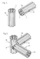
- Figur 1 eine perspektivische Teildarstellung eines erfindungsgemäß ausgestalteten Profilrohres mit achteckigem Außenquerschnitt,
- Figur 2 die schematische Darstellung der Ausbildung des hohlen Innenraumes des Profiles der Fig.1.
- Figur 3 die Explosionsdarstellung eines Profiles gemäß Fig. 1 mit einem stirnseitig in dieses Profilrohr einschiebbaren Spannglied,
- Figur 4 das Profil der Fig. 1 und 3 mit dem eingeschobenen Spannglied vor der Verbindung mit einem weiteren senkrechten Profilrohr mit der gleichen Ausbildung.
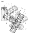
- Figur 5 drei erfindungsgemäß zusammengesetzte Profilrohre gemäß Fig. 1 und
- Figur 6 vier zusammengesetzte Profilrohre gemäß Fig. 1. wobei die wahlweise Anordnung des vierten Profilrohres in mehreren Lagen angedeutet ist.
- In der Fig. 1 ist ein Ausführungsbeispiel eines erfindungsgemäßen Profilrohres mit acht Ecken gezeigt, dessen acht Längsseiten 1 jeweils mit Längsnuten 2 versehen sind, die dadurch hinterschnitten sind, daß sie jeweils in Kammern 3 münden, die ebenfalls parallel zur Achse des Profilrohres verlaufen. In bekannter Weise und wie auch noch anhand von Fig.4 erläutert werden wird, können in die Längsnuten 2 Zugriegelspanner 5 von Spanngliedern 4 eingesetzt werden, die in den Längsnuten 2 dadurch verspannbar sind, daß sie nach dem Eingreifen in die Kammern 3 nach außen gespreizt und in Richtung zum Spannglied 4 zurückgezogen werden, was in bekannter Weise durch von außen betätigbare Schraubglieder 14 über nicht gezeigte Exzenter geschieht.
- Der hohle Innenraum 6 des achteckigen Profiles der Fig. 1 ist, wie näher aus Fig. 2 hervorgeht, mit mehreren nutförmigen Aussparungen 7a, 7b, 7c, 7d bzw. 8a, 8b, 8c, 8d und 9a bis 9d sowie 10a bis 10d versehen, die jeweils parallel zueinander und diametral gegenüber angeordnet sind. Dabei sind alle Aussparungen 7a, 7b, 7c, 7d - und auch die anderen Aussparungen - parallel zueinander angeordnet. Die Aussparungen (z. B. 9a und 9b), die jeweils eine dreieckigen und gleichschenkligen Querschnitt haben, bestimmen dabei durch ihren Abstand a zueinander und durch den Abstand b gegenüber den beiden zugeordneten, aber diametral gegenüberliegenden Aussparungen 9c und 9d den gestrichelt durch die Linie 11 und 12 und durch die jeweiligen Verbindungslinien der äußersten Ecken der Aussparungen 9a, 9b, 9d begrenzten, freien, rechteckigen Querschnitt, in der stirnseitig ein Spannglied 4 in das Profilrohr 13 einschiebbar ist. Dieser Querschnitt entspricht dem Querschnitt des Spanngliedes 4, wie aus Fig. erkennbar ist. Durch diese Ausgestaltung wird es möglich, das Spannglied 4 mit seinen rechteckigen Abmessungen jeweils in vier verschiedenen Winkellagen in das Profilrohr 13 stirnseitig einzusetzen, wenn das zur Betätigung der Zugriegelspanner 5 notwendige Schraubglied 14, das mit einem Exzenter verbunden sein kann, vorher entfernt ist.
- Fig.4 4 zeigt das stirnseitig eingeschobene Spannglied 4 mit den Zugriegelspannern 5, die in der dargestellten Lage so zusammengeschoben sind, daß sie sich durch die Längsnuten 2 einführen lassen. Durch die seitliche, in die Längsnuten 2 mündende Öffnung 15 kann nun das Schraubglied 14 mit dem Exzenter betätigt werden, der zwischen die Zugriegelspanner 5 greift, sie seitlich auseinanderdrückt und in Richtung zum Spannglied 4 zieht, so daß das Profilrohr 13a rechtwinklig mit dem Profilrohr 13b verbindbar ist.
- Fig. 5 zeigt drei untereinander verbundene Profilrohre 13a, 13b und 13c, die jeweils durch die stirnseitig eingeschobenen Spannglieder 4, die in Fig. 5 nicht erkennbar sind, rechtwinklig untereinander zusammengehalten sind. Aus optischen Gründen, aber auch um eine unnötige Verschmutzung oder ein unbeabsichtigtes Verklemmen von außen zugeführter Teile zu vermeiden, sind stirnseitig an den beiden Profilrohren 13b und 13c jeweils Anpassungsstücke 16 vorgesehen, die den bei achteckigen Profilen sonst bei einem stirnseitigen Anschluß zwangsläufig entstehenden Abstand überbrücken.
- Fig. 6 zeigt, daß durch Einsetzen eines weiteren Spanngliedes an der Stirnseite 13c' des Profilrohres 13c der Fig. 5 ein viertes Profilrohr 13d an das Profilrohr 13c angeschlossen werden kann, und zwar im Ausführungsbeispiel unter einem Winkel von 45° zu der Achse 17 des senkrecht stehenden Profilrohres 13a. Wie strichpunktiert, gestrichelt und punktiert angedeutet ist, lassen sich aber auch bei geeigneter Verdrehung des Spanngliedes im Profilrohr 13c die Lagen 13d', 13d", 13d'" erreichen, von denen die Lage 13 d' parallel zu dem Profilrohr 13b, die Lage 13d" parallel zu dem Profilrohr 13a und die Lage 13d'" um 90° versetzt zu der ausgezogenen Lage des Profilrohres 13d ist. Fig. 6 veranschaulicht damit die Fülle der Variationsmöglichkeiten des Zusammenbaus von Profilrohren 13a bis 13d. Es ist natürlich nach wie vor möglich, wie beim Stand der Technik, auch noch andere Profilteile, beispielsweise gebogene oder gerade rechteckige Trägerprofile mit oder ohne Längsnuten an den Profilrohren 13a bis 13d über Spannglieder 4 anzuschließen, wie das auch beim Stand der Technik möglich war. Die Winkelvariation von Profilrohren 13a bis 13d jedoch verbessert die Aufbaumöglichkeiten von Gestellen nach dem Stand der Technik.
Claims (3)
Priority Applications (1)
| Application Number | Priority Date | Filing Date | Title |
|---|---|---|---|
| AT84113921T ATE27019T1 (de) | 1983-11-25 | 1984-11-17 | Profilrohr fuer die herstellung von leicht montier- und wieder demontierbaren aufbauten. |
Applications Claiming Priority (2)
| Application Number | Priority Date | Filing Date | Title |
|---|---|---|---|
| DE19833342616 DE3342616A1 (de) | 1983-11-25 | 1983-11-25 | Profilrohr fuer die herstellung von leicht montier- und wieder demontierbaren aufbauten |
| DE3342616 | 1983-11-25 |
Publications (3)
| Publication Number | Publication Date |
|---|---|
| EP0144030A2 EP0144030A2 (de) | 1985-06-12 |
| EP0144030A3 EP0144030A3 (en) | 1985-08-21 |
| EP0144030B1 true EP0144030B1 (de) | 1987-05-06 |
Family
ID=6215220
Family Applications (1)
| Application Number | Title | Priority Date | Filing Date |
|---|---|---|---|
| EP84113921A Expired EP0144030B1 (de) | 1983-11-25 | 1984-11-17 | Profilrohr für die Herstellung von leicht montier- und wieder demontierbaren Aufbauten |
Country Status (6)
| Country | Link |
|---|---|
| US (1) | US4583359A (de) |
| EP (1) | EP0144030B1 (de) |
| AT (1) | ATE27019T1 (de) |
| CA (1) | CA1236678A (de) |
| DE (2) | DE3342616A1 (de) |
| ES (1) | ES282162Y (de) |
Cited By (2)
| Publication number | Priority date | Publication date | Assignee | Title |
|---|---|---|---|---|
| DE19834372C1 (de) * | 1998-07-30 | 1999-10-28 | Octanorm Vertriebsgesellschaft | Profilrohr für die Herstellung kurzzeitiger Aufbauten |
| DE102006059887A1 (de) | 2006-12-19 | 2008-07-03 | Bfe Studio Und Medien Systeme Gmbh | Profil für Profilsysteme |
Families Citing this family (54)
| Publication number | Priority date | Publication date | Assignee | Title |
|---|---|---|---|---|
| DE3541400A1 (de) * | 1985-11-22 | 1987-06-04 | Hering Pt Bau Produkt Technik | Tragwerk fuer die abstuetzung von bauelementen |
| FR2601982B1 (fr) * | 1986-07-25 | 1990-11-02 | Chailleux Georges | Barre pour la realisation d'une structure spatiale, et dispositif de fixation d'une telle barre a un noeud spherique |
| DE3636639A1 (de) * | 1986-10-28 | 1988-05-05 | Abr Bausystem Ag | Bauelement-system |
| FR2607559B1 (fr) * | 1986-12-01 | 1989-03-03 | Savale Yves | Systeme d'assemblage de panneaux en des positions angulaires variees, et panneaux adaptes a l'utilisation de ce systeme |
| DE3726503A1 (de) * | 1987-08-08 | 1989-02-23 | Schoenfeld Hans Victor | Bauelement |
| DE8901539U1 (de) * | 1989-02-10 | 1990-06-21 | Wolf - Montage - Automationsanlagen + Sondermaschinen - Gmbh, 8702 Helmstadt, De | |
| US5214899A (en) * | 1989-06-05 | 1993-06-01 | Beeche Gregory L | Modular truss frame system |
| US4974987A (en) * | 1989-07-06 | 1990-12-04 | Matrix Exhibits, Inc. | Locking devices for exhibit framework systems |
| DE3942120A1 (de) * | 1989-12-20 | 1991-06-27 | Kurt Gassler | Tragkonstruktion, insbesondere fuer leicht montier- und demontierbare messebauten |
| US5175971A (en) * | 1991-06-17 | 1993-01-05 | Mccombs P Roger | Utility power pole system |
| DE4132447C2 (de) * | 1991-09-28 | 1994-02-10 | Dellen Wilhelm Von Der Dipl Vo | Anordnung zur Erstellung von Wand- und/oder Deckenkonstruktionen, insbesondere im Messebau |
| US5277512A (en) * | 1992-03-16 | 1994-01-11 | Pdl Holdings Ltd. | Joint for detachable connection of structural members |
| US5816000A (en) * | 1992-11-24 | 1998-10-06 | Havelock Europa Plc | Partition system |
| ES2121645B1 (es) * | 1994-11-21 | 1999-06-16 | Munoz Carcedo Jose | Construccion metalica modular desmontable y versatil. |
| US5870877A (en) * | 1994-12-07 | 1999-02-16 | Turner; Daryl | Truss structure for a utility pole |
| JPH08159119A (ja) * | 1994-12-07 | 1996-06-18 | N I Shi Auto Tec Kk | 連結材 |
| US5657604A (en) * | 1995-11-27 | 1997-08-19 | Downing Displays, Inc. | Panel connector |
| DE19601065A1 (de) * | 1996-01-13 | 1997-07-17 | Ernst Koller | Skelettgebäude aus Profilstäben |
| TW329446B (en) | 1996-04-29 | 1998-04-11 | Syma Intercontinental Sa | Profiled beam and clamping profile for profiled beams |
| US6155017A (en) * | 1996-11-04 | 2000-12-05 | Powertrusion 2000 | Truss structure |
| US6052950A (en) * | 1997-01-10 | 2000-04-25 | Exhibit Group/Giltspur | Modular structure having an elevated load-bearing surface |
| US5924258A (en) * | 1997-07-25 | 1999-07-20 | Geometrica, Inc. | Transverse cladding support apparatus and method |
| DE19752474A1 (de) * | 1997-11-27 | 1999-06-02 | Modul International Exhibition | Profil für Messebauten und dergleichen |
| US6453635B1 (en) | 1998-07-15 | 2002-09-24 | Powertrusion International, Inc. | Composite utility poles and methods of manufacture |
| EP0976891B1 (de) | 1998-07-30 | 2004-10-13 | Octanorm-Vertriebs-Gmbh Für Bauelemente | Aufbausystem |
| DE19855928A1 (de) | 1998-12-04 | 2000-06-08 | Wolfgang Rixen | Verbindung zweier Profilstäbe |
| US20020124478A1 (en) * | 2001-03-06 | 2002-09-12 | Rush James C. | Post and beam furniture system |
| US7096637B2 (en) | 2001-08-23 | 2006-08-29 | Mcmillan John Charles | Display structure and system |
| DE10156220C1 (de) * | 2001-11-15 | 2003-05-08 | Domo Architektursysteme Logist | Profilträgersystem, insbesondere für den Messe- und Ausstellungsbau |
| FR2834020B1 (fr) * | 2001-12-21 | 2004-08-27 | Arfeo | Systeme de cloisonnement d'un espace |
| EP1321592A1 (de) * | 2001-12-21 | 2003-06-25 | Paolo Manzi | Modulare Struktur für ein tragendes Rahmenwerk mit Profilkörpern und selbsttragenden Platten und Herstellungsverfahren dafür |
| ITTO20020421A1 (it) * | 2002-05-17 | 2003-11-17 | Comau Spa | Attrezzatura utilizzabile da un robot industriale per l'afferramento di pezzi o gruppi in lavorazione od assemblaggio,con struttura modulare |
| CA2490104C (en) * | 2002-06-21 | 2010-10-12 | Skyline Displays, Inc. | Framework connection system |
| US7559176B2 (en) * | 2002-10-18 | 2009-07-14 | Polyone Corporation | Concrete fillable formwork wall |
| US8322115B2 (en) * | 2002-10-18 | 2012-12-04 | Polyone Corporation | Insert panel for concrete fillable formwork wall |
| US20040187426A1 (en) * | 2003-03-31 | 2004-09-30 | Michael Callahan | Structures and components thereof |
| US20050188902A1 (en) * | 2003-11-28 | 2005-09-01 | Savoie Troy S. | Display table with accessory pole |
| US20050144857A1 (en) * | 2003-12-19 | 2005-07-07 | Fernando Guerrero | Modular building system |
| ITBS20040144A1 (it) * | 2004-12-01 | 2005-03-01 | Gimatic Spa | Profilato multivalente per la composizione di telai, supporti, strutture portanti e simili |
| ITMI20050269A1 (it) * | 2005-02-22 | 2006-08-23 | Marca Clac Di Cattaneo Sergio | Struttura costruttiva per mobili |
| WO2007143983A2 (de) | 2006-06-15 | 2007-12-21 | Haticon Gmbh | Montagesystem insbesondere für solarmodule |
| CA2616623C (en) * | 2007-01-03 | 2012-04-03 | Skyline Displays, Inc. | Multi-configurable tubular display system |
| US8028846B2 (en) * | 2008-09-05 | 2011-10-04 | Target Brands, Inc. | Flexible shelving system |
| JP2012526210A (ja) * | 2009-10-16 | 2012-10-25 | 常州▲りん▼通展▲覧▼用品有限公司 | 接続用ロック具 |
| US8367918B2 (en) * | 2009-12-01 | 2013-02-05 | Antonio Reyes | TRSeries drum rack system-acoustic and/or electronic drum mounting rack with eight-sided piping and interlocking clamps |
| DE102011109848A1 (de) * | 2011-08-09 | 2013-02-14 | Airbus Operations Gmbh | Grundkörper, Gerüstsystem sowie Herstellungsverfahren für einen derartigen Grundkörper |
| BG66739B1 (bg) * | 2012-05-22 | 2018-09-28 | "Стоа" Оод | Строителен профил, строителен набор, строителен комплект и закрепваща система за вентилируеми фасади |
| EP2900883B1 (de) * | 2012-09-26 | 2019-09-04 | Edoo, Quai-de Azam | Korrosionsbeständiges bewehrungselement |
| US10344467B1 (en) * | 2014-08-12 | 2019-07-09 | Bryx Group LLC | Glide rail |
| CN107166160A (zh) * | 2017-07-24 | 2017-09-15 | 南京圣旗智能科技有限公司 | 多功能型材及型材组件 |
| US10206506B1 (en) * | 2018-07-09 | 2019-02-19 | Shenter Enterprise Co., Ltd. | Frame with connecting and positioning structure |
| IT201900000124A1 (it) * | 2019-01-07 | 2020-07-07 | Cerloj Ema | Dispositivo di connessione per profili estrusi |
| IT201900000127A1 (it) * | 2019-01-07 | 2020-07-07 | Cerloj Ema | Profilo estruso |
| US11629495B2 (en) * | 2020-09-18 | 2023-04-18 | Wei-Jan Lin | Modular framing structure design and a method of using the same |
Family Cites Families (13)
| Publication number | Priority date | Publication date | Assignee | Title |
|---|---|---|---|---|
| NL262775A (de) * | 1961-03-24 | |||
| CH442870A (de) * | 1966-01-24 | 1967-08-31 | Mueller Hermann | Profilschienen-Verbindung |
| DE1650975A1 (de) * | 1968-01-26 | 1970-10-22 | Johannes Jankowski | Vorrichtung zum Anschliessen bzw. Verbinden von Bauelementen |
| BE767043A (fr) * | 1971-05-12 | 1971-10-01 | Janssen Leopold M L | Cloison double paroi et elements de cloison. |
| JPS5091914A (de) * | 1973-12-19 | 1975-07-23 | ||
| ZA754113B (en) * | 1974-06-27 | 1976-06-30 | Staeger Hans | Profile part for assembling mobile superstructures and installations |
| CH588233A5 (de) * | 1974-12-09 | 1977-05-31 | Syma Intercontinental Sa | |
| DE2616440C3 (de) * | 1976-04-14 | 1979-11-08 | Albrecht 7000 Stuttgart Streib | Lösbare Verbindung zweier Teile eines Gestells |
| AU514900B2 (en) * | 1976-12-07 | 1981-03-05 | Californian Nominees Pty. Ltd. | Framing system |
| US4142343A (en) * | 1977-09-20 | 1979-03-06 | Trafton Ronald H | Post apparatus and methods of constructing and utilizing same |
| DE2941008C2 (de) * | 1979-10-10 | 1981-09-10 | Gebrüder Vieler GmbH, 5860 Iserlohn | Gestell |
| DE3128595C2 (de) * | 1981-07-20 | 1990-12-06 | Gebrüder Vieler GmbH, 5860 Iserlohn | Gestell aus lösbar verbindbaren Profilstangen |
| CA1130359A (en) * | 1981-07-29 | 1982-08-24 | Jacques Ducharme | Dismantling joint for modular frame construction |
-
1983
- 1983-11-25 DE DE19833342616 patent/DE3342616A1/de not_active Withdrawn
-
1984
- 1984-10-22 ES ES1984282162U patent/ES282162Y/es not_active Expired
- 1984-10-31 CA CA000466680A patent/CA1236678A/en not_active Expired
- 1984-11-17 DE DE8484113921T patent/DE3463538D1/de not_active Expired
- 1984-11-17 AT AT84113921T patent/ATE27019T1/de not_active IP Right Cessation
- 1984-11-17 EP EP84113921A patent/EP0144030B1/de not_active Expired
- 1984-11-23 US US06/674,123 patent/US4583359A/en not_active Expired - Lifetime
Cited By (2)
| Publication number | Priority date | Publication date | Assignee | Title |
|---|---|---|---|---|
| DE19834372C1 (de) * | 1998-07-30 | 1999-10-28 | Octanorm Vertriebsgesellschaft | Profilrohr für die Herstellung kurzzeitiger Aufbauten |
| DE102006059887A1 (de) | 2006-12-19 | 2008-07-03 | Bfe Studio Und Medien Systeme Gmbh | Profil für Profilsysteme |
Also Published As
| Publication number | Publication date |
|---|---|
| DE3463538D1 (en) | 1987-06-11 |
| EP0144030A2 (de) | 1985-06-12 |
| DE3342616A1 (de) | 1985-06-05 |
| ES282162Y (es) | 1985-11-16 |
| EP0144030A3 (en) | 1985-08-21 |
| US4583359A (en) | 1986-04-22 |
| ATE27019T1 (de) | 1987-05-15 |
| CA1236678A (en) | 1988-05-17 |
| ES282162U (es) | 1985-04-16 |
Similar Documents
| Publication | Publication Date | Title |
|---|---|---|
| EP0144030B1 (de) | Profilrohr für die Herstellung von leicht montier- und wieder demontierbaren Aufbauten | |
| EP0297033A2 (de) | Verbindungselement für eine Stange | |
| DE3303190C2 (de) | Bausatz zur Erstellung mobiler Bauten, insbesondere für Messe- und Ausstellungsbauten | |
| DE1750969B1 (de) | Verbindungsvorrichtung zur verbindung rohrfoermiger teile | |
| DE10156220C1 (de) | Profilträgersystem, insbesondere für den Messe- und Ausstellungsbau | |
| DE3045266A1 (en) | Improvements in clamp members | |
| DE202017107404U1 (de) | Knotenverbinder für Profilsysteme oder dergleichen | |
| EP0325985A1 (de) | Unterdecke mit einem abgehängten Traggerippe | |
| DE3636639A1 (de) | Bauelement-system | |
| EP2392742A2 (de) | Kantenprofilelement | |
| EP0973985B1 (de) | Gitterträger zur herstellung mobiler bauten | |
| EP0399371B1 (de) | Verbindungsbeschlag für Stabelemente | |
| DE2832087A1 (de) | Verbindung von hohlprofilen, insbesondere zum aufbau von regalen, geruesten u.dgl. | |
| EP3242981B1 (de) | Schnellbauwand | |
| EP1995473A2 (de) | Verbindungselement und Gestellsystem | |
| EP0038086A2 (de) | Bausatz zur Herstellung von Gestellen, Möbeln, Regalen, transportablen Bauwerken und aus diesem Bausatz hergestellter Gegenstand | |
| WO1993017192A1 (de) | Konstruktionssystem | |
| DE3837505A1 (de) | Praesentationsgestell | |
| DE3617445C2 (de) | ||
| DE19513623A1 (de) | Hohlprofil-Metallgerüst | |
| DE3706236C2 (de) | Verbindungselement für zwei Tragteile | |
| DE19834372C1 (de) | Profilrohr für die Herstellung kurzzeitiger Aufbauten | |
| EP0876788A2 (de) | Mit einem Wandhalter versehenes, im Querschnitt U-förmiges Halteprofil für eine Trennwand | |
| DE3328232C2 (de) | Raumfachwerk | |
| AT400390B (de) | Profilleistensystem |
Legal Events
| Date | Code | Title | Description |
|---|---|---|---|
| PUAI | Public reference made under article 153(3) epc to a published international application that has entered the european phase |
Free format text: ORIGINAL CODE: 0009012 |
|
| AK | Designated contracting states |
Designated state(s): AT BE CH DE FR GB IT LI LU NL SE |
|
| PUAL | Search report despatched |
Free format text: ORIGINAL CODE: 0009013 |
|
| RTI1 | Title (correction) | ||
| RHK1 | Main classification (correction) |
Ipc: E04B 1/58 |
|
| RTI1 | Title (correction) | ||
| AK | Designated contracting states |
Designated state(s): AT BE CH DE FR GB IT LI LU NL SE |
|
| 17P | Request for examination filed |
Effective date: 19851002 |
|
| 17Q | First examination report despatched |
Effective date: 19860415 |
|
| GRAA | (expected) grant |
Free format text: ORIGINAL CODE: 0009210 |
|
| AK | Designated contracting states |
Kind code of ref document: B1 Designated state(s): AT BE CH DE FR GB IT LI LU NL SE |
|
| REF | Corresponds to: |
Ref document number: 27019 Country of ref document: AT Date of ref document: 19870515 Kind code of ref document: T |
|
| ITF | It: translation for a ep patent filed |
Owner name: JACOBACCI & PERANI S.P.A. |
|
| REF | Corresponds to: |
Ref document number: 3463538 Country of ref document: DE Date of ref document: 19870611 |
|
| ET | Fr: translation filed | ||
| PLBE | No opposition filed within time limit |
Free format text: ORIGINAL CODE: 0009261 |
|
| STAA | Information on the status of an ep patent application or granted ep patent |
Free format text: STATUS: NO OPPOSITION FILED WITHIN TIME LIMIT |
|
| 26N | No opposition filed | ||
| ITTA | It: last paid annual fee | ||
| EPTA | Lu: last paid annual fee | ||
| EAL | Se: european patent in force in sweden |
Ref document number: 84113921.5 |
|
| REG | Reference to a national code |
Ref country code: GB Ref legal event code: IF02 |
|
| PGFP | Annual fee paid to national office [announced via postgrant information from national office to epo] |
Ref country code: GB Payment date: 20021112 Year of fee payment: 19 |
|
| PGFP | Annual fee paid to national office [announced via postgrant information from national office to epo] |
Ref country code: DE Payment date: 20021113 Year of fee payment: 19 |
|
| PGFP | Annual fee paid to national office [announced via postgrant information from national office to epo] |
Ref country code: FR Payment date: 20021118 Year of fee payment: 19 |
|
| PGFP | Annual fee paid to national office [announced via postgrant information from national office to epo] |
Ref country code: AT Payment date: 20021119 Year of fee payment: 19 |
|
| PGFP | Annual fee paid to national office [announced via postgrant information from national office to epo] |
Ref country code: SE Payment date: 20021122 Year of fee payment: 19 Ref country code: CH Payment date: 20021122 Year of fee payment: 19 Ref country code: BE Payment date: 20021122 Year of fee payment: 19 |
|
| PGFP | Annual fee paid to national office [announced via postgrant information from national office to epo] |
Ref country code: LU Payment date: 20021125 Year of fee payment: 19 |
|
| PG25 | Lapsed in a contracting state [announced via postgrant information from national office to epo] |
Ref country code: LU Free format text: LAPSE BECAUSE OF NON-PAYMENT OF DUE FEES Effective date: 20031117 Ref country code: GB Free format text: LAPSE BECAUSE OF NON-PAYMENT OF DUE FEES Effective date: 20031117 Ref country code: AT Free format text: LAPSE BECAUSE OF NON-PAYMENT OF DUE FEES Effective date: 20031117 |
|
| PGFP | Annual fee paid to national office [announced via postgrant information from national office to epo] |
Ref country code: NL Payment date: 20031117 Year of fee payment: 20 |
|
| PG25 | Lapsed in a contracting state [announced via postgrant information from national office to epo] |
Ref country code: SE Free format text: LAPSE BECAUSE OF NON-PAYMENT OF DUE FEES Effective date: 20031118 |
|
| PG25 | Lapsed in a contracting state [announced via postgrant information from national office to epo] |
Ref country code: LI Free format text: LAPSE BECAUSE OF NON-PAYMENT OF DUE FEES Effective date: 20031130 Ref country code: CH Free format text: LAPSE BECAUSE OF NON-PAYMENT OF DUE FEES Effective date: 20031130 Ref country code: BE Free format text: LAPSE BECAUSE OF NON-PAYMENT OF DUE FEES Effective date: 20031130 |
|
| BERE | Be: lapsed |
Owner name: *OCTANORM-VERTRIEBS-G.M.B.H. Effective date: 20031130 |
|
| PG25 | Lapsed in a contracting state [announced via postgrant information from national office to epo] |
Ref country code: DE Free format text: LAPSE BECAUSE OF NON-PAYMENT OF DUE FEES Effective date: 20040602 |
|
| EUG | Se: european patent has lapsed | ||
| GBPC | Gb: european patent ceased through non-payment of renewal fee |
Effective date: 20031117 |
|
| REG | Reference to a national code |
Ref country code: CH Ref legal event code: PL |
|
| PG25 | Lapsed in a contracting state [announced via postgrant information from national office to epo] |
Ref country code: FR Free format text: LAPSE BECAUSE OF NON-PAYMENT OF DUE FEES Effective date: 20040730 |
|
| REG | Reference to a national code |
Ref country code: FR Ref legal event code: ST |
|
| PG25 | Lapsed in a contracting state [announced via postgrant information from national office to epo] |
Ref country code: NL Free format text: LAPSE BECAUSE OF EXPIRATION OF PROTECTION Effective date: 20041117 |
|
| NLV7 | Nl: ceased due to reaching the maximum lifetime of a patent |
Effective date: 20041117 |