EP0141983A2 - Armature de poignée - Google Patents
Armature de poignée Download PDFInfo
- Publication number
- EP0141983A2 EP0141983A2 EP84111404A EP84111404A EP0141983A2 EP 0141983 A2 EP0141983 A2 EP 0141983A2 EP 84111404 A EP84111404 A EP 84111404A EP 84111404 A EP84111404 A EP 84111404A EP 0141983 A2 EP0141983 A2 EP 0141983A2
- Authority
- EP
- European Patent Office
- Prior art keywords
- handle
- screw
- plate
- cover plate
- collar
- Prior art date
- Legal status (The legal status is an assumption and is not a legal conclusion. Google has not performed a legal analysis and makes no representation as to the accuracy of the status listed.)
- Granted
Links
Images

Classifications
-
- E—FIXED CONSTRUCTIONS
- E05—LOCKS; KEYS; WINDOW OR DOOR FITTINGS; SAFES
- E05B—LOCKS; ACCESSORIES THEREFOR; HANDCUFFS
- E05B9/00—Lock casings or latch-mechanism casings ; Fastening locks or fasteners or parts thereof to the wing
- E05B9/08—Fastening locks or fasteners or parts thereof, e.g. the casings of latch-bolt locks or cylinder locks to the wing
- E05B9/082—Fastening locks or fasteners or parts thereof, e.g. the casings of latch-bolt locks or cylinder locks to the wing with concealed screws
Definitions
- the invention relates to a handle fitting, in particular for espagnolette locks on windows or the like, with a screw-on plate supporting the handle handle, the screw holes of which are covered by a cover plate which is clip-fastened in the region of a collar near the bearing bush of the handle handle.
- the cover plate forms a cap in connection with an angled peripheral edge, which covers the entire screw-on plate.
- the production of such cover plates requires a higher material requirement and complex tool shapes.
- the object of the invention is based on the task of equipping a handle fitting of the required type with a technically simple cover plate which can be stably anchored with easy assembly.
- the cover plate is inserted with a recess that is open on one side under the collar and is held with noses on the underside of the collar that are latched into holes in the cover plate and is folded on its opposite side to form an angle profile, the narrow edges of the angled leg take hold of shoulders on the side flanks of the mounting plate.
- a generic handle fitting is specified, which is characterized in particular by a constructionally simple and material-saving construction.
- the cover plate can be mounted very easily. This can even happen if the handle is already attached.
- the cover plate is mounted by means of the plug connection.
- the holes in the cover plate engage with the lugs on the underside of the collar, while the narrow edges of the angled leg engage behind the shoulders of the side flanks of the screw-on plate.
- the cover plate held in this way withstands the wear and tear. You can only will. be stressed out of their position.
- the cover plate is adequately fixed in that the storage recess extends only over half the thickness of the screw-on plate. It is possible to design the screw-on plate and the cover plate in different colors.
- both legs of the cover plate are sunk in a storage recess. The latter therefore extends at an angle on the corresponding walls of the screw-on plate.
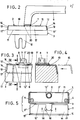
- the handle fitting 2 assigned to a window sash 1 has a screw-on plate 3 which is rectangular in plan. This is equipped with screw holes 4 in the area of its narrow edges. The latter are penetrated by fastening screws 5 which engage in the window sash 1.
- a bearing bush 6 embedded in the screw-on plate 6.
- the latter is arranged offset in the transverse central plane in such a way that it extends near one longitudinal edge 3 'of the screw-on plate 3.
- the bearing bush 6 ends with a rectangular collar 7.
- the underside of the collar 7 'lies approximately at the level of the surface of the screw-on plate 3.
- a bearing mandrel 8 is rotatably fixed in the bearing bush 6.
- Whose square section carries a handle handle 9. The position of the handle handle shown in full lines in Fig. 1 corresponds to the closed position. If the handle is swiveled 90 ° counterclockwise, the open position is reached.
- the gap ventilation position is reached by further swiveling the handle handle into the position also indicated by dash-dotted lines.
- a drive rod actuating slide 10 is displaced via a gear, not shown, accommodated in the screw-on plate.
- a flat storage recess 11 extends from the top of the screw-on plate 3 and continues into the longitudinal edge 3 ′′. There, the storage recess extends' only about half the thickness of the screw-on plate, cf. in particular FIG. 4.
- the storage recess 11 runs the top of the screw-on plate in such a way that there remains an edge-side web 12. This frames the bearing bush 6 to form an oval web 12 '. Since the storage recess also extends over the longitudinal edge 3 ", there shoulders 14 on the side flanks 13, which in the go over the edge-side web 12.
- the side flanks 13 run at the level of the storage recess 11 inclined in the direction of the handle. The shoulders 13 are arranged parallel to the inclined course of the side flanks.
- the longitudinal edge 3 "extends at the level of the recess inclined in the direction of the bearing bush 6 with an obtuse angle. Between the top of the screw-on plate and the adjacent longitudinal edge 3".
- cover plate 15 After fastening the screw-on plate 3 by means of the fastening screws 5, these can be overlaid by a cover plate 15.
- the latter is designed as an angle profile, consisting of a longer angle leg 16 and a shorter angle leg 17. The angle enclosed by these two corresponds to the angle between the top of the screw-on plate and the longitudinal edge 3 ".
- a recess 18 extends from one side 16 'of the angled leg 16.
- the latter is adapted to the contour of the oval web 12 '.
- the angle leg 16 corresponds in the outline of the recess 11 in the area of the top of the screw-on plate 3.
- the recess 18 is adjacent to two holes 19 which are at the level of lugs 20 on the underside 7 'of the collar 7 of the bearing bush 6.
- the shorter angle leg 17 corresponds in its contour to the recess 11 in the region of the longitudinal edge 3 ".
- the fixing of the cover plate can be seen in particular in FIGS. 4 and 5.
- the cover plate 15 is, as indicated by dash-dotted lines in FIG. 4, inserted with its longer angle leg 16 first into the recess 11 at the level of the screw-on plate top.
- the recess 18 includes the oval web 12 'of the screw-on plate, and in the final phase of the insertion movement the lugs 20 engage in the holes 19 of the angle leg 16, while the shorter angle leg 17 with its narrow edges 17' fits behind the shoulders 14 of the screw-on plate .
- the cover plate 15 cannot be removed upwards, since it is supported on the one hand on the underside of the collar 7 and on the other hand, with its shorter angle leg 17, is located behind the shoulders 14.
- the cover plate can only be removed after the latching has been released, so that this presupposes voluntary handling.
- the collar 7 of the bearing bush 6 is of such a size that it covers both the recess 18 and the holes 19 completely when the cover plate 15 is attached.
Landscapes
- Engineering & Computer Science (AREA)
- Mechanical Engineering (AREA)
- Connection Of Plates (AREA)
- Lock And Its Accessories (AREA)
- Saccharide Compounds (AREA)
- Measurement Of The Respiration, Hearing Ability, Form, And Blood Characteristics Of Living Organisms (AREA)
- Steering Devices For Bicycles And Motorcycles (AREA)
- Casings For Electric Apparatus (AREA)
- Details Of Measuring And Other Instruments (AREA)
Priority Applications (1)
| Application Number | Priority Date | Filing Date | Title |
|---|---|---|---|
| AT84111404T ATE32620T1 (de) | 1983-11-04 | 1984-09-25 | Griffbeschlag. |
Applications Claiming Priority (2)
| Application Number | Priority Date | Filing Date | Title |
|---|---|---|---|
| DE8331639U | 1983-11-04 | ||
| DE19838331639U DE8331639U1 (de) | 1983-11-04 | 1983-11-04 | Griffbeschlag |
Publications (3)
| Publication Number | Publication Date |
|---|---|
| EP0141983A2 true EP0141983A2 (fr) | 1985-05-22 |
| EP0141983A3 EP0141983A3 (en) | 1986-01-15 |
| EP0141983B1 EP0141983B1 (fr) | 1988-02-24 |
Family
ID=6758583
Family Applications (1)
| Application Number | Title | Priority Date | Filing Date |
|---|---|---|---|
| EP84111404A Expired EP0141983B1 (fr) | 1983-11-04 | 1984-09-25 | Armature de poignée |
Country Status (3)
| Country | Link |
|---|---|
| EP (1) | EP0141983B1 (fr) |
| AT (1) | ATE32620T1 (fr) |
| DE (2) | DE8331639U1 (fr) |
Family Cites Families (3)
| Publication number | Priority date | Publication date | Assignee | Title |
|---|---|---|---|---|
| DE2016844A1 (de) * | 1970-04-09 | 1971-10-21 | Fa Wüh Engstfeld, 5 628 Heih genhaus | Beschlag fur Fenster, Türen oder dergleichen |
| DE2215968A1 (de) * | 1972-04-01 | 1973-10-04 | Engstfeld Wilh Fa | Beschlag fuer fenster, tueren od. dgl. |
| DE3132856C2 (de) * | 1981-08-20 | 1987-03-19 | HEWI Heinrich Wilke GmbH, 3548 Arolsen | Rosette |
-
1983
- 1983-11-04 DE DE19838331639U patent/DE8331639U1/de not_active Expired
-
1984
- 1984-09-25 AT AT84111404T patent/ATE32620T1/de not_active IP Right Cessation
- 1984-09-25 DE DE8484111404T patent/DE3469453D1/de not_active Expired
- 1984-09-25 EP EP84111404A patent/EP0141983B1/fr not_active Expired
Also Published As
| Publication number | Publication date |
|---|---|
| EP0141983A3 (en) | 1986-01-15 |
| EP0141983B1 (fr) | 1988-02-24 |
| DE3469453D1 (en) | 1988-03-31 |
| ATE32620T1 (de) | 1988-03-15 |
| DE8331639U1 (de) | 1985-04-18 |
Similar Documents
| Publication | Publication Date | Title |
|---|---|---|
| DE2834342C2 (de) | Lager für Wendeflügelfenster | |
| DE2541554B2 (de) | Beschlaganordnung für Kastenmöbel | |
| DE2611323A1 (de) | Einstellvorrichtung | |
| DE2234677A1 (de) | Beschlag zum verbinden relativ zueinander bewegbar verstellbarer bauteile | |
| EP0141983B1 (fr) | Armature de poignée | |
| DE2449352C2 (de) | Stulpabdecksschiene für einen Treibstangenbeschlag, insbesondere Drehkipp-Beschlag für Fenster, Türen oder dergleichen | |
| CH617981A5 (en) | Housing for a locking device | |
| DE2149503C3 (de) | Möbelscharnier | |
| DE2645671C2 (de) | Aus einzelnen Torfelder gebildetes Deckengliedertor | |
| DE2403078C2 (de) | Behälter für Massengüter | |
| EP1080515B1 (fr) | Systeme de fermeture a barres muni d'un dispositif de mise a la terre | |
| DE2605959C3 (de) | Türbefestigung an einem Kabelverteilerschrank aus Kunststoff | |
| DE2229348A1 (de) | Verbergbares Scharnierteil, insbesondere für Möbel | |
| CH407189A (de) | Kühlschrank | |
| AT253729B (de) | Einrichtung zur Verkleidung der zwischen Schrank und Zimmerdecke sich ergebenden freien Räume | |
| DE29604643U1 (de) | Schaltschrank mit Rahmengestell und Tür mit Schubstangenverschluß | |
| DE672317C (de) | Mit einem ausziehbaren Fachboden gekuppelte, um eine zur Fachbodenvorderkante parallele Achse schwenkbare Verschlussklappe fuer Moebel | |
| DE1708341C3 (de) | Ausstellvorrichtung für einen Dreh-Kipp-Beschlag eines Fensters, einer Tür o.dgl | |
| DE2320957C3 (de) | Schnappverschluß für Gehäuseabdeckungen | |
| EP0442168B1 (fr) | Disposition de la charnière d'une porte d'armoire de distribution | |
| DE2756487C3 (de) | Fenster | |
| AT397121B (de) | Möbelscharnier | |
| DE9215622U1 (de) | Schloßkastenantrieb für eine Mehrfach-Verriegelung | |
| CH624355A5 (en) | Handle for containers or boxes | |
| DE7237740U (de) | Feststellbeschlag für Klappen von Möbeln |
Legal Events
| Date | Code | Title | Description |
|---|---|---|---|
| PUAI | Public reference made under article 153(3) epc to a published international application that has entered the european phase |
Free format text: ORIGINAL CODE: 0009012 |
|
| AK | Designated contracting states |
Designated state(s): AT BE CH DE FR GB IT LI LU NL SE |
|
| PUAL | Search report despatched |
Free format text: ORIGINAL CODE: 0009013 |
|
| AK | Designated contracting states |
Designated state(s): AT BE CH DE FR GB IT LI LU NL SE |
|
| 17P | Request for examination filed |
Effective date: 19851213 |
|
| 17Q | First examination report despatched |
Effective date: 19870721 |
|
| GRAA | (expected) grant |
Free format text: ORIGINAL CODE: 0009210 |
|
| AK | Designated contracting states |
Kind code of ref document: B1 Designated state(s): AT BE CH DE FR GB IT LI LU NL SE |
|
| REF | Corresponds to: |
Ref document number: 32620 Country of ref document: AT Date of ref document: 19880315 Kind code of ref document: T |
|
| GBT | Gb: translation of ep patent filed (gb section 77(6)(a)/1977) | ||
| REF | Corresponds to: |
Ref document number: 3469453 Country of ref document: DE Date of ref document: 19880331 |
|
| ET | Fr: translation filed | ||
| ITF | It: translation for a ep patent filed | ||
| PG25 | Lapsed in a contracting state [announced via postgrant information from national office to epo] |
Ref country code: LU Free format text: LAPSE BECAUSE OF NON-PAYMENT OF DUE FEES Effective date: 19880930 |
|
| PLBE | No opposition filed within time limit |
Free format text: ORIGINAL CODE: 0009261 |
|
| STAA | Information on the status of an ep patent application or granted ep patent |
Free format text: STATUS: NO OPPOSITION FILED WITHIN TIME LIMIT |
|
| 26N | No opposition filed | ||
| PGFP | Annual fee paid to national office [announced via postgrant information from national office to epo] |
Ref country code: SE Payment date: 19890626 Year of fee payment: 6 Ref country code: FR Payment date: 19890626 Year of fee payment: 6 |
|
| PGFP | Annual fee paid to national office [announced via postgrant information from national office to epo] |
Ref country code: LU Payment date: 19890628 Year of fee payment: 6 |
|
| PGFP | Annual fee paid to national office [announced via postgrant information from national office to epo] |
Ref country code: BE Payment date: 19890710 Year of fee payment: 6 |
|
| PGFP | Annual fee paid to national office [announced via postgrant information from national office to epo] |
Ref country code: AT Payment date: 19890904 Year of fee payment: 6 |
|
| ITTA | It: last paid annual fee | ||
| PGFP | Annual fee paid to national office [announced via postgrant information from national office to epo] |
Ref country code: NL Payment date: 19890930 Year of fee payment: 6 |
|
| PGFP | Annual fee paid to national office [announced via postgrant information from national office to epo] |
Ref country code: CH Payment date: 19891108 Year of fee payment: 6 |
|
| PG25 | Lapsed in a contracting state [announced via postgrant information from national office to epo] |
Ref country code: AT Effective date: 19900925 |
|
| PG25 | Lapsed in a contracting state [announced via postgrant information from national office to epo] |
Ref country code: SE Effective date: 19900926 |
|
| PG25 | Lapsed in a contracting state [announced via postgrant information from national office to epo] |
Ref country code: LI Effective date: 19900930 Ref country code: CH Effective date: 19900930 Ref country code: BE Effective date: 19900930 |
|
| BERE | Be: lapsed |
Owner name: CARL FUHR G.M.B.H. & CO. Effective date: 19900930 |
|
| PG25 | Lapsed in a contracting state [announced via postgrant information from national office to epo] |
Ref country code: NL Effective date: 19910401 |
|
| NLV4 | Nl: lapsed or anulled due to non-payment of the annual fee | ||
| PG25 | Lapsed in a contracting state [announced via postgrant information from national office to epo] |
Ref country code: FR Effective date: 19910530 |
|
| REG | Reference to a national code |
Ref country code: CH Ref legal event code: PL |
|
| REG | Reference to a national code |
Ref country code: FR Ref legal event code: ST |
|
| PGFP | Annual fee paid to national office [announced via postgrant information from national office to epo] |
Ref country code: GB Payment date: 19910806 Year of fee payment: 8 |
|
| PGFP | Annual fee paid to national office [announced via postgrant information from national office to epo] |
Ref country code: DE Payment date: 19910905 Year of fee payment: 8 |
|
| PG25 | Lapsed in a contracting state [announced via postgrant information from national office to epo] |
Ref country code: GB Effective date: 19920925 |
|
| GBPC | Gb: european patent ceased through non-payment of renewal fee |
Effective date: 19920925 |
|
| PG25 | Lapsed in a contracting state [announced via postgrant information from national office to epo] |
Ref country code: DE Effective date: 19930602 |
|
| EUG | Se: european patent has lapsed |
Ref document number: 84111404.4 Effective date: 19910527 |