EP0141334B1 - Transporteinrichtung nach Art einer Förderbandeinrichtung - Google Patents
Transporteinrichtung nach Art einer Förderbandeinrichtung Download PDFInfo
- Publication number
- EP0141334B1 EP0141334B1 EP84112458A EP84112458A EP0141334B1 EP 0141334 B1 EP0141334 B1 EP 0141334B1 EP 84112458 A EP84112458 A EP 84112458A EP 84112458 A EP84112458 A EP 84112458A EP 0141334 B1 EP0141334 B1 EP 0141334B1
- Authority
- EP
- European Patent Office
- Prior art keywords
- transporting
- transport path
- conveyor belt
- transporting belt
- travelling
- Prior art date
- Legal status (The legal status is an assumption and is not a legal conclusion. Google has not performed a legal analysis and makes no representation as to the accuracy of the status listed.)
- Expired
Links
- 238000009434 installation Methods 0.000 title 1
- 238000005096 rolling process Methods 0.000 claims abstract description 25
- 230000001360 synchronised effect Effects 0.000 claims description 9
- 230000008859 change Effects 0.000 claims description 6
- 238000006073 displacement reaction Methods 0.000 claims 1
- 230000015654 memory Effects 0.000 description 6
- 239000000523 sample Substances 0.000 description 4
- 230000001133 acceleration Effects 0.000 description 3
- 238000010276 construction Methods 0.000 description 3
- 230000000694 effects Effects 0.000 description 3
- 230000009467 reduction Effects 0.000 description 3
- 230000005540 biological transmission Effects 0.000 description 2
- 239000004020 conductor Substances 0.000 description 2
- 230000001419 dependent effect Effects 0.000 description 2
- 238000011161 development Methods 0.000 description 2
- 230000018109 developmental process Effects 0.000 description 2
- 238000010586 diagram Methods 0.000 description 2
- 230000005484 gravity Effects 0.000 description 2
- 102100027237 MAM domain-containing protein 2 Human genes 0.000 description 1
- 101710116166 MAM domain-containing protein 2 Proteins 0.000 description 1
- 238000010521 absorption reaction Methods 0.000 description 1
- 230000006978 adaptation Effects 0.000 description 1
- 230000006399 behavior Effects 0.000 description 1
- 238000005452 bending Methods 0.000 description 1
- 230000006835 compression Effects 0.000 description 1
- 238000007906 compression Methods 0.000 description 1
- 238000005265 energy consumption Methods 0.000 description 1
- 238000005516 engineering process Methods 0.000 description 1
- 230000006870 function Effects 0.000 description 1
- 230000003993 interaction Effects 0.000 description 1
- 238000005339 levitation Methods 0.000 description 1
- 238000012423 maintenance Methods 0.000 description 1
- 238000004519 manufacturing process Methods 0.000 description 1
- 238000000034 method Methods 0.000 description 1
- 239000004033 plastic Substances 0.000 description 1
- 230000008569 process Effects 0.000 description 1
- 230000001141 propulsive effect Effects 0.000 description 1
- 238000007665 sagging Methods 0.000 description 1
- 238000005507 spraying Methods 0.000 description 1
- 239000000725 suspension Substances 0.000 description 1
- 230000007704 transition Effects 0.000 description 1
- XLYOFNOQVPJJNP-UHFFFAOYSA-N water Substances O XLYOFNOQVPJJNP-UHFFFAOYSA-N 0.000 description 1
- 238000004804 winding Methods 0.000 description 1
Images


Classifications
-
- B—PERFORMING OPERATIONS; TRANSPORTING
- B65—CONVEYING; PACKING; STORING; HANDLING THIN OR FILAMENTARY MATERIAL
- B65G—TRANSPORT OR STORAGE DEVICES, e.g. CONVEYORS FOR LOADING OR TIPPING, SHOP CONVEYOR SYSTEMS OR PNEUMATIC TUBE CONVEYORS
- B65G23/00—Driving gear for endless conveyors; Belt- or chain-tensioning arrangements
- B65G23/22—Arrangements or mountings of driving motors
- B65G23/23—Arrangements or mountings of driving motors of electric linear motors
-
- B—PERFORMING OPERATIONS; TRANSPORTING
- B65—CONVEYING; PACKING; STORING; HANDLING THIN OR FILAMENTARY MATERIAL
- B65G—TRANSPORT OR STORAGE DEVICES, e.g. CONVEYORS FOR LOADING OR TIPPING, SHOP CONVEYOR SYSTEMS OR PNEUMATIC TUBE CONVEYORS
- B65G54/00—Non-mechanical conveyors not otherwise provided for
- B65G54/02—Non-mechanical conveyors not otherwise provided for electrostatic, electric, or magnetic
Definitions
- the invention relates to a transport device according to the preamble of claim 1 or claim 6.
- Such a transport device is known from DE-B-1 183 011.
- the conveyor belt sections which have a pear-shaped cross-section when loaded and can be opened like a zip for unloading, hang freely on central trolleys, of which at least one is provided with a rotary, conventional electric motor as the drive device for each conveyor belt section.
- the invention creates a transport device, which is designed according to the characterizing part of claim 1, and a transport device, which is designed according to the characterizing part of claim 6.
- the transport device is characterized by a simple structure, decentralized introduction of the drive power and at least partial relief of the conveyor belt from longitudinal drive forces.
- the transport belt is driven by a suitably designed, electric linear motor which brings the drive power into the transport belt distributed over a length in the transport path longitudinal direction.
- the rolling bodies can be relieved at least in part, preferably largely or even almost completely or completely, of the absorption of load-bearing capacities which result from the weight of the conveyor belt or from the goods to be transported; Rather, they primarily serve to maintain the air gap distance of the linear motor.
- the weight of the conveyor belt and the goods to be transported can be borne at least partially, preferably predominantly or even almost completely or completely, by the permanent magnets attracting to the traveling field stator.
- the traveling field stator and the permanent magnets arranged in a row form a device that, in combination, provides both load and propelling forces.
- the conveyor belt can be located below the arrangement of the traveling field stator and permanent magnet or also above this arrangement, examples of which are given below.
- the air gap distance of the linear motor does not have to be constant, but can be variable along the transport device and / or depending on the loading condition of the conveyor belt, examples of which are given below.
- the rolling elements functionally form part of the linear motor and move along with the conveyor belt along the transport path.
- the conveyor belt is not deformed during its movement in the longitudinal direction of the transport path, as is the case with conventional conveyor belt devices, when rolling bodies roll over it.
- the cross-sectional shape of the conveyor belt is essentially preserved, and deformation work in the conveyor belt and the internal friction induced thereby in the goods to be transported are avoided. This results in lower energy consumption.
- the cross-sectional shape of the conveyor belt can be selected without taking into account the direct support of the rolling elements, preferably strongly trough-shaped to increase the transport capacity, which also reduces the effects of wind or the like on the goods to be transported.
- the linear motors can be provided with a load-bearing direction in such a way that the load-bearing direction at the edge of the conveyor belt with its orientation is completely or almost completely, in particular when the conveyor belt in cross-section has an upwardly concave, trough-shaped shape coincides. This can result in configurations in which the direction of load of the two linear motors points obliquely upwards from the center of the conveyor belt.
- the carrying elements for the conveyor belt for unloading the conveyor belt are preferably pivotable in whole or in part.
- the conveyor belt can be unloaded particularly inexpensively in an unloading area, without having to drive constructive effort on the actual linear motor.
- a particularly simple, mechanical solution for partially or completely pivoting the support elements in an unloading area of the transport path is to provide a suitable contact surface there, which mechanically forces the desired pivoting movement.
- a particularly preferred, specific possibility for unloading the conveyor belt is that the support elements have an upwardly concave region in the non-pivoted state and that a partial region can be pivoted downwards in order to give the conveyor belt a position inclined downward to a longitudinal edge for unloading .
- the described unloading options are particularly simple if the conveyor belt is brought locally into an unloading position only in the respective unloading area while it is running in front of and behind it in its normal position.
- the conveyor belt is designed such that it can carry out the transition from the normal transport position to the unloading position and vice versa. This is at flexi blen conveyor belts, for example made of rubber, possible in the simplest way.
- a pawl is preferably provided between the portion of the respective support element to be pivoted down for unloading and the rest of the support element, and a contact surface for opening the pawl is provided in the respective unloading area of the transport path.
- a corresponding contact surface, a closing spring between the partial area to be pivoted of the respective support element and the rest of the support element or the like can be used to close the respective pawl after the unloading area.
- a cost-effective and therefore preferred, constructive structure of the transport device arises from the fact that the transport path has longitudinal profile beams and spaced supports for the profile beams, the traveling field stator being fastened to the profile beams and the profile beams providing a running surface for the rolling elements.
- the profile beams which can be self-supporting over a length of several meters, therefore fulfill a double function.
- the elevated construction is inexpensive and requires only a small area on the ground.
- the return of the conveyor belt which is generally required, preferably takes place in such a way that the transport path has two movement paths one above the other or next to one another for the return and return of the conveyor belt.
- the movement path in the forwards direction as well as in the back direction is equipped with a linear motor.
- a further development of the invention provides that a different air gap distance is provided for the loaded infeed and the unloaded return of the conveyor belt due to the different distance between the rolling body tread on the transport path and the traveling field stator.
- a larger air gap distance is advantageously provided for the return of the conveyor belt so that the permanent magnets deliver the carrying capacity required for carrying the unloaded conveyor belt as precisely as possible.
- a more perfect adaptation of the air gap distance to the respective required load capacity, which also responds to different loading conditions of the conveyor belt, can preferably be achieved in that the distance between the conveyor belt and the linear motor can be changed resiliently depending on the loading condition of the conveyor belt and in that transmission elements for converting this change in distance into a Relocation of the rolling elements relative to the permanent magnets and thus a change in the air gap distance are provided.
- These transmission elements preferably work in a force-transmitting manner, for example mechanically, hydraulically or pheumatically.
- the movement of the conveyor belt or of the conveyor belt sections is controlled according to the self-control principle, in which the linear motor rotor itself controls the synchronous current application of the linear motor stator.
- the traveling field stator is divided into several stator sections.
- a switching device is assigned to each stator section, by means of which the current conductors of this stator section can be connected to an energy supply unit.
- the individual stator sections are switched on and off with the aid of sensor devices which are arranged along the transport path and can be influenced by the linear motor rotor. These sensor devices enable information to be passed on at least about the relative position of the linear motor rotor and linear motor stator. These measures ensure that the linear motor rotor itself controls the switching on and off of the individual stator sections.
- the self-control has a particularly advantageous effect when the individual stator sections are shorter than the conveyor belt or the conveyor belt sections.
- each stator section is assigned its own energy supply unit, which can be connected to the relevant stator section by means of the associated switching device and, when connected to the associated stator section, causes a thrust output in this section which, depending on the local conditions, corresponds to one for the whole Transport system predetermined driving speed profile leads to acceleration, braking or a steady drive.
- the power control unit of each motor element is preferably assigned a memory in which one of the number of predetermined drives A corresponding number of different driving speed control signals can be stored, which control the energy supply units for delivering a power to the associated stator section, which leads to a location-specific speed of the linear motor rotor corresponding to the selected driving program, which ranges from zero driving speed to one for the relevant stator section individually specified, location-specific maximum speed.
- the memories of the individual energy supply units can each be connected to a common bus line, via which the respectively desired driving program number is transferred to the individual memories, which then in each energy supply unit brings about a power output to the associated stator section, which leads to the drive program number for the one under consideration Stator section leads predetermined driving behavior.
- the conveyor belt sections can be driven at different speeds in different areas of the transport route, preferably in loading or unloading areas or, in the case of strong transport route curvatures, more slowly than on longer, straight or slightly curved transport route areas.
- This can be achieved in particular with linear motors based on the self-control principle and offers the novel possibility of providing different speeds of the conveyor belt sections in different areas of the transport path despite working with synchronous linear motors.
- conveyor belt used in the present application does not mean that the conveyor belt must be a conveyor belt that is continuous or in the corresponding conveyor belt section, although this is the preferred case.
- the conveyor belt or conveyor belt sections can be composed of sub-units coupled together in link-like units and / or a modified transport goods receptacle can be provided instead of the conveyor belt.
- a particularly preferred embodiment of the invention consists in that conveyor belt sections are provided which run on the largest part of the transport route, in particular transport route areas between loading and unloading areas, with a greater mutual distance and relatively high speed of movement, while the conveyor belt sections in particular in loading and unloading areas smaller or vanishing mutual distance and relatively lower, moving speed suitable for loading and unloading.
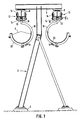
- Figures 1 and 2 you can see a three-legged support 2, which is anchored below on foundation blocks 4 to the ground and which carries a cross member 6 in the form of an I-profile at the top.
- a large number of such supports 2 are provided along the transport path at a mutual distance of 5 to 30 m, depending on the design of the transport device and on the weight of the goods to be transported per unit length of transport path.
- the cross member 6 extends on both sides of the support 2.
- a longitudinal member 8 in the form of an I-profile is fastened in each of its two end regions.
- the longitudinal beams 8 extend from support 2 to support 2 in the specified length.
- a traveling field stator 10 is attached to the underside of each side member 8.
- the traveling field stator 10 consists of a laminated laminated core in the longitudinal direction and has on the underside a series of grooves, not shown, which are arranged at a uniform distance and run transversely to the longitudinal direction of the transport path.
- a three-phase traveling field winding, for example, is meandered in these grooves.
- FIGs 1 and 2 you can also see movement elements in the form of trolleys 12.
- On each of the trolleys are eight rolling elements in the form of wheels 14, rotatably mounted, in such a way that four wheels below the lower flange of the side member 8 and four wheels are located above the lower flange of the side member 8, the arrangement with respect to the vertical flange of the side member 8 and viewed from the side of the trolley 12 being symmetrical.
- the upper wheels 14 can on the top of the lower flange of the Longitudinal beam 8 run out, and the lower wheels 14 can run on the underside of the lower flange of the longitudinal beam 8.
- the gap between the circumference of the lower wheels 14 and the circumference of the upper wheels 14 is somewhat larger than the thickness of the lower flange of the side member 8.
- the upper and / or the lower wheels 14 are provided with wheel rims for lateral guidance.
- Each trolley 12 is provided with a row of permanent magnets 16 extending in the transport direction such that the permanent magnet row below the traveling field stator 10 is opposite it with an air gap distance a.
- the permanent magnets 16 have alternating polarity in the longitudinal direction of the transport path and a spacing that corresponds to three times the arrangement of the grooves in the traveling field stator 10.
- a synchronous linear motor is formed by the traveling field stator 10 and the row of permanent magnets 16.
- This linear motor delivers both propulsive forces and vertically upward load-bearing forces, wherein the interaction of the wheels 14 with the side member 8 maintains the air gap distance a. If the weight to be carried by the trolley 12 is greater than the magnetic load capacity, the upper wheels 14 provide the required load capacity. If the weight to be carried by the scraper 12 is less than the magnetic load capacity, it is ensured by rolling the lower wheels 14 on the side member 8 that the permanent magnets 16 do not come into physical contact with the traveling field stator 10.
- a support element 18 which essentially has the shape of a three-quarter circular bracket, hangs around an axis lying in the longitudinal direction of the transport path, the "open quarter" of which points obliquely upwards from the support 2.
- the trolleys 12 have a mutual distance of one to ten m depending on the weight and amount of the goods to be transported.
- a conveyor belt 20 made of appropriately thick, possibly reinforced rubber is inserted into the lower, semicircular area of the brackets 18 and fastened to the brackets 18 on the right and left.
- the conveyor belt 20 extends from bracket 18 to bracket 18 over a partial length of the entire transport path.
- the individual trolleys 12 are connected to one another by longitudinal connectors in the form of rods 22 articulated on the trolleys 12.
- the individual brackets 18 are connected to one another by conveyor belt tightening longitudinal connectors in the form of rods 24 articulated on the brackets in order to relieve the brackets 18 of bending forces.
- the rods 22 and 24 can either connect a partial number of the brackets 18 to one another so that separate conveyor belt sections are created, or all brackets 18 of the entire transport device.
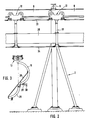
- partial areas 26 of the brackets 18 are pivoted downward in an unloading area about an axis lying in the longitudinal direction of the transport path (cf. FIG. 3). These sections 26 are each the quarter of the respective bracket 18 which is adjacent to the free end of the bracket 18. When the respective section 26 is folded down, the longitudinal edge of the conveyor belt 20 attached to it is carried downward, so that the conveyor belt 20 essentially has the shape when unloaded occupies an inclined surface inclined outwards and downwards.
- the transported goods G consequently slide outwards and downwards from the transport device in the unloading area, the unloading being able to be supported by mechanical wipers and / or being cleaned, for example by spraying with water.
- Each section is locked with the remaining bracket 18, which has the shape of an upright semicircle, by a latch 28 in the folded-up state.
- a contact surface 30 is provided in the respective unloading area, which lifts the pawls 28 traveling over it, as a result of which the lock is released and the respective partial area 26 claps down under the effect of gravity and / or the weight of the goods to be transported G.
- the respective partial area 26 is raised by an additional contact surface (not shown) acting on it, or by spring force or the like, so that it returns to the normal position latched in again.
- the longitudinal members 8 attached to the left ends of the cross members 6 form a forward guide of the conveyor belt 20 for the usually loaded transport route, while the longitudinal members attached to the right ends of the cross members 6 a return guide of the conveyor belt 20, usually in the unloaded state.
- the underside of the traveling field stator 10 can be provided higher on the back guide than on the outward guide, so that a larger air gap distance a is created in order to take into account the lower load capacity of the linear motor required there. This possibility is not shown in Figures 1 to 3. It goes without saying that the outward and return journeys are connected to one another by corresponding arches at the end of the transport route.
- Mam can also provide that the partial regions 26 of the stirrups 18 are not rigidly locked to the rest of the stirrups 18 in the normal state, but can pivot even more inwards.
- the conveyor belt 20 can take on a shape that is more compressed than semicircular at the top in curves of the transport path.
- FIGS. 4 shows a transport device without separate support elements for the conveyor belt 20.
- the two edges 32 running in the longitudinal direction of the transport path are attached to trolleys 12, 32 separate trolleys 12 per longitudinal edge.
- the longitudinal members 8 and the trolleys 12 are inclined downwards. placed inside, so that there is an upwardly open, concave, approximately parabolic shape of the conveyor belt 20 in cross section and a continuation of this shape in the alignment of the longitudinal beams 8, whereby the trolleys 12 are substantially relieved of transverse forces.
- the trolleys 12 can be connected to one another by longitudinal connectors, but need not be.
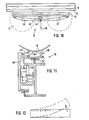
- the longitudinal beam 81-Profi has a middle flange 34 which is welded on approximately in the middle and pointing outwards.
- the traveling field stator 10 is fastened to the middle flange 34 at the bottom.
- Flange-free wheels 14 with a horizontal axis are located in the space between the upper flange and the central flange 34 of the side member 8 and can therefore run up both above and below.
- the side guide take over side guide wheels 14 ', which run on the vertical flange 36 of the side member 8.
- the embodiment according to FIG. 6 differs from the embodiment according to FIG. 5 in that the vertical flange 36 of the longitudinal member 8 is extended upwards and that the lower flange of the longitudinal member 8 has an extension 38 pointing upwards at one end. Pairs of side guide wheels 14 cooperate with the extension of the vertical flange 36 and the extension 38.
- the upper horizontal flange of the longitudinal beam 8 is extended on one side by a welded plate 40.
- the plate 40 carries the traveling field stator 10 on its underside.
- Upper wheels 14 can roll on the upper side of the upper horizontal flange and on the upper side of the plate 40, while lower wheels 14 can roll on the underside of the upper horizontal flange and on the underside of the plate 40.
- the lateral guidance is carried out by lateral guide wheels or wheel flanges (not shown) on at least some of the wheels 14.
- two longitudinal beams 8 with an I-profile are provided instead of a longitudinal beam 8, which are connected to one another via spaced, U-shaped cross connectors 19 located below.
- a traveling field stator 10 is attached below each longitudinal beam 8.
- the trolley 12 thus formed carries a support element 18 at the top, which in turn carries a transport goods receptacle.
- the longitudinal beam 8 has an I-profile, on the upper flange of which spaced-apart cross beams 11 are fastened, at the projecting ends of which a longitudinal angular profile is attached on the left and right, the open side of which points outwards-downwards.
- Wheels 14 run above and below on the horizontal legs of the angle profiles, while cornering wheels run on the outside on both sides of the vertical legs.
- Two traveling field stators 10 are attached to the right and left under the projecting ends of the cross beams 11.
- the entire arrangement is symmetrical with respect to a vertical central plane, the wheels and permanent magnets 16 on the left being connected to the wheels and permanent magnets 16 on the right via a bracket 17 which essentially has the shape of a U which overlaps the longitudinal member 8 and is open at the bottom and carries on its upper side a concave support element 18 which is open at the top.
- the conveyor belt not shown, is inserted into the support elements 18 of a row of the spaced-apart trolleys 12 described.
- the wheels 14 and / or the side guide wheels 14 ' are made of plastic, which is low-maintenance and can be carried out due to the relatively low wheel load.
- the conveyor belt can either be arranged hanging on the trolleys 12 or also standing thereon. It is preferably ensured that - viewed in cross-section - the center of gravity of the loaded conveyor belt in the vertical direction is essentially above or below the linear motor or the wheels 14 acting in the vertical direction in order to have to absorb the smallest possible tilting moments about an axis lying in the longitudinal direction of the transport path .
- an articulated suspension about an axis located in the longitudinal direction of the transport path is advantageous in this context.
- the trolleys 12 have a series of permanent magnets 16 in the opposing position in the traveling field stator 10.
- FIG. 10 and 11 show two possibilities for mechanically adapting the running gap distance a to the loading state of the conveyor belt 20.
- lower wheels 14 are not rigidly attached to the trolley 12. Rather, a pivotably arranged lever 42 leads from the front end of the trolley 12 to the rear and from the rear end of the trolley 12 a pivotable lever 42 leads to the front.
- the two levers 42 are connected to one another at their free ends.
- a tension coil spring 46 is arranged between this connection area 44 and the trolley body.
- a pair of wheels 14 is rotatably mounted on each of the levers 42, in each case closer to the articulation point of the lever 42 than to the connection point 44.
- the conveyor belt 20 is attached to the connection point 44 by means of a support element (not shown).
- the linear motor provides a larger magnetic lifting capacity in the vertical direction.
- the embodiment according to FIG. 10 corresponds essentially to the embodiment according to FIG. 6 in terms of the design of the longitudinal beam 8 and the geometry of the arrangement of the linear motor and the wheels 14 and 14 '.
- the top of the trolley is interposed with compression coil springs 46 an approximately semicircular, upwardly open support element 18 is attached.
- the conveyor belt (not shown) lies in the support element 18.
- the wheel 14 acting in the vertical direction is mounted on the trolley 12 so as to be vertically displaceable relative to it.
- a substantially horizontally extending lever 42 ' is articulated on the trolley 12.
- the free end of the lever 42 ′ which extends transversely to the longitudinal direction of the transport path, is articulated on the support element 18.
- the distance between the two longitudinal beams 8 and at the same time, logically, their angular orientation along the transport path can also be made different.
- the distance between the two longitudinal beams 8 and their operative orientation such that the cross section of the conveyor belt 20 is essentially horizontal or is tensioned only with a slight sag, which enables particularly convenient unloading. for example by deflecting the conveyor belt by approximately 180 ° similar to conventional conveyor belt devices.
- the almost horizontal or only slightly sagging shape of the conveyor belt 20 in cross section can also be supported by support by means of rollers, rollers or the like, mainly in the middle of the conveyor belt.
- the return of the conveyor belt 20 can be provided in a space-saving manner above or below the guide . It generally applies that the return of the conveyor belt 20 can take place not only next to but also above or below the outward route.
- the arrangement shown consisting of side member 8, trolley 12 with wheels 14 or 14 ', traveling field stator 10 and row of permanent magnets 16, viewed only in cross section, can be provided only once or added symmetrically in duplicate.
- the connection to the hanging or standing conveyor belt goes laterally next to the one longitudinal beam 8 upwards or downwards.
- the connection to the hanging or standing conveyor belt is usually up or down between the two longitudinal beams 8.
- the left and right trolleys 12 are either mechanically connected transversely to one another or not.
- the embodiment according to FIG. 5 is also particularly suitable for paired arrangement of the longitudinal beams 8.
- the entire transport route (there and back) is not occupied by a continuous traveling field stator 10, but a plurality of traveling field stator sections are provided distributed in the longitudinal direction.
- the traveling field stator sections are preferably substantially shorter than the conveyor belt sections if the entire conveyor belt is divided into separate conveyor belt sections.
- Linear motor units which are fed and controlled by a power supply unit mounted in the guideway and which are shorter than conveyor belt sections are referred to as linear motor elements.
- Such an element is preferably controlled such that a conveyor belt section entering the area of the respective motor element is detected by one or more sensors attached to the linear motor section in a stationary manner, the respective motor element is switched on or off and synchronized with the permanent magnet pole speed of the conveyor belt section.
- each motor element Due to the subdivision into linear motor elements, each motor element only needs a smaller, installed or to be applied power, which occurs in large numbers in the form of frequency converters with control, power supply, etc. and is therefore not too expensive from a manufacturing point of view.
- Several transport speeds can be stored in the control of each motor element, which can be called up either centrally or by influencing conveyor belt sections. In this way, the possibility of different speeds and the different spacing of the conveyor belt sections described further above can be realized comparatively easily.
- the conveyor belt sections travel slower in certain areas, for example on a free transport route without narrow curvatures, and in certain other areas, for example in loading areas, unloading areas, transport route sections with narrower curvatures.
- the motor elements are preferably shorter than the conveyor belt sections, for example a few meters long compared to a conveyor belt section length of several 100 meters.
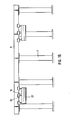
- Fig. 12 schematically illustrates a switch construction for the case of longitudinal beams 8 with I-profile.
- Both the upper flange and the lower flange of the longitudinal beam 8 are provided from the side with, for example, sawn-in, transverse incisions. This gives the side member 8 sufficient elasticity in the transverse direction so that it can be bent at the appropriate length elastically at one end by the required distance in the transverse direction in order to make the connection to a branching side member.
- FIG. 13 shows in the form of an electrical block circuit diagram an embodiment of the transport device with self-control.
- the traveling field stator ST is divided into a plurality of stator sections ST, of which only three stator sections ST5, ST6 and ST7 are shown in full in FIG. 13.
- Each of these stator sections is assigned an energy control unit E5, E6 or E7, to which a switching device belongs, by means of which the switch provided by the respective energy supply unit Power can be connected to the associated stator section.
- Probes S are arranged along the stator ST, which react to signal generators SG1 and SG2 on the linear motor rotor L. In the embodiment shown in FIG.
- two probes S51, S52 or S61, S62 or S71, S72 are assigned to each stator section, one of which is located in the front and the other in the rear end region of the respective stator section. If, for example, in the relative position shown in FIG. 13 between the linear motor rotor L and the linear motor stator ST, the signal generator SG1 lying in front in the direction of travel reaches the sensor area of the sensor S51, this causes the driving power provided by the energy supply unit E6 to be switched on to the stator section ST6. Then when the signal generator SG2 of the linear motor rotor L lying in the direction of travel reaches the sensor area of the sensor S62, the energy supply unit E5 is switched off by the stator section ST5.
- Either the permanent magnets which are preferably used for the linear motor rotor itself or signal generator magnets additionally arranged on the linear motor rotor L can be used as signal generators SG1 and SG2. Hall probes are then preferably used for the probes S along the stator ST.
- the driving profile can be made variable with the help of a driving program number control in a technically quite simple way.
- a memory is assigned to each energy supply unit, in which a number of different driving speed control signals corresponding to the number of predetermined controllable driving programs can be stored.
- the memories are connected via a common bus line BL to a control point C, from which the memories in the individual energy supply units are given the driving program numbers corresponding to a desired driving profile.
- Each energy supply unit can then deliver to the associated stator section a local driving performance corresponding to the selected driving program number.
- the driving performance corresponding to a certain driving program number can be different for different stator sections.
- control station C only a single driving program number to bus line BL, which is then assigned in the individual energy supply units to the location-specific individual driving performance for the selected driving profile.
- the control point C can be assigned to all stator sections of the transport device or only to a part of the stator sections, further groups of stator sections then being controlled by a further control point.
- a steady-state route follows an acceleration route and the journey is ended after passing through a braking route.
- Four speed profiles 0 (standing) to 3 (maximum speed) can be selected using four driving program numbers.
- different and more complicated driving profiles will be required. For example, intermediate accelerations and intermediate decelerations will be required where there is uphill or downhill or around bends and, in the case of a transport device according to the invention in the manner of a conveyor belt device, only speeds 0 that differ from 0 will occur in the loading and unloading zones except when driving program 0 is selected.
- FIG. 15 illustrates the possibility of dividing the conveyor belt into a plurality of conveyor belt sections 20 'which travel the transport route at a mutual distance in the direction of travel. Overall, the construction is analogous to the transport device shown in more detail in FIG. 2.
Landscapes
- Engineering & Computer Science (AREA)
- Mechanical Engineering (AREA)
- Non-Mechanical Conveyors (AREA)
- Structure Of Belt Conveyors (AREA)
- Linear Motors (AREA)
- Belt Conveyors (AREA)
Priority Applications (1)
| Application Number | Priority Date | Filing Date | Title |
|---|---|---|---|
| AT84112458T ATE29123T1 (de) | 1983-10-20 | 1984-10-16 | Transporteinrichtung nach art einer foerderbandeinrichtung. |
Applications Claiming Priority (2)
| Application Number | Priority Date | Filing Date | Title |
|---|---|---|---|
| DE3338199 | 1983-10-20 | ||
| DE19833338199 DE3338199A1 (de) | 1983-10-20 | 1983-10-20 | Transporteinrichtung nach art einer foerderbandeinrichtung |
Publications (2)
| Publication Number | Publication Date |
|---|---|
| EP0141334A1 EP0141334A1 (de) | 1985-05-15 |
| EP0141334B1 true EP0141334B1 (de) | 1987-08-26 |
Family
ID=6212363
Family Applications (1)
| Application Number | Title | Priority Date | Filing Date |
|---|---|---|---|
| EP84112458A Expired EP0141334B1 (de) | 1983-10-20 | 1984-10-16 | Transporteinrichtung nach Art einer Förderbandeinrichtung |
Country Status (6)
| Country | Link |
|---|---|
| US (1) | US4792036A (enExample) |
| EP (1) | EP0141334B1 (enExample) |
| JP (1) | JPS60112517A (enExample) |
| AT (1) | ATE29123T1 (enExample) |
| CA (1) | CA1221330A (enExample) |
| DE (2) | DE3338199A1 (enExample) |
Families Citing this family (33)
| Publication number | Priority date | Publication date | Assignee | Title |
|---|---|---|---|---|
| DE3741054C2 (de) * | 1987-12-04 | 1997-03-13 | Ketterer Klaus | Gurtbandförderer mit Linearantrieb |
| US5664660A (en) * | 1989-02-24 | 1997-09-09 | Kosan Crisplant A/S | Sorter conveyor |
| US5054601A (en) * | 1989-09-19 | 1991-10-08 | Quipp, Incorporated | Sorting conveyor |
| ZA907711B (en) * | 1989-11-01 | 1992-01-29 | Lewin Heinz Ulrich | Conveyor belt |
| US5172803A (en) * | 1989-11-01 | 1992-12-22 | Lewin Heinz Ulrich | Conveyor belt with built-in magnetic-motor linear drive |
| JPH04145919A (ja) * | 1990-10-04 | 1992-05-19 | Kotaro Matsui | 巻線多重回転機 |
| JP2984359B2 (ja) * | 1990-11-20 | 1999-11-29 | ソニー株式会社 | 磁気浮上搬送システム及び同システム用搬送車 |
| US5199548A (en) * | 1991-10-03 | 1993-04-06 | Hitachi Kiden Kogyo K.K. | Controls in a goods assorting device |
| US5398804A (en) * | 1993-02-15 | 1995-03-21 | E+PK Ingenieurburo fur Entwicklung und Planung | Curved conveyor belt with supporting frame devoid of belt band rollers |
| EP0611712A3 (de) * | 1993-02-15 | 1994-08-31 | E + Pk Ingenieurbüro | Kurvenbandförderer mit gurtbandrollenfreiem Traggerüst |
| DE4323127A1 (de) * | 1993-02-15 | 1994-08-18 | E & Pk Ingbuero | Kurvenbandförderer mit gurtbandrollenfreiem Traggerüst |
| US5699894A (en) * | 1995-10-06 | 1997-12-23 | Fmc Corporation | Cable driven conveyor system |
| US6206170B1 (en) * | 1996-04-15 | 2001-03-27 | Mantissa Corporation | Control system for a tilt tray sorter |
| DE19722376A1 (de) * | 1996-05-29 | 1997-12-04 | Heidelberger Druckmasch Ag | Bogentransportsystem für eine Rotationsdruckmaschine |
| SG74601A1 (en) * | 1996-11-15 | 2000-08-22 | Ishikawajima Harima Heavy Ind | System for traversing trolley |
| US5975277A (en) * | 1997-10-31 | 1999-11-02 | Motion Systems, L.C. | LIM drive conversion kit |
| DE60135468D1 (de) * | 2000-09-08 | 2008-10-02 | Lawrence Hugh Chapman | Transportsystem |
| GB0023370D0 (en) * | 2000-09-23 | 2000-11-08 | Logan Fabricom Ltd | A material sortation system |
| IT1319594B1 (it) * | 2000-12-20 | 2003-10-20 | Cml Handling Technology S P A | Apparecchiatura e metodo per l'attivazione ed il controllo delleunita' di smistamento in una macchina smistatrice |
| WO2002057161A2 (en) * | 2001-01-22 | 2002-07-25 | Crisplant A/S | Sorter conveyor |
| US20060011093A1 (en) * | 2002-07-26 | 2006-01-19 | Viggo Jensen | Conveyor and a method of providing a driving force to a conveyor |
| WO2004011351A2 (en) * | 2002-07-26 | 2004-02-05 | Crisplant A/S | A conveyor and a method of providing a driving force to a conveyor |
| DE10351619A1 (de) * | 2003-11-05 | 2005-06-09 | Heidelberger Druckmaschinen Ag | Transportsystem in einer Bedruckstoff verarbeitenden Maschine |
| US7287749B2 (en) | 2003-11-05 | 2007-10-30 | Heidelberger Druckmaschinen Ag | Transport system in a machine that processes printing material |
| US6971507B2 (en) * | 2003-12-10 | 2005-12-06 | Jon Forman | Magnetic conveyor support |
| CN101689796B (zh) * | 2007-04-16 | 2012-08-08 | 克瑞斯普兰股份有限公司 | 具有线性同步马达驱动的分类系统 |
| EP2746880B1 (en) * | 2012-12-21 | 2018-04-25 | Robert Bosch Gmbh | Carriers synchronization in a conveying system of a machine |
| DE102013000372A1 (de) * | 2013-01-11 | 2014-07-17 | Beumer Gmbh & Co. Kg | Fördervorrichtung mit konkavem Gurt |
| US9132873B1 (en) | 2013-03-14 | 2015-09-15 | Kuka Systems Corporation North America | Flexible conveyance system |
| US20140262680A1 (en) * | 2013-03-14 | 2014-09-18 | Kuka Systems Corporation North America | Flexible Conveyance System |
| MX344531B (es) | 2013-03-14 | 2016-12-19 | Kuka Systems North America Llc | Sistema de transporte flexible. |
| WO2016033583A1 (en) | 2014-08-29 | 2016-03-03 | Mantissa Corporation | Conveyor system wheel failure detection and remediation |
| CN109677510B (zh) * | 2018-11-05 | 2024-01-26 | 浦生(上海)工业自动化设备有限公司 | 一种流水线运输车车头及其使用方法 |
Citations (2)
| Publication number | Priority date | Publication date | Assignee | Title |
|---|---|---|---|---|
| DE539726C (de) * | 1923-03-31 | 1931-12-02 | H R Gillespie | Verfahren zur Herstellung von Lacken |
| DE1183011B (de) * | 1964-02-20 | 1964-12-03 | Dipl Berging Werner Schaeffer | Gehaengefoerderer mit Schlauchbandzuegen |
Family Cites Families (17)
| Publication number | Priority date | Publication date | Assignee | Title |
|---|---|---|---|---|
| DE710220C (de) * | 1938-06-04 | 1941-09-08 | Miag Muehlenbau Und Ind Akt Ge | Doppelplansichter |
| DE736256C (de) * | 1941-01-21 | 1943-06-10 | Demag Ag | Einrichtung zur Kuehlung von ortsbeweglichen Maschinensaetzen |
| DE1030249B (de) * | 1955-05-02 | 1958-05-14 | Hugo Kleusberg | Gehaengefoerderband mit Muldenbuegeln |
| GB854644A (en) * | 1957-03-13 | 1960-11-23 | Wilhelm Grube | Improvements in a travelling gear for suspension railways with fixed tracks |
| SU122072A1 (ru) * | 1959-01-05 | 1959-11-30 | А.Н. Смирнов | Устройство дл транспортировки и раскладки холстов на чесальные машины |
| DE1218954B (de) * | 1964-10-24 | 1966-06-08 | Demag Zug Gmbh | Verfahren und Einrichtung zum Abbremsen pendelnde Lasten tragender Laufkatzen od. dgl. |
| US3616762A (en) * | 1968-09-25 | 1971-11-02 | Linerail Manutention Par Moteu | Overhead conveyor system |
| FR2032064A5 (enExample) * | 1969-02-17 | 1970-11-20 | Merlin Gerin | |
| DE1931901A1 (de) * | 1969-06-24 | 1971-01-07 | Schaeffer Dipl Berging Werner | Schwebebahn fuer Trogband- und Gueterzuege |
| DE2135970A1 (de) * | 1971-07-19 | 1973-02-08 | Rheinische Braunkohlenw Ag | Foerdereinrichtung |
| DE2207930A1 (de) * | 1972-02-19 | 1973-08-23 | Bergwerksverband Gmbh | Zugmaschinenantrieb |
| DE2339060C3 (de) * | 1973-08-01 | 1980-12-18 | Magnet-Bahn Gmbh, 8130 Starnberg | Magnetische Trag- und Vortriebseinrichtung fUr ein längs eines Fahrweges bewegbares Fahrzeug |
| GB1513561A (en) * | 1976-04-28 | 1978-06-07 | Drysys King Conveyors Ltd | Conveyors |
| US4284010A (en) * | 1977-07-11 | 1981-08-18 | The Port Authority Of New York And New Jersey | Conveyance system |
| DE2933450A1 (de) * | 1979-08-17 | 1981-02-26 | Heidelberg Goetz | Synchroner linearmotor, insbesondere zum antrieb von magnetschwebefahrzeugen |
| ZA822693B (en) * | 1981-04-21 | 1983-02-23 | Brockway Eng Co Ltd | Driving endless flexible belts |
| SU1047790A1 (ru) * | 1982-05-17 | 1983-10-15 | Ордена Октябрьской Революции И Ордена Трудового Красного Знамени Автомобильный Завод Им.Ленинского Комсомола | Грузова тележка подвесного конвейера |
-
1983
- 1983-10-20 DE DE19833338199 patent/DE3338199A1/de active Granted
-
1984
- 1984-10-16 DE DE8484112458T patent/DE3465585D1/de not_active Expired
- 1984-10-16 AT AT84112458T patent/ATE29123T1/de not_active IP Right Cessation
- 1984-10-16 EP EP84112458A patent/EP0141334B1/de not_active Expired
- 1984-10-18 CA CA000465829A patent/CA1221330A/en not_active Expired
- 1984-10-20 JP JP59221103A patent/JPS60112517A/ja active Pending
-
1987
- 1987-06-26 US US07/068,817 patent/US4792036A/en not_active Expired - Fee Related
Patent Citations (2)
| Publication number | Priority date | Publication date | Assignee | Title |
|---|---|---|---|---|
| DE539726C (de) * | 1923-03-31 | 1931-12-02 | H R Gillespie | Verfahren zur Herstellung von Lacken |
| DE1183011B (de) * | 1964-02-20 | 1964-12-03 | Dipl Berging Werner Schaeffer | Gehaengefoerderer mit Schlauchbandzuegen |
Also Published As
| Publication number | Publication date |
|---|---|
| CA1221330A (en) | 1987-05-05 |
| US4792036A (en) | 1988-12-20 |
| JPS60112517A (ja) | 1985-06-19 |
| DE3338199C2 (enExample) | 1987-11-26 |
| DE3338199A1 (de) | 1985-05-09 |
| DE3465585D1 (en) | 1987-10-01 |
| ATE29123T1 (de) | 1987-09-15 |
| EP0141334A1 (de) | 1985-05-15 |
Similar Documents
| Publication | Publication Date | Title |
|---|---|---|
| EP0141334B1 (de) | Transporteinrichtung nach Art einer Förderbandeinrichtung | |
| EP2099640B1 (de) | Magnetschwebefahrzeug mit wenigstens einem magnetsystem | |
| DE2261936C3 (de) | Förderwegweiche zur Übergabe von Stückgut | |
| EP0356370B1 (de) | Magnetkraftsystem für reibungsarmen Transport von Lasten | |
| EP1401743B1 (de) | Transportwagen zum ein- und auslagern von transportgut | |
| EP0059443B1 (de) | Fahrzeug, das gegenüber einem Fahrweg mit Hilfe einer anziehenden magnetischen Einrichtung gehalten werden kann | |
| DE3612500C2 (enExample) | ||
| EP3501878A1 (de) | Transporteinrichtung in form eines langstatorlinearmotors | |
| EP2195186B1 (de) | Magnetschwebefahrzeug und verfahren zum anheben und/oder absetzen desselben | |
| DE1947980A1 (de) | Vorrichtung zur Regelung der Geschwindigkeit von Foerderfahrzeugen mit einem linearen Motor | |
| DE2711994C3 (de) | Fahrzeug, das gegenüber einem Fahrweg mit Hilfe einer anziehenden magnetischen Einrichtung und einer Zusatzkrafteinrichtung gehalten wird | |
| WO2007039196A1 (de) | Rollenbahnförderer sowie rollenbahnsystem zum aufbau eines solchen | |
| DE2310718B2 (de) | Magnetschwebebahn | |
| DE2309711A1 (de) | Schienengebundenes transportsystem | |
| EP0137471B1 (de) | Stauketten-Fördereinrichtung für hängende Stückgüter | |
| DE60310466T2 (de) | Automatisiertes Parksystem mit bewegbaren Bühnen für Aufnahme und Transport von Fahrzeugen zu vorher ausgewählten Parkplätzen | |
| DE69415758T2 (de) | Transportsystem | |
| DE69101772T2 (de) | Elektrische Oberleitungsversorgungseinrichtung für Schienenfahrzeuge mit einer biegsamen und horizontal schwenkbaren Leitung sowie elektrisches Leistungskabel mit einer solchen Vorrichtung. | |
| AT500227B1 (de) | Transportwagen zum ein- und auslagern von transportgut | |
| DE10044612A1 (de) | Kippstation für Stückgutförderer | |
| DE1917853A1 (de) | Elektromagnetisch antreibbares Luftkissenfahrzeug | |
| EP1769572A1 (de) | Fahrzeug zum einlegen wenigstens einer elektrischen leitung in die nuten eines langstators | |
| DE1259782C2 (de) | Elektrofoerderbahn zum Transport von Akten oder aehnlichem Foerdergut in Gebaeuden | |
| CH461362A (de) | Förderanlage für Behälter oder Fördergutträger | |
| EP1074764A2 (de) | Vorrichtung zum Führen und Stützen einer Schleppkette |
Legal Events
| Date | Code | Title | Description |
|---|---|---|---|
| PUAI | Public reference made under article 153(3) epc to a published international application that has entered the european phase |
Free format text: ORIGINAL CODE: 0009012 |
|
| AK | Designated contracting states |
Designated state(s): AT BE CH DE FR GB IT LI NL SE |
|
| 17P | Request for examination filed |
Effective date: 19851104 |
|
| 17Q | First examination report despatched |
Effective date: 19860411 |
|
| GRAA | (expected) grant |
Free format text: ORIGINAL CODE: 0009210 |
|
| AK | Designated contracting states |
Kind code of ref document: B1 Designated state(s): AT BE CH DE FR GB IT LI NL SE |
|
| REF | Corresponds to: |
Ref document number: 29123 Country of ref document: AT Date of ref document: 19870915 Kind code of ref document: T |
|
| ITF | It: translation for a ep patent filed | ||
| REF | Corresponds to: |
Ref document number: 3465585 Country of ref document: DE Date of ref document: 19871001 |
|
| ET | Fr: translation filed | ||
| PLBE | No opposition filed within time limit |
Free format text: ORIGINAL CODE: 0009261 |
|
| STAA | Information on the status of an ep patent application or granted ep patent |
Free format text: STATUS: NO OPPOSITION FILED WITHIN TIME LIMIT |
|
| 26N | No opposition filed | ||
| PGFP | Annual fee paid to national office [announced via postgrant information from national office to epo] |
Ref country code: GB Payment date: 19900727 Year of fee payment: 7 |
|
| PGFP | Annual fee paid to national office [announced via postgrant information from national office to epo] |
Ref country code: SE Payment date: 19901011 Year of fee payment: 7 |
|
| PGFP | Annual fee paid to national office [announced via postgrant information from national office to epo] |
Ref country code: FR Payment date: 19901018 Year of fee payment: 7 |
|
| PGFP | Annual fee paid to national office [announced via postgrant information from national office to epo] |
Ref country code: CH Payment date: 19901022 Year of fee payment: 7 |
|
| ITTA | It: last paid annual fee | ||
| PGFP | Annual fee paid to national office [announced via postgrant information from national office to epo] |
Ref country code: NL Payment date: 19901031 Year of fee payment: 7 Ref country code: AT Payment date: 19901031 Year of fee payment: 7 |
|
| PGFP | Annual fee paid to national office [announced via postgrant information from national office to epo] |
Ref country code: BE Payment date: 19901113 Year of fee payment: 7 |
|
| PG25 | Lapsed in a contracting state [announced via postgrant information from national office to epo] |
Ref country code: GB Effective date: 19911016 Ref country code: AT Effective date: 19911016 |
|
| PG25 | Lapsed in a contracting state [announced via postgrant information from national office to epo] |
Ref country code: SE Effective date: 19911017 |
|
| PG25 | Lapsed in a contracting state [announced via postgrant information from national office to epo] |
Ref country code: LI Effective date: 19911031 Ref country code: CH Effective date: 19911031 Ref country code: BE Effective date: 19911031 |
|
| BERE | Be: lapsed |
Owner name: HEIDELBERG GOTZ Effective date: 19911031 |
|
| PG25 | Lapsed in a contracting state [announced via postgrant information from national office to epo] |
Ref country code: NL Effective date: 19920501 |
|
| GBPC | Gb: european patent ceased through non-payment of renewal fee | ||
| NLV4 | Nl: lapsed or anulled due to non-payment of the annual fee | ||
| PG25 | Lapsed in a contracting state [announced via postgrant information from national office to epo] |
Ref country code: FR Effective date: 19920630 |
|
| REG | Reference to a national code |
Ref country code: CH Ref legal event code: PL |
|
| REG | Reference to a national code |
Ref country code: FR Ref legal event code: ST |
|
| EUG | Se: european patent has lapsed |
Ref document number: 84112458.9 Effective date: 19920510 |
|
| PGFP | Annual fee paid to national office [announced via postgrant information from national office to epo] |
Ref country code: DE Payment date: 19971217 Year of fee payment: 14 |
|
| PG25 | Lapsed in a contracting state [announced via postgrant information from national office to epo] |
Ref country code: DE Free format text: LAPSE BECAUSE OF NON-PAYMENT OF DUE FEES Effective date: 19990803 |