EP0141068A2 - Tauchkolben-Dosierpumpe - Google Patents
Tauchkolben-Dosierpumpe Download PDFInfo
- Publication number
- EP0141068A2 EP0141068A2 EP84109239A EP84109239A EP0141068A2 EP 0141068 A2 EP0141068 A2 EP 0141068A2 EP 84109239 A EP84109239 A EP 84109239A EP 84109239 A EP84109239 A EP 84109239A EP 0141068 A2 EP0141068 A2 EP 0141068A2
- Authority
- EP
- European Patent Office
- Prior art keywords
- piston
- metering
- pump
- plunger
- wear part
- Prior art date
- Legal status (The legal status is an assumption and is not a legal conclusion. Google has not performed a legal analysis and makes no representation as to the accuracy of the status listed.)
- Granted
Links
- 238000007789 sealing Methods 0.000 claims description 15
- 239000007788 liquid Substances 0.000 claims description 5
- 238000002347 injection Methods 0.000 claims description 2
- 239000007924 injection Substances 0.000 claims description 2
- XLYOFNOQVPJJNP-UHFFFAOYSA-N water Substances O XLYOFNOQVPJJNP-UHFFFAOYSA-N 0.000 claims description 2
- 230000001681 protective effect Effects 0.000 claims 1
- 230000002349 favourable effect Effects 0.000 description 2
- 239000003795 chemical substances by application Substances 0.000 description 1
- 238000002425 crystallisation Methods 0.000 description 1
- 230000008025 crystallization Effects 0.000 description 1
- 230000006735 deficit Effects 0.000 description 1
- 230000000694 effects Effects 0.000 description 1
- 238000004519 manufacturing process Methods 0.000 description 1
- 230000000717 retained effect Effects 0.000 description 1
- 239000000243 solution Substances 0.000 description 1
Images
Classifications
-
- F—MECHANICAL ENGINEERING; LIGHTING; HEATING; WEAPONS; BLASTING
- F04—POSITIVE - DISPLACEMENT MACHINES FOR LIQUIDS; PUMPS FOR LIQUIDS OR ELASTIC FLUIDS
- F04B—POSITIVE-DISPLACEMENT MACHINES FOR LIQUIDS; PUMPS
- F04B13/00—Pumps specially modified to deliver fixed or variable measured quantities
Definitions
- the invention relates to a plunger metering pump with a metering piston designed as a plunger, preferably for metering an additional liquid into the injection point of a main liquid line, in particular into a water line.
- the metering pump can, for example, have a mechanical-hydraulic, mechanical-pneumatic or electric drive and is primarily arranged directly inside the metering agent container on its bottom.
- the medium to be dosed should always be higher than the pump cylinder.
- the invention has for its object to improve the plunger metering pump so that when wear occurs, a simple, quick and safe repair of the pump is possible without the need for an additional readjustment of the metered amount. Disassembly and Assembly of the pump should in particular be carried out in such a way that the position of the metering piston relative to its sealing element is exactly retained during the exchange.
- the solution according to the invention is characterized for the plunger metering pump described at the outset by an exchangeable pump module or a wear part insert.
- the pump module which preferably also contains the metering piston, is assigned a first contact edge, in particular in the lower part of the pump receptacle, which ensures the relative position required for operation during assembly.
- the Kolben Stahl h is approximately upper part of the pump module in the piston actuating ram of the pump formed Snap.
- the piston upper part of the pump module should expediently be assigned a further contact edge in the piston actuating plunger, which facilitates exact assembly.
- the interchangeable wear part insert or pump module according to the invention should contain, in addition to the aforementioned elements, in particular a metering check valve protecting the metering line against the pump cylinder and the sealing element sealing against the surrounding medium, and advantageously also the piston guide elements.
- a metering check valve protecting the metering line against the pump cylinder and the sealing element sealing against the surrounding medium
- the piston guide elements for handling it is favorable if the pump module is surrounded by an intermediate ring which on the one hand facilitates replacement and on the other hand protects the sealing elements from external impairments.
- a latchable connection of the pump module piston upper part to the actuating plunger of the piston is also advantageous. This means that a piston return spring can be dispensed with and the drive force can be reduced by the corresponding spring restoring force.
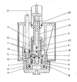
- the plunger metering pump shown in section and designated overall by 1 has a metering piston 2 designed as a plunger.
- the medium to be metered runs in the upper piston position 3 via inlet slots 4 into a cylinder space 5.
- the metering piston 2 moves downward in the direction of the arrow 6, the metering liquid present in the cylinder chamber 5 is expelled into the metering line 10 via the metering check valve 7, which is designed in particular as a ring valve, via the ring chamber 8 of the intermediate ring 9.
- the individual parts of the metering pump 1 which are primarily exposed to wear are combined in a separate wear part insert 11.
- the module change is an after adjust or readjust the specific dosage. not required.
- This advantage is achieved, inter alia, by a first contact edge 18 associated with the wear part insert 11 for the lower part of the pump receptacle 19. With the aid of a further contact edge 20 - namely between the upper piston guide part 16 and the piston actuating plunger or lever 21 - the relative position of the metering piston 2 to its sealing element 12 can be achieved can be guaranteed particularly safely.
- Another advantageous feature of the present metering pump is the snap-in connection of the piston guide upper part 16 and the piston actuating plunger 21. With the aid of this connection, the metering piston 2 is carried along during the upward movement in the direction of the arrow 22.
Landscapes
- Engineering & Computer Science (AREA)
- Mechanical Engineering (AREA)
- General Engineering & Computer Science (AREA)
- Details Of Reciprocating Pumps (AREA)
- Reciprocating Pumps (AREA)
- Fuel-Injection Apparatus (AREA)
- Structures Of Non-Positive Displacement Pumps (AREA)
- Control Of Non-Positive-Displacement Pumps (AREA)
Abstract
Description
- Die Erfindung betrifft eine Tauchkolben-Dosierpumpe mit als Tauchkolben ausgebildetem Dosierkolben, vorzugsweise zum Eindosieren einer Zusatzflüssigkeit in die Impfstelle einer Hauptflüssigkeitsleitung, insbesondere in eine Wasserleitung. Die Dosierpumpe kann beispielsweise einen mechanisch-hydraulischen, mechanisch-pneumatischen oder elektrischen Antrieb besitzen und wird vornehmlich direkt innerhalb des Dosiermittelbehälters auf dessen Boden angeordnet. Das zu dosierende Medium soll in jedem Fall höher als der Pumpenzylinder liegen.
- In der Praxis müssen mit solchen Pumpen auch Produkte dosiert werden, welche durch Auskristallisieren verschleißfördernd auf den Pumpenkolben sowie auf die Dicht- und Führungselemente wirken. Diese beanspruchten Bauelemente sind daher in relativ kurzen zeitlichen Abständen auszuwechseln. Der Nachteil ist umso gravierender, als bei bisher verwendeten Pumpen der Austausch der verschleißbehafteten Teile, insbesondere auch des Dosierkolbens, mit einer weitgehenden Demontage der gesamten Pumpe und nach der Remontage mit einem Neujustieren der Pumpe auf die jeweilige Dosiermenge verbunden ist.
- r Der Erfindung liegt die Aufgabe zugrunde, die Tauchkolben-Dosierpumpe so zu verbessern, daß bei Auftreten eines Verschleißes ein einfaches, schnelles und sicheres Instandsetzen der Pumpe ohne das Erfordernis einer zusätzlichen Neueinstellung der Dosiermenge möglich ist. Demontage und Montage der Pumpe sollen insbesondere so auszuführen sein, daß die Position des Dosierkolbens relativ zu seinem Dichtelement bei dem Austausch exakt erhalten bleibt. Die erfindungsgemäße Lösung ist für die eingangs beschriebene Tauchkolben-Dosierpumpe gekennzeichnet durch ein auswechselbares Pumpenmodul bzw. einen Verschleißteileinsatz.
- Dem vorzugsweise auch den Dosierkolben enthaltenden Pumpenmodul wird gemäß weiterer Erfindung eine erste Anlegekante, insbesondere im Unterteil der Pumpenaufnahme, zugeordnet, welche die für den Betrieb erforderliche Relativlage bei der Montage sicherstellt. Mit besonderem Vorteil wird das Kolbenführungsoberteil des Pumpenmoduls in den Kolbenbetätigungsstößel der Pumpe einrastend ausgebildet. Außerdem soll dem Kolbenoberteil des Pumpenmoduls zweckmäßig eine weitere, die exakte Montage erleichternde Anlegekante im Kolbenbetätigungsstößel zugeordnet werden.
- Demgemäß wird durch die Erfindung erreicht, daß der Wechsel des Pumpenmoduls als ganzes kein Neujustieren der beschriebenen Pumpe erfordert. Ferner bleibt bei zu gewährleistender enger Fertigungstoleranz des Pumnenmoduls die definierte Lage des Kolbendichtelements zu der Relativstellung des Dosierkolbens bei jedem Auswechseln des Pumpenmoduls erhalten.
- Der erfindungsgemäße, auswechselbare Verschleißteileinsatz bzw. Pumpenmodul soll neben den vorgenannten Elementen, insbesondere ein die Dosierleitung gegen den Pumpenzylinder schützendes Dosierrückschlagventil und das gegen das umgebende Medium abdichtende Dichtelement sowie vorteilhaft auch die Kolbenführungselemente enthalten. Für das Handhaben ist es günstig, wenn das Pumpenmodul von einem Zwischenring umgeben wird, der einerseits das Austauschen erleichtert und andererseits die Dichtelemente vor äußeren Beeinträchtigungen schützt. Ebenfalls vorteilhaft ist eine rastbare Verbindung des Pumpenmodul-Kolbenoberteils mit dem Betätigungsstößel des Kolbens. Dadurch können eine Kolbenrückholfeder entfallen und die Antriebskraft um die entsprechende Federrückstellkraft verringert werden.
- Anhand der schematischen Darstellung eines Ausführungsbeispiels werden weitere Einzelheiten der Erfindung erläutert.
- Die im Schnitt dargestellte und insgesamt mit 1 bezeichnete Tauchkolben-Dosierpumpe besitzt einen als Tauchkolben ausgebildeten Dosierkolben 2. Im hier interessierenden Zusammenhang läuft bei der oberen Kolbenstellung 3 das zu dosierende Medium über Einlaufschlitze 4 in einen Zylinderraum 5. Bei der Abwärtsbewegung des Dosierkolbens 2 in Pfeilrichtung 6 wird die im Zylinderraum 5 vorhandene Dosierflüssigkeit über das insbesondere als Ringventil ausgebildete Dosierrückschlagventil 7 über die Ringkammer 8 des Zwischenrings 9 in die Dosierleitung 10 ausgestoßen.
- Die vornehmlich dem Verschleiß ausgesetzten Einzelteile der Dosierpumpe 1 werden in einem separaten Verschleißteileinsatz 11 zusammengefaßt. Dieser enthält das Kolbendichtelement 12, die Zentrierscheibe 13 und das als Ringventil ausgebildete Dosierrückschlagventil 7, die Dichtelemente 14 und 15, den Dosierkolben 2 mit dem Kolbenführungsoberteil 16 sowie gegebenenfalls den den Pumpenkörper 17 umgebenden Zwischenring 9.
- Durch das Zusammenfassen der vorgenannten Teile zu einem kompletten, als Verschleißteileinsatz insgesamt ausgewechselten Pumpenmodul ist es möglich, die Pumpe bei Verschleiß mit wenigen Handgriffen und ohne Werkzeugeinsatz wieder in der erforderlichen Exaktheit funktionsfähig zu machen.
- Besonders günstig ist es, daß der Modulwechsel ein Nachjustieren bzw. Neujustieren der spezifischen Dosiermenge. nicht erfordert. Dieser Vorteil wird u.a. erreicht durch eine dem Verschleißteileinsatz 11 zugeordnete, erste Anlegekante 18 zum Unterteil der Pumpenaufnahme 19. Mit Hilfe einer weiteren Anlegekante 20 - nämlich zwischen Kolbenführungsoberteil 16 und Kolbenbetätigungsstößel bzw. -hebel 21 - kann die Relativstellung des Dosierkolbens 2 zu seinem Dichtelement 12 besonders sicher gewährleistet werden.
- Ein weiteres vorteilhaftes Merkmal der vorliegenden Dosierpumpe ist die einzurastende Verbindung von Kolbenführungsoberteil 16 und Kolbenbetätigungsstößel 21. Mit Hilfe dieser Verbindung wird die Mitnahme des Dosierkolbens 2 bei der Aufwärtsbewegung in Pfeilrichtung 22 erreicht.
-
- 1 = Tauchkolben-Dosierpumpe
- 2 = Dosierkolben
- 3 = obere Kolbenstellung
- 4 = Einlaufschlitze
- 5 = Zylinderraum
- 6 = Pfeilrichtung
- 7 = Dosierrückschlagventil
- 8 = Ringkammer
- 9 = Zwischenring
- 10 = Dosierleitung
- 11 = Verschleißteileinsatz
- 12 = Kolbendichtelement
- 13 = Zentrierscheibe
- 14 = Dichtelemente
- 15 = Dichtelemente
- 16 = Kolbenführungsoberteil
- 17 = Pumpenkörper
- 18 = Anlegekante (Moduleinsatz)
- 19 = Pumpenaufnahme
- 20 = Anlegekante (Kolbenführungsoberteil)
- 21 = Kolbenbetätigungsstößel
- 22 = Pfeilrichtung
Claims (7)
Priority Applications (1)
| Application Number | Priority Date | Filing Date | Title |
|---|---|---|---|
| AT84109239T ATE48898T1 (de) | 1983-08-11 | 1984-08-03 | Tauchkolben-dosierpumpe. |
Applications Claiming Priority (2)
| Application Number | Priority Date | Filing Date | Title |
|---|---|---|---|
| DE3329006A DE3329006C2 (de) | 1983-08-11 | 1983-08-11 | Tauchkolben-Dosierpumpe |
| DE3329006 | 1983-08-11 |
Publications (4)
| Publication Number | Publication Date |
|---|---|
| EP0141068A2 true EP0141068A2 (de) | 1985-05-15 |
| EP0141068A3 EP0141068A3 (en) | 1986-05-14 |
| EP0141068B1 EP0141068B1 (de) | 1989-12-20 |
| EP0141068B2 EP0141068B2 (de) | 1994-03-16 |
Family
ID=6206311
Family Applications (1)
| Application Number | Title | Priority Date | Filing Date |
|---|---|---|---|
| EP84109239A Expired - Lifetime EP0141068B2 (de) | 1983-08-11 | 1984-08-03 | Tauchkolben-Dosierpumpe |
Country Status (3)
| Country | Link |
|---|---|
| EP (1) | EP0141068B2 (de) |
| AT (1) | ATE48898T1 (de) |
| DE (2) | DE3329006C2 (de) |
Family Cites Families (8)
| Publication number | Priority date | Publication date | Assignee | Title |
|---|---|---|---|---|
| DE330902C (de) * | 1919-11-05 | 1920-12-23 | Carl Schmidt | Einfach wirkende Tauchkolbenpumpe mit Einsatzzylinder |
| US2766701A (en) * | 1953-03-09 | 1956-10-16 | Nat Supply Co | Plunger and cylinder for pump |
| FR1074110A (fr) * | 1953-10-26 | 1954-10-01 | Pompe perfectionnée | |
| US3223040A (en) * | 1962-04-09 | 1965-12-14 | Stewart Warner Corp | Two component pumping and proportioning system |
| AT363782B (de) * | 1978-07-19 | 1981-08-25 | Lang Apparatebau Gmbh | Vorrichtung zum dosieren einer chemikalienloesung in stroemende frischfluessigkeit |
| US4242063A (en) * | 1979-06-13 | 1980-12-30 | Lear Siegler, Inc. | High pressure multi-cylinder pump |
| DE3134940C2 (de) * | 1981-09-03 | 1983-12-15 | Grünbeck Wasseraufbereitung GmbH, 8884 Höchstädt | Dosierpumpe |
| DE3300461A1 (de) * | 1983-01-08 | 1984-08-30 | Lang Apparatebau GmbH, 8227 Siegsdorf | Kolben-membrandosierpumpe |
-
1983
- 1983-08-11 DE DE3329006A patent/DE3329006C2/de not_active Expired - Fee Related
-
1984
- 1984-08-03 AT AT84109239T patent/ATE48898T1/de not_active IP Right Cessation
- 1984-08-03 EP EP84109239A patent/EP0141068B2/de not_active Expired - Lifetime
- 1984-08-03 DE DE8484109239T patent/DE3480802D1/de not_active Expired - Fee Related
Also Published As
| Publication number | Publication date |
|---|---|
| DE3329006A1 (de) | 1985-02-28 |
| DE3480802D1 (de) | 1990-01-25 |
| DE3329006C2 (de) | 1993-12-09 |
| ATE48898T1 (de) | 1990-01-15 |
| EP0141068B2 (de) | 1994-03-16 |
| EP0141068B1 (de) | 1989-12-20 |
| EP0141068A3 (en) | 1986-05-14 |
Similar Documents
| Publication | Publication Date | Title |
|---|---|---|
| DE3249907C2 (de) | ||
| DE3125143C2 (de) | ||
| DE3043871A1 (de) | Mehrwegeventil | |
| DE3104237C2 (de) | Vorrichtung zur Abgabe von Pflegemittel an ärztliche, insbesondere zahnärztliche Handstücke | |
| EP0087816B1 (de) | Hydraulische Hubvorrichtung | |
| DE1916056A1 (de) | Dosierpumpe | |
| EP0141068A2 (de) | Tauchkolben-Dosierpumpe | |
| EP0117969B2 (de) | Kolben-Membrandosierpumpe | |
| DE3221589C2 (de) | Vorrichtung zur selbsttätigen Herstellung von Wischwasser | |
| DE2343116A1 (de) | Trockenrasierapparat | |
| DE2734853C2 (de) | Filter zur Reinigung von Flüssigkeiten | |
| DE8323150U1 (de) | Tauchkolben-dosierpumpe | |
| EP0016412B1 (de) | Druckluftbetätigtes Ventil | |
| DE3336036C2 (de) | ||
| DE2640440A1 (de) | Dosier-kolbenpumpe | |
| DE2825790C2 (de) | Stellmotor mit Nachlaufsteuerung | |
| DE1528633A1 (de) | Kombinierte dosierende Pumpe | |
| DE2540789A1 (de) | Dosierpumpe | |
| DE1072038B (de) | ||
| EP4487957A1 (de) | Pipettiervorrichtung und verfahren zur montage einer pipettiervorrichtung | |
| DE2801785A1 (de) | Durchflussgeraet | |
| DE2708684A1 (de) | Vorrichtung zum schrittweisen foerdern von fluessigkeitsmengen | |
| DE3829291C1 (en) | Apparatus for producing a reaction mixture for forming multi-component plastics, in particular polyurethane | |
| DE276345C (de) | ||
| DE2346841C3 (de) | Ionengetterpumpe |
Legal Events
| Date | Code | Title | Description |
|---|---|---|---|
| PUAI | Public reference made under article 153(3) epc to a published international application that has entered the european phase |
Free format text: ORIGINAL CODE: 0009012 |
|
| AK | Designated contracting states |
Designated state(s): AT BE CH DE FR LI NL |
|
| PUAL | Search report despatched |
Free format text: ORIGINAL CODE: 0009013 |
|
| AK | Designated contracting states |
Kind code of ref document: A3 Designated state(s): AT BE CH DE FR LI NL |
|
| 17P | Request for examination filed |
Effective date: 19860605 |
|
| 17Q | First examination report despatched |
Effective date: 19871008 |
|
| GRAA | (expected) grant |
Free format text: ORIGINAL CODE: 0009210 |
|
| AK | Designated contracting states |
Kind code of ref document: B1 Designated state(s): AT BE CH DE FR LI NL |
|
| REF | Corresponds to: |
Ref document number: 48898 Country of ref document: AT Date of ref document: 19900115 Kind code of ref document: T |
|
| REF | Corresponds to: |
Ref document number: 3480802 Country of ref document: DE Date of ref document: 19900125 |
|
| ET | Fr: translation filed | ||
| PLBI | Opposition filed |
Free format text: ORIGINAL CODE: 0009260 |
|
| 26 | Opposition filed |
Opponent name: GRUENBECK WASSERAUFBEREITUNG GMBH Effective date: 19900920 |
|
| NLR1 | Nl: opposition has been filed with the epo |
Opponent name: GRUENBECK WASSERAUFBEREITUNG GMBH. |
|
| PUAH | Patent maintained in amended form |
Free format text: ORIGINAL CODE: 0009272 |
|
| STAA | Information on the status of an ep patent application or granted ep patent |
Free format text: STATUS: PATENT MAINTAINED AS AMENDED |
|
| 27A | Patent maintained in amended form |
Effective date: 19940316 |
|
| AK | Designated contracting states |
Kind code of ref document: B2 Designated state(s): AT BE CH DE FR LI NL |
|
| REG | Reference to a national code |
Ref country code: CH Ref legal event code: AEN |
|
| NLR2 | Nl: decision of opposition | ||
| ET3 | Fr: translation filed ** decision concerning opposition | ||
| NLR3 | Nl: receipt of modified translations in the netherlands language after an opposition procedure | ||
| PGFP | Annual fee paid to national office [announced via postgrant information from national office to epo] |
Ref country code: DE Payment date: 20020807 Year of fee payment: 19 |
|
| PGFP | Annual fee paid to national office [announced via postgrant information from national office to epo] |
Ref country code: FR Payment date: 20020808 Year of fee payment: 19 |
|
| PGFP | Annual fee paid to national office [announced via postgrant information from national office to epo] |
Ref country code: AT Payment date: 20020813 Year of fee payment: 19 |
|
| PGFP | Annual fee paid to national office [announced via postgrant information from national office to epo] |
Ref country code: CH Payment date: 20020815 Year of fee payment: 19 |
|
| PGFP | Annual fee paid to national office [announced via postgrant information from national office to epo] |
Ref country code: NL Payment date: 20020829 Year of fee payment: 19 |
|
| PGFP | Annual fee paid to national office [announced via postgrant information from national office to epo] |
Ref country code: BE Payment date: 20021017 Year of fee payment: 19 |
|
| PG25 | Lapsed in a contracting state [announced via postgrant information from national office to epo] |
Ref country code: AT Free format text: LAPSE BECAUSE OF NON-PAYMENT OF DUE FEES Effective date: 20030803 |
|
| PG25 | Lapsed in a contracting state [announced via postgrant information from national office to epo] |
Ref country code: LI Free format text: LAPSE BECAUSE OF NON-PAYMENT OF DUE FEES Effective date: 20030831 Ref country code: CH Free format text: LAPSE BECAUSE OF NON-PAYMENT OF DUE FEES Effective date: 20030831 Ref country code: BE Free format text: LAPSE BECAUSE OF NON-PAYMENT OF DUE FEES Effective date: 20030831 |
|
| BERE | Be: lapsed |
Owner name: *LANG APPARATEBAU G.M.B.H. Effective date: 20030831 |
|
| PG25 | Lapsed in a contracting state [announced via postgrant information from national office to epo] |
Ref country code: NL Free format text: LAPSE BECAUSE OF NON-PAYMENT OF DUE FEES Effective date: 20040301 |
|
| PG25 | Lapsed in a contracting state [announced via postgrant information from national office to epo] |
Ref country code: DE Free format text: LAPSE BECAUSE OF NON-PAYMENT OF DUE FEES Effective date: 20040302 |
|
| REG | Reference to a national code |
Ref country code: CH Ref legal event code: PL |
|
| PG25 | Lapsed in a contracting state [announced via postgrant information from national office to epo] |
Ref country code: FR Free format text: LAPSE BECAUSE OF NON-PAYMENT OF DUE FEES Effective date: 20040430 |
|
| NLV4 | Nl: lapsed or anulled due to non-payment of the annual fee |
Effective date: 20040301 |
|
| REG | Reference to a national code |
Ref country code: FR Ref legal event code: ST |