EP0140974A1 - Heizungspaneel - Google Patents
Heizungspaneel Download PDFInfo
- Publication number
- EP0140974A1 EP0140974A1 EP84901007A EP84901007A EP0140974A1 EP 0140974 A1 EP0140974 A1 EP 0140974A1 EP 84901007 A EP84901007 A EP 84901007A EP 84901007 A EP84901007 A EP 84901007A EP 0140974 A1 EP0140974 A1 EP 0140974A1
- Authority
- EP
- European Patent Office
- Prior art keywords
- outer shell
- shell structure
- heat insulating
- panel according
- liquid
- Prior art date
- Legal status (The legal status is an assumption and is not a legal conclusion. Google has not performed a legal analysis and makes no representation as to the accuracy of the status listed.)
- Granted
Links
Images


Classifications
-
- F—MECHANICAL ENGINEERING; LIGHTING; HEATING; WEAPONS; BLASTING
- F24—HEATING; RANGES; VENTILATING
- F24D—DOMESTIC- OR SPACE-HEATING SYSTEMS, e.g. CENTRAL HEATING SYSTEMS; DOMESTIC HOT-WATER SUPPLY SYSTEMS; ELEMENTS OR COMPONENTS THEREFOR
- F24D3/00—Hot-water central heating systems
- F24D3/12—Tube and panel arrangements for ceiling, wall, or underfloor heating
- F24D3/122—Details
- F24D3/125—Hydraulic pipe connections
-
- F—MECHANICAL ENGINEERING; LIGHTING; HEATING; WEAPONS; BLASTING
- F24—HEATING; RANGES; VENTILATING
- F24D—DOMESTIC- OR SPACE-HEATING SYSTEMS, e.g. CENTRAL HEATING SYSTEMS; DOMESTIC HOT-WATER SUPPLY SYSTEMS; ELEMENTS OR COMPONENTS THEREFOR
- F24D3/00—Hot-water central heating systems
- F24D3/12—Tube and panel arrangements for ceiling, wall, or underfloor heating
- F24D3/122—Details
- F24D3/127—Mechanical connections between panels
-
- F—MECHANICAL ENGINEERING; LIGHTING; HEATING; WEAPONS; BLASTING
- F24—HEATING; RANGES; VENTILATING
- F24D—DOMESTIC- OR SPACE-HEATING SYSTEMS, e.g. CENTRAL HEATING SYSTEMS; DOMESTIC HOT-WATER SUPPLY SYSTEMS; ELEMENTS OR COMPONENTS THEREFOR
- F24D3/00—Hot-water central heating systems
- F24D3/12—Tube and panel arrangements for ceiling, wall, or underfloor heating
- F24D3/14—Tube and panel arrangements for ceiling, wall, or underfloor heating incorporated in a ceiling, wall or floor
- F24D3/141—Tube mountings specially adapted therefor
- F24D3/142—Tube mountings specially adapted therefor integrated in prefab construction elements
-
- Y—GENERAL TAGGING OF NEW TECHNOLOGICAL DEVELOPMENTS; GENERAL TAGGING OF CROSS-SECTIONAL TECHNOLOGIES SPANNING OVER SEVERAL SECTIONS OF THE IPC; TECHNICAL SUBJECTS COVERED BY FORMER USPC CROSS-REFERENCE ART COLLECTIONS [XRACs] AND DIGESTS
- Y02—TECHNOLOGIES OR APPLICATIONS FOR MITIGATION OR ADAPTATION AGAINST CLIMATE CHANGE
- Y02B—CLIMATE CHANGE MITIGATION TECHNOLOGIES RELATED TO BUILDINGS, e.g. HOUSING, HOUSE APPLIANCES OR RELATED END-USER APPLICATIONS
- Y02B30/00—Energy efficient heating, ventilation or air conditioning [HVAC]
Definitions
- the present invention is concerned with a warming panel provided in its interior with a heat insulating layer formed by injecting liquid of urethane foam, or the like.
- various panels such as floor warming panel, etc. have so far been manufactured by injecting liquid of a heat insulating material such as urethane foam, etc. into an outer shell structure interior in a hollow planar shape with conduit tube for passing heating medium through it being arranged, thereby forming an integral heat insulating layer.
- a heat insulating material such as urethane foam, etc.
- the liquid running at a high speed collides with the outer shell structure, which tends to cause displacement of those fixed parts such as stud nuts which have been tentatively secured at positions inside the outer shell structure, where they meet the gushing liquid of the insulating material, or breakage and damage to those joined portions at such colliding positions with the consequent high rate of yield of disqualified product.
- the liquid running at a high speed collides with the inner wall of the outer shell structure opposite to the injection port from the direction substantially perpendicular to it, on account of which the liquid in the outer shell structure takes a random flowing direction to cause, in most cases, unfilled portion, i.e., mold cavity to be created at the center part of the outer shell structure which is structurally unstable with the consequent high rate of yield of disqualified product.
- One of the characteristics of the present invention resides in the provision of a buffer member in the outer shell structure, which prevents the liquid from directly colliding with the fixed parts and joined portions, in such a manner that it may be oppositely positioned to the charging port of the heat insulating liquid, thereby making it possible to prevent displacement of the fixed parts, or damage or deformation of the joined portions, to be resulted from injection of the liquid under high pressure, and thereby reducing production of disqualified product.
- Another characteristic of the present invention resides in the provision of a flow guide plate, which restricts the flowing direction of the liquid being injected at a high speed into the outer shell structure, in such a manner that the ultimate charged portion may come to the side of a predetermined end face of the outer shell structure, thereby making it possible to prevent displacement of the fixed parts, or damage or deformation of the joined portions to be brought about by collision of liquid by its injection, thereby making it possible that no unfilled portion of the injection liquid may be formed at the center part of the outer shell structure which is structurally unstable, and thereby making it possible to reduce remarkably a rate of yield of disqualified product.
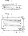
- Figure 1 is a perspective view showing one embodiment of the warming panel to be an object of the present invention
- Figure 2 is an explanatory diagram showing a structure of the outer shell structure
- Figure 3 is a longitudinal cross-sectional view showing a state of setting the outer shell structure in an injection press mold prior to injection of the liquid
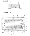
- Figure 4 is an explanatory diagram showing a state of flow of the liquid at the time of its injection
- Figure 5 is an enlarged cross-sectional view taken along a line V-V in Figure 4
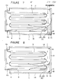
- Figure 6 is an explanatory diagram of a floor warming panel, which shows another embodiment of the warming panel according to the present invention
- Figures 7 and 8 are respectively explanatory diagrams of the floor warming panel, which show still other embodiments of the present invention.
- the floor warming panel (P) as one embodiment of the present invention is in a planar shape, and has such a structure that a heat insulating layer (3) of hard urethane foam, etc. is formed by charging it in a space between a front surface plate (1) made of a sheet metal and a rear surface plate (2) made of a sheet metal or an appropriate heat insulating board.
- FIG. 1 is formed of copper or plastic material, the entire portion of which is embedded in the heat insulating layer (3), except for its connecting ends (4a), as shown in Figure 1.
- Those adjacent corner portions on the outer surface side of the front surface plates (1) are so designed that they can be connected with a triangular connecting plate (5) which covers the two floor warming panels (P) in a manner to be screw-fitted from the outer surface sides.
- This screw-fitting of the connecting plate (5) is done by screwing of a tightening screw (7) into a studded nut (6), as one example of the fixed part as embedded in the interior of the front surface plate.
- a flange (lA) is formed by bending the surrounding edges of the front surface plate (1) at the right angle, the adjacent ends (lC) of which are merely abutted.
- the floor warming panel (P) as mentioned above is placed on the floor surface of a building in such a manner that the front surface plate (1) may face upward. And then, by circulating a heat medium such as, for example, a high temperature water into the interior of the conduit tube (4) from one end of it, the heat of the warm water is discharged through the front surface plate (1) to effect the floor warming.
- a heat medium such as, for example, a high temperature water
- the floor warming panel (P) of such construction is generally manufactured by arranging and fixing the conduit tube (4) in a tortuous form on the inner surface side of the front surface plate (1), followed by fitting thereto the rear surface plate (2) to form an outer shell structure (8) of a hollow planar construction as a whole, then injecting liquid of the heat insulating material such as urethane foam, etc. at a high speed into the interior space of the outer shell structure (8) to fill by its foaming action the space between the front surface plate (1) and the rear surface plate (2), thereby forming the stabilized heat insulating layer (3) of urethane foam, etc. within the outer shell structure (8) enclosing the conduit tube (4).
- the panel as one example of application of the present invention is basically manufactured by following the above-described production steps.
- the conduit tube (4) is secured in such tortuous form by use of a fixing means such as aluminum tape (9) on the inner surface side of the front surface plate (1) with the flanges (lA), on which the rear surface plate (2) is to be abutted, being formed by integrally bending its surrounding edge portions from the lateral side, and then the stud nut (6) to be a counter-part of the tightening screw (7) to be screwed in for fixing the triangular connecting plate (5) is fitted into a polygonal hole (10) formed in the corner part at two portions of the front surface plate except for the lead-out portions of the connecting end (4a) of the conduit tube (4), and adapted to the shape of the stud nut (6) such as hexagonal shape, etc., the nut being fitted thereinto from the back surface side and fixed tentatively.
- a fixing means such as aluminum tape (9) on the inner surface side of the front surface plate (1) with
- the rear surface plate (2) is mounted on the flanges (lA) at the back of this front surface plate (1) in registration therewith, while maintaining an appropriate assembling relationship between the front surface plate (1) and the rear surface plate (2) by means of a fixing tape (11), etc., thereby forming the outer shell structure (8) of a hollow planar construction with the conduit tube (4) being provided in its interior.
- the outer shell structure (8) has a charging port (12) formed in advance at its one part near the corner where the connecting plate (5) is attached to one surface side thereof, and has the buffer material (13) made of soft urethane foam, etc. mounted at its another corner opposite to the charging port in a manner to cover the front side of the stud nut (6) which has been tentatively secured in the polygonal hole (10), i.e., the side of the charging port (12).
- the floor warming panel (P) can be completed, as shown in Figure 3, by setting the outer shell structure (8) in a space between the upper mold (14) and the lower mold (15) of the press mold for injecting the insulating material with the rear surface plate (2) facing upward and with spacers (16) of aluminum or iron being positioned between the upper and lower molds, then lowering the upper mold (14) in the direction shown by an arrow mark, followed by connecting an injection nozzle (17) of a high pressure injector (not shown in the drawing) with the charging port (12) in a state of the entire circumference and both upper and lower surfaces of the outer shell structure being confined in the press mold, and injecting the liquid of hard urethane foam, etc.
- the pressure at the time of the 'foaming is 2 kg/cm 2 in this embodiment.
- the buffer material (13) is provided at the portion where the liquid is impinged, whereby, even if any connected portions such as, for example, an abutting portion (lB) between the flanges (lA) and (lA) of the front surface plate (1), or the stud nut (6), are positioned at that portion, they will not be deformed, damaged, or displaced by collision of the liquid thereto, hence there is substantially no possibility of disqualified product being yielded by such cause.
- any connected portions such as, for example, an abutting portion (lB) between the flanges (lA) and (lA) of the front surface plate (1), or the stud nut (6)
- the buffer material (13) absorbs the liquid and does not interfere with the circumventing liquid, the formation of the heat insulating layer (3) in the outer shell structure (8) can be effected as has been done so far, whereby the buffer material (13) and the heat insulating layer (3) are ultimately brought to an integral and inseparable whole.
- FIG. 6 illustrates another embodiment to attain the above-mentioned second object of the present invention.
- the outer shell structure (not shown in the drawing) same as that of the preceding embodiment has the charging port (12) formed in the vicinity of the corner part where the connecting plate is mounted to one side part thereof, and the flow guide plate (20) in a curved form to direct the liquid injected from the charging port (12) to the center of the outer shell structure interior as well as to the diagonal direction of the charging port (12) thereof is fixed by means of a tape, etc. at the middle part between the charging port (12) and the corner part opposite to it in a manner to be aslant with respect to the inner surface of the outer shell structure.
- the flow guide plate (20) is made of a material such as, for example, metal and plastic materials.
- the other construction than that as mentioned above is identical with that shown in Figures 1 through 5 hence the explanations thereof will be dispensed with.
- the warming panel (P) can be completed in the same manner as the embodiment shown in Figures 1 through 5 by connecting the injection nozzle (17) of the high pressure injector (not shown in the drawing) with the charging port (12), and injecting the liquid of urethane foam, etc. at a high speed into the outer shell structure to cause it to foam in its interior to thereby form the integral heat insulating layer (3).
- the injection nozzle (17) of the high pressure injector not shown in the drawing
- the charging port (12) injecting the liquid of urethane foam, etc.
- the liquid of urethane foam, etc. at a high speed into the outer shell structure to cause it to foam in its interior to thereby form the integral heat insulating layer (3).
- the heat insulating layer (3) there is applied a fairly vigorous impact force onto the portion where the liquid immediately after its injection is impinged.
- the portion where the liquid is impinged has the flow guide plate (20), and no connected portions or stud nut (6) of the outer shell structure are provided, not only there is no possibility of such connected portions or stud nut being deformed, damaged, or displaced by collision thereto of the liquid, but also the flowing direction of the injected liquid within the outer shell structure is restricted by the flow guide plate (20) and there is no possibility of the liquid moving around the circumferential portion of the outer shell structure.
- unfilled portion i.e., mold cavity
- the center part of the outer shell structure i.e., the front surface plate (1) which is structurally unstable, or, even if such mold cavity is created, it will be formed at a particular location (21) to the side of the end surface of the outer shell structure where no structural problem is present. Accordingly, a rate of yield of disqualified product due to the abovementioned cause becomes remarkably reduced.
- the first embodiment of the present invention provides the buffer material to prevent the liquid from directly impinging on the fixed parts or connected portions on the outer shell structure in a manner to be opposite to the charging port of the liquid of the heat insulating material, whereby displacement of the fixed parts, or damage or deformation of the connected portions to be brought about by collision thereto of the liquid with its injection under a high pressure can be well prevented, and the production of disqualified product can be effectively reduced.
- the second embodiment of the present invention provides, in the outer shell structure, the flow guide plate which restrains the flowing direction of the injected liquid at a high speed in such a manner that the ultimate charging portion thereof may come to a predetermined end surface side of the outer shell structure.
- FIGS 7 and 8 illustrate still other embodiments of the present invention. These two embodiments respectively adopt the concept of the afore-described first and second embodiments of the present invention.
- the characteristic of these two embodiments are such that, in order to prevent the charging liquid from directly impinging on the stud nut (6) as one of the fixed parts and the connected portion (lB), etc. as well as to restrain the flowing direction of the charging liquid, the buffer material (13) as mentioned in reference to Figures 1 through 6 is overlayed on one side surface of the flow guide plate (20) to thereby form an integral guide member (30).
- the buffer material (13) and the flow guide plate (20) are not necessarily made integral.
Landscapes
- Engineering & Computer Science (AREA)
- General Engineering & Computer Science (AREA)
- Chemical & Material Sciences (AREA)
- Thermal Sciences (AREA)
- Combustion & Propulsion (AREA)
- Mechanical Engineering (AREA)
- Physics & Mathematics (AREA)
- Casting Or Compression Moulding Of Plastics Or The Like (AREA)
- Steam Or Hot-Water Central Heating Systems (AREA)
- Building Environments (AREA)
- Thermotherapy And Cooling Therapy Devices (AREA)
- Mattresses And Other Support Structures For Chairs And Beds (AREA)
- Filling Or Discharging Of Gas Storage Vessels (AREA)
Applications Claiming Priority (4)
| Application Number | Priority Date | Filing Date | Title |
|---|---|---|---|
| JP58034134A JPS59158919A (ja) | 1983-03-02 | 1983-03-02 | 床暖房パネルの製造方法 |
| JP58034133A JPS59158918A (ja) | 1983-03-02 | 1983-03-02 | 床暖房パネルの製造方法 |
| JP34134/83 | 1983-03-02 | ||
| JP34133/83 | 1983-03-02 |
Publications (3)
| Publication Number | Publication Date |
|---|---|
| EP0140974A1 true EP0140974A1 (de) | 1985-05-15 |
| EP0140974A4 EP0140974A4 (de) | 1986-05-12 |
| EP0140974B1 EP0140974B1 (de) | 1988-07-27 |
Family
ID=26372921
Family Applications (1)
| Application Number | Title | Priority Date | Filing Date |
|---|---|---|---|
| EP84901007A Expired EP0140974B1 (de) | 1983-03-02 | 1984-03-02 | Heizungspaneel |
Country Status (5)
| Country | Link |
|---|---|
| US (1) | US4723598A (de) |
| EP (1) | EP0140974B1 (de) |
| DE (1) | DE3473033D1 (de) |
| FI (1) | FI81902C (de) |
| WO (1) | WO1984003551A1 (de) |
Cited By (4)
| Publication number | Priority date | Publication date | Assignee | Title |
|---|---|---|---|---|
| GB2248420A (en) * | 1990-10-04 | 1992-04-08 | Ford Motor Co | Injecting plastics foam within an outer cover having an interior structural frame |
| EP0592159A1 (de) * | 1992-10-05 | 1994-04-13 | Rex Anthony Ingram | Heiz-oder Kühlanlage |
| GB2279734A (en) * | 1993-07-06 | 1995-01-11 | Mtu Muenchen Gmbh | Cooling structure for a wall of a propulsion plant |
| WO2015177358A1 (de) * | 2014-05-23 | 2015-11-26 | BARONIN VON DER ROPP, Freya Angela | Temperierelement |
Families Citing this family (16)
| Publication number | Priority date | Publication date | Assignee | Title |
|---|---|---|---|---|
| DE4132870C2 (de) * | 1991-10-03 | 1995-05-11 | Klaus Schlenkermann | Wandheizkörper |
| US6092587A (en) * | 1992-10-05 | 2000-07-25 | Ingram; Rex Anthony | Heating/cooling systems |
| US5595171A (en) * | 1993-11-29 | 1997-01-21 | Makin; Colin | Apparatus for heating concrete |
| US5788152A (en) * | 1995-03-15 | 1998-08-04 | Alsberg; Terry Wayne W. | Floor heating system |
| DE29517701U1 (de) * | 1995-11-08 | 1996-01-04 | Kühling & Hauers Schwimmbadtechnik GmbH, 30916 Isernhagen | Plattenförmiges Wärmestrahlungselement |
| DE19623245C2 (de) * | 1996-05-30 | 1999-07-29 | Herbst Donald | Wärmetauscher |
| PT1004827E (pt) * | 1998-11-23 | 2002-11-29 | Plan Holding Gmbh | Painel radiante pre-fabricado modular e ato-suportado processos para a sua producao e superficie radiante obtida com o mesmos |
| DE10016091C5 (de) * | 2000-03-31 | 2010-03-04 | Ltg Aktiengesellschaft | Hohlwand |
| US7690170B2 (en) * | 2004-05-07 | 2010-04-06 | Cable Bridge Enterprises Limited | Homes and home construction |
| WO2007033255A2 (en) * | 2005-09-14 | 2007-03-22 | Uponor, Inc. | Radiant heating system and method |
| KR200432475Y1 (ko) * | 2006-09-20 | 2006-12-04 | 두 년 김 | 난방용 가장자리 패널 |
| SE532498C2 (sv) * | 2007-06-11 | 2010-02-09 | Leif Anders Jilken | Anordning vid en energiförmedlare |
| IT1396502B1 (it) * | 2009-11-25 | 2012-12-14 | Five T Srl | Dispositivo per la giunzione di elementi profilati in linea, a squadra o ad angolo |
| CZ303841B6 (cs) * | 2012-02-14 | 2013-05-22 | Vysoké ucení technické v Brne | Tepelne akumulacní modul se systémem kapilárních rohozí a sestava z techto modulu |
| EP3112549A1 (de) * | 2015-07-01 | 2017-01-04 | KEOKI Company SA | Baupaneel zur erstellung von heizwänden und/oder kühlwänden von gebäuden |
| KR102046630B1 (ko) * | 2018-02-13 | 2019-11-19 | (주)제이앤씨트레이딩 | 조립식 온수 매트 |
Family Cites Families (31)
| Publication number | Priority date | Publication date | Assignee | Title |
|---|---|---|---|---|
| US2653139A (en) * | 1950-05-20 | 1953-09-22 | Westinghouse Electric Corp | In-place expanded cellular resinous bodies and processes for producing them from phenol-aldehyde resins with the aid of a peroxide |
| US2983963A (en) * | 1955-07-20 | 1961-05-16 | Electrolux Ab | Method of making multidensity expanded plastic body |
| US2993233A (en) * | 1956-03-27 | 1961-07-25 | Bayer Ag | Apparatus and process for making composite structures |
| US3081488A (en) * | 1960-02-17 | 1963-03-19 | Casavan Ind Inc | Mold form for fabricating modules |
| US3221085A (en) * | 1961-08-28 | 1965-11-30 | Gen Motors Corp | Process of making an insulated cabinet |
| US3137744A (en) * | 1961-09-19 | 1964-06-16 | Gen Motors Corp | Refrigerating apparatus |
| US3249486A (en) * | 1962-06-29 | 1966-05-03 | Nat Gypsum Co | Method and apparatus for producing foamed synthetic resins |
| US3132382A (en) * | 1962-09-13 | 1964-05-12 | Gen Electric | Resin foam insulated cabinet |
| US3209056A (en) * | 1962-10-30 | 1965-09-28 | Gen Motors Corp | Method of insulating refrigerator cabinets and other insulation spaces |
| GB1118581A (en) * | 1965-04-01 | 1968-07-03 | Gen Motors Ltd | Inter-wall foamed thermal insulation |
| US3383440A (en) * | 1965-04-14 | 1968-05-14 | American Motors Corp | Foam pour method |
| US3440308A (en) * | 1965-09-09 | 1969-04-22 | Gen Electric | Method of making a refrigerator cabinet assembly |
| US3444280A (en) * | 1966-11-21 | 1969-05-13 | Westinghouse Electric Corp | Method of applying foam insulation to a refrigerator cabinet |
| DE2020205A1 (de) * | 1970-04-25 | 1971-11-11 | Bauknecht Gmbh G | Verfahren zur Herstellung eines Korpus eines Kuehlschrankes od.dgl. |
| JPS4866309U (de) * | 1971-11-25 | 1973-08-23 | ||
| US3904721A (en) * | 1973-06-04 | 1975-09-09 | Franklin Mfg Co | Method of assembling a refrigeration cabinet |
| JPS5038159A (de) * | 1973-08-08 | 1975-04-09 | ||
| JPS5522395Y2 (de) * | 1975-05-30 | 1980-05-28 | ||
| JPS5215163A (en) * | 1975-07-28 | 1977-02-04 | Matsushita Electric Ind Co Ltd | Heat generating panel |
| US4102721A (en) * | 1976-10-13 | 1978-07-25 | Minnesota Mining And Manufacturing Company | Barrier tape construction |
| US4212348A (en) * | 1977-04-04 | 1980-07-15 | Toshiyuki Kobayashi | Heat-radiating floor board |
| US4118451A (en) * | 1977-05-02 | 1978-10-03 | Whirlpool Corporation | Method of controlling foaming of cabinet insulation |
| JPS5749737Y2 (de) * | 1978-02-14 | 1982-10-30 | ||
| JPS54128856A (en) * | 1978-03-29 | 1979-10-05 | Hitachi Ltd | Manufacturing process of heat-insulating box |
| JPS55107434A (en) * | 1979-02-10 | 1980-08-18 | Toyo Sash Kk | Manufacturing method of panel for construction use |
| US4240999A (en) * | 1979-04-09 | 1980-12-23 | Igloo Corporation | Method for introducing multi-component foam reactants into mold form involving the use of a foaming spacer |
| US4306616A (en) * | 1980-02-04 | 1981-12-22 | Duke Manufacturing Co. | Refrigerated shelf for a food display counter |
| JPS608407B2 (ja) * | 1980-05-09 | 1985-03-02 | 三菱電機株式会社 | 床暖房装置 |
| JPS56157735A (en) * | 1980-05-09 | 1981-12-05 | Mitsubishi Electric Corp | Floor heater and its manufacture |
| JPS576734A (en) * | 1980-06-16 | 1982-01-13 | Sanyo Electric Co Ltd | Manufacture of heat-insulated box |
| JPS578129A (en) * | 1980-06-17 | 1982-01-16 | Sanyo Electric Co Ltd | Manufacture of heat insulating box |
-
1984
- 1984-03-02 EP EP84901007A patent/EP0140974B1/de not_active Expired
- 1984-03-02 DE DE8484901007T patent/DE3473033D1/de not_active Expired
- 1984-03-02 US US06/846,490 patent/US4723598A/en not_active Expired - Fee Related
- 1984-03-02 WO PCT/JP1984/000077 patent/WO1984003551A1/ja not_active Ceased
- 1984-11-01 FI FI844294A patent/FI81902C/fi not_active IP Right Cessation
Cited By (5)
| Publication number | Priority date | Publication date | Assignee | Title |
|---|---|---|---|---|
| GB2248420A (en) * | 1990-10-04 | 1992-04-08 | Ford Motor Co | Injecting plastics foam within an outer cover having an interior structural frame |
| EP0592159A1 (de) * | 1992-10-05 | 1994-04-13 | Rex Anthony Ingram | Heiz-oder Kühlanlage |
| US5497826A (en) * | 1992-10-05 | 1996-03-12 | Ingram; Rex A. | Heating/cooling systems |
| GB2279734A (en) * | 1993-07-06 | 1995-01-11 | Mtu Muenchen Gmbh | Cooling structure for a wall of a propulsion plant |
| WO2015177358A1 (de) * | 2014-05-23 | 2015-11-26 | BARONIN VON DER ROPP, Freya Angela | Temperierelement |
Also Published As
| Publication number | Publication date |
|---|---|
| EP0140974A4 (de) | 1986-05-12 |
| US4723598A (en) | 1988-02-09 |
| FI81902B (fi) | 1990-08-31 |
| DE3473033D1 (en) | 1988-09-01 |
| FI81902C (fi) | 1990-12-10 |
| EP0140974B1 (de) | 1988-07-27 |
| FI844294L (fi) | 1984-11-01 |
| FI844294A0 (fi) | 1984-11-01 |
| WO1984003551A1 (fr) | 1984-09-13 |
Similar Documents
| Publication | Publication Date | Title |
|---|---|---|
| EP0140974B1 (de) | Heizungspaneel | |
| JP6212322B2 (ja) | 断熱パネル | |
| US20180073798A1 (en) | Refrigeration device with reinforced housing | |
| JP3394524B2 (ja) | 冷蔵庫の扉及び冷蔵庫の扉の製造方法 | |
| JP2006162144A (ja) | 冷蔵庫 | |
| JP3164842B2 (ja) | 断熱箱体 | |
| JP2517084B2 (ja) | 断熱箱体 | |
| US4640432A (en) | Refrigeration apparatus cabinet construction utilizing prepainted steel panels | |
| JPH0814457B2 (ja) | 断熱箱体 | |
| JPS6328398Y2 (de) | ||
| KR100398672B1 (ko) | 조립식 단열판넬의 상단부 마감구조 | |
| KR100252160B1 (ko) | 냉장고의 캐비넷 조립 구조 | |
| JP2562077Y2 (ja) | 断熱箱体 | |
| JPS5811909Y2 (ja) | 断熱ドア | |
| JPH0347194Y2 (de) | ||
| JPH0413082A (ja) | 断熱箱体 | |
| JPS5934869Y2 (ja) | 冷蔵庫等の断熱箱体 | |
| EP4227584A1 (de) | Schutzgehäuse für das gerät und wassererhitzer mit einem solchen schutzgehäuse | |
| NO160233B (no) | Varmepanel. | |
| JPS60228882A (ja) | 断熱方式 | |
| JPS5856544Y2 (ja) | 冷蔵庫の扉体 | |
| JPH06123546A (ja) | 冷蔵庫の扉装置 | |
| JPS6326700Y2 (de) | ||
| KR950007297Y1 (ko) | 냉장고 | |
| JPS6219672A (ja) | 断熱扉の製造方法 |
Legal Events
| Date | Code | Title | Description |
|---|---|---|---|
| PUAI | Public reference made under article 153(3) epc to a published international application that has entered the european phase |
Free format text: ORIGINAL CODE: 0009012 |
|
| AK | Designated contracting states |
Designated state(s): DE FR GB |
|
| 17P | Request for examination filed |
Effective date: 19850306 |
|
| A4 | Supplementary search report drawn up and despatched |
Effective date: 19860512 |
|
| 17Q | First examination report despatched |
Effective date: 19870312 |
|
| GRAA | (expected) grant |
Free format text: ORIGINAL CODE: 0009210 |
|
| AK | Designated contracting states |
Kind code of ref document: B1 Designated state(s): DE FR GB |
|
| REF | Corresponds to: |
Ref document number: 3473033 Country of ref document: DE Date of ref document: 19880901 |
|
| ET | Fr: translation filed | ||
| PLBE | No opposition filed within time limit |
Free format text: ORIGINAL CODE: 0009261 |
|
| STAA | Information on the status of an ep patent application or granted ep patent |
Free format text: STATUS: NO OPPOSITION FILED WITHIN TIME LIMIT |
|
| 26N | No opposition filed | ||
| PGFP | Annual fee paid to national office [announced via postgrant information from national office to epo] |
Ref country code: GB Payment date: 19920221 Year of fee payment: 9 |
|
| PGFP | Annual fee paid to national office [announced via postgrant information from national office to epo] |
Ref country code: FR Payment date: 19920310 Year of fee payment: 9 |
|
| PGFP | Annual fee paid to national office [announced via postgrant information from national office to epo] |
Ref country code: DE Payment date: 19920331 Year of fee payment: 9 |
|
| PG25 | Lapsed in a contracting state [announced via postgrant information from national office to epo] |
Ref country code: GB Effective date: 19930302 |
|
| GBPC | Gb: european patent ceased through non-payment of renewal fee |
Effective date: 19930302 |
|
| PG25 | Lapsed in a contracting state [announced via postgrant information from national office to epo] |
Ref country code: FR Effective date: 19931130 |
|
| PG25 | Lapsed in a contracting state [announced via postgrant information from national office to epo] |
Ref country code: DE Effective date: 19931201 |
|
| REG | Reference to a national code |
Ref country code: FR Ref legal event code: ST |