EP0140397B1 - Dispositif de dénudage pour câble coaxial - Google Patents
Dispositif de dénudage pour câble coaxial Download PDFInfo
- Publication number
- EP0140397B1 EP0140397B1 EP84201056A EP84201056A EP0140397B1 EP 0140397 B1 EP0140397 B1 EP 0140397B1 EP 84201056 A EP84201056 A EP 84201056A EP 84201056 A EP84201056 A EP 84201056A EP 0140397 B1 EP0140397 B1 EP 0140397B1
- Authority
- EP
- European Patent Office
- Prior art keywords
- knifeholder
- cable
- guide
- stripping device
- cutting means
- Prior art date
- Legal status (The legal status is an assumption and is not a legal conclusion. Google has not performed a legal analysis and makes no representation as to the accuracy of the status listed.)
- Expired - Lifetime
Links
- 238000009413 insulation Methods 0.000 claims description 18
- 238000006073 displacement reaction Methods 0.000 claims 1
- 238000007373 indentation Methods 0.000 claims 1
- 230000033001 locomotion Effects 0.000 description 11
- 210000000078 claw Anatomy 0.000 description 6
- 239000000463 material Substances 0.000 description 5
- 230000000149 penetrating effect Effects 0.000 description 4
- 238000003801 milling Methods 0.000 description 3
- 230000001419 dependent effect Effects 0.000 description 2
- 238000000034 method Methods 0.000 description 2
- 238000009825 accumulation Methods 0.000 description 1
- 238000013459 approach Methods 0.000 description 1
- 239000000969 carrier Substances 0.000 description 1
- 238000013461 design Methods 0.000 description 1
- 238000011161 development Methods 0.000 description 1
- 230000018109 developmental process Effects 0.000 description 1
- 238000012986 modification Methods 0.000 description 1
- 230000004048 modification Effects 0.000 description 1
- 239000004033 plastic Substances 0.000 description 1
- 230000001681 protective effect Effects 0.000 description 1
Images


Classifications
-
- H—ELECTRICITY
- H02—GENERATION; CONVERSION OR DISTRIBUTION OF ELECTRIC POWER
- H02G—INSTALLATION OF ELECTRIC CABLES OR LINES, OR OF COMBINED OPTICAL AND ELECTRIC CABLES OR LINES
- H02G1/00—Methods or apparatus specially adapted for installing, maintaining, repairing or dismantling electric cables or lines
- H02G1/12—Methods or apparatus specially adapted for installing, maintaining, repairing or dismantling electric cables or lines for removing insulation or armouring from cables, e.g. from the end thereof
- H02G1/1202—Methods or apparatus specially adapted for installing, maintaining, repairing or dismantling electric cables or lines for removing insulation or armouring from cables, e.g. from the end thereof by cutting and withdrawing insulation
- H02G1/1204—Hand-held tools
- H02G1/1221—Hand-held tools the cutting element rotating about the wire or cable
- H02G1/1224—Hand-held tools the cutting element rotating about the wire or cable making a transverse cut
Definitions
- the invention relates to a stripping device for coaxial cables of the type mentioned in the preamble of claim 1, which among other things. a guideway for an end piece of the cable to be stripped and at least two knives which can be rotated about this end piece and which initially only make a short incision in the cable, which is then extended to the entire circumference of the cable by mutual rotary movement.
- a coaxial cable has an inner conductive core, an inner insulation sheath surrounding it, an outer conductive layer (shielding) surrounding it and finally an outer insulation layer surrounding the outer conductive layer.
- a cut closest to the cable end is made which extends deepest and cuts through all of the layers mentioned up to the conductive core, and at a certain distance from the first cut a second cut is made which only cuts through the outer insulation layer, so that after removing the separated insulation part, the outer conductive layer is exposed. If necessary, a further incision can be made between the first and the second incision, which cuts through the outer insulation layer and the outer conductive layer, so that after removal of the separated parts, a portion of the inner insulation layer is exposed.
- US Pat. No. 3,161,088 describes a stripping device for coaxial cables which has an elongated, tubular handle part with a through opening or bore for the treated cable, and a coaxially and fully rotatably connected, elongated tubular guideway part with an opening or bore , which forms a guideway for a cable protruding from the handle part. Both parts are approximately the same size and of the same design, and are adapted to be gripped with one hand and to be twisted.
- Axial slots connected to the openings are arranged in both parts.
- a simple locking arrangement for non-rotatably holding the inserted cable is accommodated in the slot in the handle part, which consists of an articulated lever with a profiled foot part in the region of the articulation point. When the handle part is gripped with one hand, the lever is pressed into the slot and its foot part acts on the cable.
- a knife carrier is arranged in the form of a lever articulated at its second end remote from the handle part to the second end of the guideway part distant from the handle part, in which knife members of different lengths are arranged at mutual intervals, the longest closest to the articulation point. Similar to the locking lever in the 'handle part, the knife carrier lever is gradually pushed into its slot by the other hand when the guideway part is grasped, the individual knives, beginning with the one closest to the articulation point, penetrating into the outer layers of the coaxial cable.
- the force with which the knife carrier lever is pressed in can in no way be made dependent on the speed at which one wishes the knife to penetrate, but this force is primarily dependent on how tightly the guide part is gripped must be in order to be able to be rotated relative to the handle part against the resistance of the penetrating knife.
- the knife carrier lever equipped with knives comes to lie close to the cable in its end position in the narrow hole that is closed on all sides in this state, which leads to the accumulation of insulation residues etc. can lead.
- a stripping device is known from US Pat. No. 3,688,404, in which the guideway part runs at right angles to an elongated handle part.
- the device has a single knife, which is pivotally arranged in a knife holder, which is supported in an adjustable position by a crank arm.
- the device cannot be used for stripping coaxial cables.
- the present invention has for its object to provide a device of the type mentioned in the preamble of claim 1, in which, while maintaining the possibility of eliminating the risk of jamming mentioned at the outset, the carrying out of the rotary movement of the guideway member is considerably facilitated and also the regulation of the knife engagement by the Power to drive the rotary motion is made independent.
- a larger free space between the knife carrier and the cable and the exact working position of the knife carrier should also be able to be selected when the cable is introduced into the guideway member.
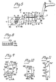
- a coaxial cable 30 is stripped in such a way that at a preselected distance A from the cable end Zin in level I a first incision to the conductive core 34 of the cable, and at an axial distance B (FIG. 1 a) or B + B '(FIG. 1 b) thereof, in plane II, a second incision merely through the outer insulation layer 31, and optionally (FIG. 1 b) in plane 111, a third incision up to the inner insulation layer 33.
- The. Separated parts of the insulation are then stripped from the cable. In the rather short section, when all the knives engage simultaneously, material stalls, which in particular brakes the deepest penetrating knife in the plane during the subsequent rotary movement.
- the device 10 has an elongated handle part 11 on which an axial through opening 11 'is provided and which is possibly corrugated on the surface, which is not shown.
- a lever 14 protruding somewhat from the surface of the handle part is arranged in an axially extending elongated slot 11 ".
- the lever 14 is conveniently mounted at one end at the end which is farther from the guideway member, in the handle part 11 at 14 'and is provided at the opposite end with a braking element in the form of a rubber block 14a
- the lever 14 is pressed in and the block 14a is pressed against a coaxial cable 30 inserted into the opening 11 ', whereby the cable is rotatably connected to the handle part 11. This position is shown in Fig. 2.
- the guide track member 12 is in the section protruding from the handle part 11 along a preselected distance up to a certain part of its cross section, e.g. about half, removed, whereby the axial opening 12 'is formed into a trough or support bed forming the actual guideway 12 "for a corresponding end section of the coaxial cable 30 comprising the distances A + B or A + B + B'.
- An adjustable end stop screw 15 enables precise adjustment of the distance A.
- a lever arm 16 projecting essentially at right angles to the guideway 12 is pivotably mounted in the guideway member 12 at 16 '.
- the lever arm 16 is provided with and forms a rotatable crank handle 16a together with this a crank member.
- an elongated knife carrier 17 which runs at a distance along the guideway 12 ′′ and in the operative position essentially parallel to it, is limitedly rotatable by means of a bearing pin 17 ′.
- the knife carrier 17 can be e.g. from a control knob 17a arranged at the projecting free end of the bearing pin 17 '.
- Cylindrical knife carriers 17 are individual knives 21 (for the incision at 1), 22 (for the incision at II ') and 23 (for the incision at II) inserted and by means of screws such as 21', 22 'in the selected position (lengthwise) secured.
- the arrangement is such that the knives 22 and 23 (the knife 23 is entirely covered by the knife 22 in FIG. 2 and is therefore not visible) assume a different angular position in the cross-sectional direction than the knife 21.
- the knife carrier 17 is either brought into a first end position for the engagement of the knife 21 only, or into a second end position for the engagement of the knife 22 and a possible third knife 23.
- a stop is provided for fixing its working position according to FIG. 2, in the example shown an adjustable stop in the form of an adjusting screw 17b, the end of which comes to rest on the non-worn part of the guideway member can.
- the rod-shaped knives 21-23 can advantageously have the known shape of a thin biconvex lens in cross section, as indicated at f. Furthermore, a depression 12a can be arranged in the guideway 12 "at the location of the incision in the plane I or S ⁇ S. Both the profile shape of the knife and the depression serve to further reduce the friction of the knife against the insulation layers , wherein the recess 12a is provided for receiving a local bulge of the cut insulation layer.
- the device is used in the following ways:
- the adjusting screw 15 is set for the desired length A and the lever arm 16 is pivoted in the direction of the arrow P, as a result of which the knife carrier 17 is brought into a rest position in which the guideway 12 "is free of the knives 21-23.
- the adjusting button can 17a are actuated in such a way that the knife carrier 17 assumes a middle non-engagement position (see FIG. 4) in which none of the knives engages even if the knife carrier is in the working position shown in Fig. 2.
- the middle non-engagement position of the knife carrier 17 is through a spring-loaded snap ball 18 'is fixed, which is arranged in the foot part of the lever arm 16 and can snap into a corresponding recess in the bearing pin 17' of the knife carrier 17.
- the handle part 11 is firmly gripped by the user with one hand, the lever 14 being pressed down and the rubber block 14a being pressed onto the inserted cable 30. Then the button 17a is actuated such that the knife carrier 17 is pivoted in such a way that the knife 21 penetrates the cable 30. This movement removes the knives 22 and 23 from the cable even further.
- the previously limited incision of the knife 21 is made over the entire circumference of the cable 30 expanded, the insulation layers are in no way hindered to move freely in the axial direction of the cable (to the left in Fig. 2).
- the guideway 12 "thus rotates around the stationary cable 30 which is pressed against it by the engaging knife.
- the guideway can expediently be provided with a friction-reducing inner lining, for example made of plastic known for this purpose (see Fig. 11).
- the knife carrier 17 is then brought into the second end position, where the knives 22 and 23 make incisions, the knife 21 having been removed from the cable. During at least one new full revolution, the incisions of these knives are also extended over the entire circumference of the cable 30. Then the knife carrier 17 is brought into the rest position by pivoting the lever arm 16 in the direction of the arrow P and / or is turned into the non-engaged position by pressing the button 17a and the cable 30 is pulled out of the device (to the left in FIG. 2). The knife carrier can possibly remain in the working and engagement position and then when the cable is pulled out the separated parts are held and stripped by the engaging knives 22, 23.
- Knits 210 and 220 have circular-shaped cutting edges 210 'and 220' which engage the cable 30 from opposite sides in the same way as the knives 21, 22, and their end tips 210 ", 220" when they are brought into engagement with circular-shaped paths Mouth N describe the same way as the tips of knives 21 and 22 in Fig. 3.
- the tilting movement of the knife holder 17 about the pivot point 16 'in FIG. 2 can also be replaced by a straight-line approach movement of the knife holder 17 which is parallel to it. Such a movement can, however, also be completely omitted, in that only the middle non-engagement position (e.g. according to FIG. 4) of the knife holder is used to insert the cable into the device.
- a device 10 'of this type is shown in FIG. 5.
- the knife carrier 17 is rotatably supported on both sides in bearing blocks 160, 162 to a predetermined limited extent, and runs parallel to the guideway 12 ".
- the handle 16a is arranged on a type 161 which, like the button 17a according to FIG
- the handle 16a When the handle 16a is actuated to rotate, for example clockwise, the knife carrier 17 is first brought into its end position provided for the full engagement of the knife 21 until the pin 18 (FIG. 2) stops at one end of the circular-arc-shaped milling, and then the entire part 12 is rotated, after at least one full revolution, the handle 16a is actuated to rotate in the opposite direction and the process is repeated for the knives 22 and 23 (after the pin 18 has reached the opposite end of the arc-shaped cutout).
- the aforementioned snap-in arrangement is also de r spring-loaded ball 18 'is provided to determine the middle non-engagement position.
- the device 10 has an elongated handle part 111, at one end of which a through opening 111 'is provided transversely to the longitudinal direction of the handle part. Following the through opening 111', a guide track member 112 is rotatably mounted in the handle part 111, which protrudes on one side at right angles from the handle part 111. A guide track 112 'is arranged in the guide track member 112 in a manner similar to the guide track member 12.
- a bow-shaped knife carrier 116 can be pivoted by means of a pin 116' which, like the knife holder 16, also has an outstanding lever arm (not shown) which is provided with a crank handle, a U-shaped spring 116b, the bent legs of which extend on both sides of the knife holder 116, while the web 116b '(FIG. 12) does this Crosses end of the guideway 112 ', d Knife holder in the pivoted rest position shown.
- the locking arrangement in the device 10 "consists of an automatic clamping chuck 300 with three elongated clamping jaws 301, 302, 303.
- a pot-shaped actuating element 310 is rotatably supported with its bottom wall 311 turned outwards. It has a grooved outer side surfaces 312 with a diameter K which is somewhat larger than the width k of the handle member 111, so that parts 312 ', 312' 'of the side surface 312 protrude somewhat laterally from the handle part 111 and can be easily actuated by fingers of the hand by which the handle part 111 has been gripped.
- the handle part 111 In the handle part 111, three pins 313, 314, 315 distributed at 120 ° intervals around the through opening 111 'are firmly anchored.
- the pins 313-315 have a narrower shaft part which is not visible because it is located below the bottom wall 311, and a wider head part located above the bottom wall 311.
- the jaws 301, 302, 303 are freely rotatably supported at one end on the respective shaft part.
- the bottom wall 311 has a circular opening 111'a of the through opening 111 'in the middle and three circular-arc-shaped slots 323, 324, 325 running parallel to the side surface 312 on the periphery, and three radial openings between these slots and the opening 111'a rectilinear slots 333, 334, 335.
- the slots 323-325 have a width which corresponds to the diameter of the shaft parts of the pins 313-315 and is smaller than the diameter of their head parts.
- the actuator 310 is thus held by the pins 313-315 in the handle part 111 with the possibility of rotation to the extent of the length of the slots 323 32325.
- On the clamping jaws 301, 302, 303 projecting engagement pins such as 301a are arranged at a distance from the respective articulation points of the clamping jaws on the pins 313-315.
- the engagement pins 301a etc. engage in the radial slots 333-335 in the bottom wall 311.
- a inside the actuator 310 e.g.
- a protective wall 111 a protruding from the handle part 111 protects the finger (s) acting on the actuating member 312 from sliding into the area of the knife carrier 116.
- the device is used in the following ways:
- the actuating member 312 By accessing at least one of the parts 312 ', 312 "of the side surface 312, when the force of the spring 311c is overcome, the actuating member 312 is rotated in the direction of the arrow R until the pins 313-315 abut the opposite ends of the slots 323-325 as as in Fig. 7. As a result, the jaws 301, 302, 303 are pivoted about the pins 313-315 via the slots 333-335 and the pins, such as 301a, in such a way that they expose the mouth 111'a Through opening 111 'and into the guideway 112 " to the stop at 112 "a. Then the actuator 312 is released, the spring 331c turns it against the direction of the arrow R and the jaws 301-303 enclose the cable and connect it via the pins 313-315 in a rotationally fixed manner to the handle part 111 .
- the user grasps the crank handle and, when the rather weak spring 116 is overcome, pivots the knife carrier 116 in the direction of the arrow T. Pivotal movement in the direction of arrow T is completed when the knife carrier 116 strikes a collar 112a on the guideway member 112. Analogously to the device 10 according to FIG. 2, the insulation parts can move freely in the longitudinal direction of the cable for a time after the first intervention of a knife.
- interchangeable elongate inserts 113a-113c are preferably provided in the form of a tube cut open lengthways for the guideway member 112.
- the inserts have the same outer diameter and different
- a slide 114 is arranged on the outside of the guideway member 112 and has, according to FIG. 12, bent longitudinal edges 114a on the outer end of which a projecting engagement claw 114a ', 114a "is provided. With the longitudinal edges 114a, the carriage 114 is slidably suspended on the longitudinal edges of the guideway member 112, one of the engaging claws 114a ", one of the end edges, 113a", of the inserted inserts, e.g.
- the other engaging claw 114a ' engages in an elongated track 113' spaced from and parallel to the other longitudinal edge 113a 'in the outer surface of the insert.
- the insert is thus located in the guideway member 112 in the oblique position shown in FIG. 11, since both engagement claws 114a ', 114a "are at the same height.
- the inlays are somewhat shorter than the guideway, as can be seen from FIG. 12, and have in the bottom area an opening 113 ′′ engages with a short pin 112b arranged in the bottom area of the guideway member 112.
- the carriage 114 is shorter than the guideway member 112 (see FIG.
Landscapes
- Removal Of Insulation Or Armoring From Wires Or Cables (AREA)
Claims (10)
Applications Claiming Priority (2)
| Application Number | Priority Date | Filing Date | Title |
|---|---|---|---|
| SE8304627 | 1983-08-26 | ||
| SE8304627A SE8304627D0 (sv) | 1983-08-26 | 1983-08-26 | Abisoliergeret fur koaxialkabel |
Publications (3)
| Publication Number | Publication Date |
|---|---|
| EP0140397A2 EP0140397A2 (fr) | 1985-05-08 |
| EP0140397A3 EP0140397A3 (en) | 1986-12-10 |
| EP0140397B1 true EP0140397B1 (fr) | 1990-05-09 |
Family
ID=20352309
Family Applications (1)
| Application Number | Title | Priority Date | Filing Date |
|---|---|---|---|
| EP84201056A Expired - Lifetime EP0140397B1 (fr) | 1983-08-26 | 1984-07-16 | Dispositif de dénudage pour câble coaxial |
Country Status (4)
| Country | Link |
|---|---|
| US (1) | US4616533A (fr) |
| EP (1) | EP0140397B1 (fr) |
| DE (1) | DE3482226D1 (fr) |
| SE (1) | SE8304627D0 (fr) |
Cited By (2)
| Publication number | Priority date | Publication date | Assignee | Title |
|---|---|---|---|---|
| DE102007038626B3 (de) * | 2007-08-16 | 2008-10-09 | Wezag Gmbh Werkzeugfabrik | Zange zum Abisolieren eines Kabels |
| CN107534276A (zh) * | 2015-05-11 | 2018-01-02 | 胡贝尔和茹纳股份公司 | 剥线工具 |
Families Citing this family (5)
| Publication number | Priority date | Publication date | Assignee | Title |
|---|---|---|---|---|
| US4730391A (en) * | 1985-12-23 | 1988-03-15 | Warren & Brown & Staff Pty. Ltd. | Wire stripper |
| AU604664B2 (en) * | 1985-12-23 | 1991-01-03 | Warren & Brown & Staff Pty. Ltd. | Wire stripper |
| US6643448B1 (en) * | 2001-04-13 | 2003-11-04 | Wavesplitter Technologies, Inc. | Optical fiber stripping tool |
| US7316058B2 (en) * | 2005-08-15 | 2008-01-08 | Beam-Chi Jee | Coaxial cable stripper |
| KR102521045B1 (ko) * | 2016-11-23 | 2023-04-11 | 쿠퍼스탠다드오토모티브앤인더스트리얼 주식회사 | 편조기 |
Family Cites Families (5)
| Publication number | Priority date | Publication date | Assignee | Title |
|---|---|---|---|---|
| US2455591A (en) * | 1944-12-04 | 1948-12-07 | William S Lindsay | Insulation cutting tool |
| US3161088A (en) * | 1962-12-04 | 1964-12-15 | Harold J Tolman | Stripper for coaxial cables |
| US3688404A (en) * | 1970-12-29 | 1972-09-05 | Albert G Muller | Insulation cable cutter |
| CH609176A5 (fr) * | 1976-04-26 | 1979-02-15 | Loepfe K Automation Ag | |
| SE460939B (sv) | 1980-08-29 | 1989-12-04 | Ca Weidmueller Gmbh & Co | Verktyg foer avisolering av kabelaendar |
-
1983
- 1983-08-26 SE SE8304627A patent/SE8304627D0/xx unknown
-
1984
- 1984-07-16 DE DE8484201056T patent/DE3482226D1/de not_active Expired - Fee Related
- 1984-07-16 EP EP84201056A patent/EP0140397B1/fr not_active Expired - Lifetime
- 1984-08-01 US US06/636,541 patent/US4616533A/en not_active Expired - Fee Related
Cited By (3)
| Publication number | Priority date | Publication date | Assignee | Title |
|---|---|---|---|---|
| DE102007038626B3 (de) * | 2007-08-16 | 2008-10-09 | Wezag Gmbh Werkzeugfabrik | Zange zum Abisolieren eines Kabels |
| EP2026433A2 (fr) | 2007-08-16 | 2009-02-18 | Wezag GmbH Werkzeugfabrik | Pince destinée à dénuder un câble |
| CN107534276A (zh) * | 2015-05-11 | 2018-01-02 | 胡贝尔和茹纳股份公司 | 剥线工具 |
Also Published As
| Publication number | Publication date |
|---|---|
| US4616533A (en) | 1986-10-14 |
| EP0140397A2 (fr) | 1985-05-08 |
| EP0140397A3 (en) | 1986-12-10 |
| DE3482226D1 (de) | 1990-06-13 |
| SE8304627D0 (sv) | 1983-08-26 |
Similar Documents
| Publication | Publication Date | Title |
|---|---|---|
| DE3214479C2 (de) | Handgerät zum Abschälen der äußeren Mantelschicht elektrischer Leitungen und elektrischer Kabel | |
| DE69104126T2 (de) | Vorrichtung zum Herausschneiden des Afters bei Schlachtgeflügel. | |
| DE69008411T2 (de) | Entmantelungsapparat für Koaxialkabel. | |
| EP0291828B1 (fr) | Pince de préhension pour outils de machine-outil | |
| DE69609852T2 (de) | Allzweckmesser mit klingenmagazin | |
| DE2709910C3 (de) | Abisoliervorrichtung | |
| DE3140193A1 (de) | Werkzeug zum abisolieren von kabeln | |
| DE10242881A1 (de) | Multifunktionale Beschneidmaschine | |
| EP0073534B1 (fr) | Outil pour dénuder des fils électriques | |
| EP0140397B1 (fr) | Dispositif de dénudage pour câble coaxial | |
| DE3136406C2 (fr) | ||
| DE3003649A1 (de) | Vorrichtung zum automatischen positionieren des zu vernaehenden endes schlauchfoermiger, mit einem ferseneinsatz versehener struempfe auf einer pneumatischen wendeeinrichtung, insbesondere an einer maschine zum vernaehen der spitze schlauchfoermiger struempfe | |
| DE1805663C3 (de) | Vorrichtung zur Vorbereitung eines Koaxialkabelendes für die Anbringung eines Koaxialkabelverbinders | |
| DE2715445B2 (de) | Vorrichtung zum Entfernen von Schmutzteilchen von einem Formzylinder einer Rotations-Offsetdruckmaschine | |
| EP0206376A2 (fr) | Dispositif pour dénuder | |
| DE3701810A1 (de) | Elektrisches abisoliergeraet | |
| DE3015606C2 (de) | Vorrichtung zum Entfernen eines Teiles eines Isolationsmantels von Kabeln | |
| DE2848445C2 (de) | Gerät zum Abisolieren von elektrischen Leitern | |
| DE19757934A1 (de) | Trimmvorrichtung für einen Rocksaum | |
| DE102021131694B3 (de) | Kabelentmantelungswerkzeug | |
| EP0461080A1 (fr) | Pince à dénuder | |
| EP0216020A2 (fr) | Dispositif pour déduire un bout d'un câble coaxial | |
| DE1908880A1 (de) | Durch einen Ausloeser betaetigte Schaltvorrichtung mit einer Stelleinrichtung fuer die Bewirkung mehrerer bestimmter Stellungen des Ausloesers | |
| DE10214758A1 (de) | Vorrichtung zum Schneiden von Bodenbelägen | |
| DE19756579C1 (de) | Werkzeug zum maschinellen Abschneiden eines Kunststoffrohrs sowie ein Verfahren und eine Vorrichtung zum Fertigen von Kunststoffrohrabschnitten |
Legal Events
| Date | Code | Title | Description |
|---|---|---|---|
| PUAI | Public reference made under article 153(3) epc to a published international application that has entered the european phase |
Free format text: ORIGINAL CODE: 0009012 |
|
| AK | Designated contracting states |
Designated state(s): CH DE FR GB IT LI SE |
|
| PUAL | Search report despatched |
Free format text: ORIGINAL CODE: 0009013 |
|
| AK | Designated contracting states |
Kind code of ref document: A3 Designated state(s): CH DE FR GB IT LI SE |
|
| 17P | Request for examination filed |
Effective date: 19861124 |
|
| 17Q | First examination report despatched |
Effective date: 19880408 |
|
| ITF | It: translation for a ep patent filed | ||
| GRAA | (expected) grant |
Free format text: ORIGINAL CODE: 0009210 |
|
| AK | Designated contracting states |
Kind code of ref document: B1 Designated state(s): CH DE FR GB IT LI SE |
|
| GBT | Gb: translation of ep patent filed (gb section 77(6)(a)/1977) | ||
| REF | Corresponds to: |
Ref document number: 3482226 Country of ref document: DE Date of ref document: 19900613 |
|
| ET | Fr: translation filed | ||
| ITTA | It: last paid annual fee | ||
| PGFP | Annual fee paid to national office [announced via postgrant information from national office to epo] |
Ref country code: FR Payment date: 19910111 Year of fee payment: 8 |
|
| PLBE | No opposition filed within time limit |
Free format text: ORIGINAL CODE: 0009261 |
|
| STAA | Information on the status of an ep patent application or granted ep patent |
Free format text: STATUS: NO OPPOSITION FILED WITHIN TIME LIMIT |
|
| 26N | No opposition filed | ||
| PGFP | Annual fee paid to national office [announced via postgrant information from national office to epo] |
Ref country code: CH Payment date: 19910514 Year of fee payment: 8 |
|
| PGFP | Annual fee paid to national office [announced via postgrant information from national office to epo] |
Ref country code: DE Payment date: 19910702 Year of fee payment: 8 |
|
| PGFP | Annual fee paid to national office [announced via postgrant information from national office to epo] |
Ref country code: SE Payment date: 19910719 Year of fee payment: 8 |
|
| PGFP | Annual fee paid to national office [announced via postgrant information from national office to epo] |
Ref country code: GB Payment date: 19920706 Year of fee payment: 9 |
|
| PG25 | Lapsed in a contracting state [announced via postgrant information from national office to epo] |
Ref country code: SE Effective date: 19920717 |
|
| PG25 | Lapsed in a contracting state [announced via postgrant information from national office to epo] |
Ref country code: LI Effective date: 19920731 Ref country code: CH Effective date: 19920731 |
|
| PG25 | Lapsed in a contracting state [announced via postgrant information from national office to epo] |
Ref country code: FR Effective date: 19930331 |
|
| REG | Reference to a national code |
Ref country code: CH Ref legal event code: PL |
|
| PG25 | Lapsed in a contracting state [announced via postgrant information from national office to epo] |
Ref country code: DE Effective date: 19930401 |
|
| REG | Reference to a national code |
Ref country code: FR Ref legal event code: ST |
|
| PG25 | Lapsed in a contracting state [announced via postgrant information from national office to epo] |
Ref country code: GB Effective date: 19930716 |
|
| GBPC | Gb: european patent ceased through non-payment of renewal fee |
Effective date: 19930716 |
|
| EUG | Se: european patent has lapsed |
Ref document number: 84201056.3 Effective date: 19930204 |