EP0140275A2 - Handhebel für Eingriffmischventile - Google Patents
Handhebel für Eingriffmischventile Download PDFInfo
- Publication number
- EP0140275A2 EP0140275A2 EP19840112494 EP84112494A EP0140275A2 EP 0140275 A2 EP0140275 A2 EP 0140275A2 EP 19840112494 EP19840112494 EP 19840112494 EP 84112494 A EP84112494 A EP 84112494A EP 0140275 A2 EP0140275 A2 EP 0140275A2
- Authority
- EP
- European Patent Office
- Prior art keywords
- hand lever
- lever
- head housing
- housing
- rotation
- Prior art date
- Legal status (The legal status is an assumption and is not a legal conclusion. Google has not performed a legal analysis and makes no representation as to the accuracy of the status listed.)
- Granted
Links
- 239000000463 material Substances 0.000 claims description 2
- XLYOFNOQVPJJNP-UHFFFAOYSA-N water Substances O XLYOFNOQVPJJNP-UHFFFAOYSA-N 0.000 description 4
- VQKWAUROYFTROF-UHFFFAOYSA-N arc-31 Chemical compound O=C1N(CCN(C)C)C2=C3C=C4OCOC4=CC3=NN=C2C2=C1C=C(OC)C(OC)=C2 VQKWAUROYFTROF-UHFFFAOYSA-N 0.000 description 3
- 210000002105 tongue Anatomy 0.000 description 3
- 238000012423 maintenance Methods 0.000 description 1
- 229910052574 oxide ceramic Inorganic materials 0.000 description 1
Images

Classifications
-
- F—MECHANICAL ENGINEERING; LIGHTING; HEATING; WEAPONS; BLASTING
- F16—ENGINEERING ELEMENTS AND UNITS; GENERAL MEASURES FOR PRODUCING AND MAINTAINING EFFECTIVE FUNCTIONING OF MACHINES OR INSTALLATIONS; THERMAL INSULATION IN GENERAL
- F16K—VALVES; TAPS; COCKS; ACTUATING-FLOATS; DEVICES FOR VENTING OR AERATING
- F16K31/00—Actuating devices; Operating means; Releasing devices
- F16K31/44—Mechanical actuating means
- F16K31/60—Handles
- F16K31/605—Handles for single handle mixing valves
-
- Y—GENERAL TAGGING OF NEW TECHNOLOGICAL DEVELOPMENTS; GENERAL TAGGING OF CROSS-SECTIONAL TECHNOLOGIES SPANNING OVER SEVERAL SECTIONS OF THE IPC; TECHNICAL SUBJECTS COVERED BY FORMER USPC CROSS-REFERENCE ART COLLECTIONS [XRACs] AND DIGESTS
- Y10—TECHNICAL SUBJECTS COVERED BY FORMER USPC
- Y10T—TECHNICAL SUBJECTS COVERED BY FORMER US CLASSIFICATION
- Y10T137/00—Fluid handling
- Y10T137/8593—Systems
- Y10T137/86493—Multi-way valve unit
- Y10T137/86549—Selective reciprocation or rotation
-
- Y—GENERAL TAGGING OF NEW TECHNOLOGICAL DEVELOPMENTS; GENERAL TAGGING OF CROSS-SECTIONAL TECHNOLOGIES SPANNING OVER SEVERAL SECTIONS OF THE IPC; TECHNICAL SUBJECTS COVERED BY FORMER USPC CROSS-REFERENCE ART COLLECTIONS [XRACs] AND DIGESTS
- Y10—TECHNICAL SUBJECTS COVERED BY FORMER USPC
- Y10T—TECHNICAL SUBJECTS COVERED BY FORMER US CLASSIFICATION
- Y10T137/00—Fluid handling
- Y10T137/8593—Systems
- Y10T137/87056—With selective motion for plural valve actuator
- Y10T137/8708—Rotation of actuator arm about its pivot and its axis
Definitions
- the invention relates to a hand lever actuation device for one-handle mixer valves with the features specified in the preamble of claim 1.
- An interventional mixing valve of this type is known from the document DE-PS 30 18 771, the two axes of rotation intersecting in the valve housing and the hand lever is led out radially through a slot in the jacket of the valve housing. Due to the required pivoting up and down of the hand lever, the slot which releases the interior of the valve extends over a considerable part of the length of the jacket.
- the hand lever with a firmly connected hood, which comprises a correspondingly designed head region of the valve housing, in the case of mixing valves with valve disks encapsulated in a special housing and a hand lever inserted at the end face.
- the swivel and wobble movements of the hand lever are inevitably carried out by the hood, which is often perceived as unattractive.
- the invention has for its object to provide an improved hand lever for the mixing valves specified in the preamble of claim 1.
- the object is achieved by the features specified in the characterizing part of claim 1. With these measures according to the invention is achieved with simple means that the lever head housing has a closed outer shape in each hand ebel ein h, where an aesthetically pleasing and maintenance friendly design of the valve is possible. Further refinements of the invention are specified in claims 2 to 7.
- the hand lever can expediently be provided with a handle piece projecting approximately radially from the lever head housing in connection with a cranking enclosing the ring arch. Depending on the particular circumstances, however, the hand lever can also be guided around the lever head housing with a bracket following the outer region of the ring arc, so that this projects approximately radially Handle is arranged on the opposite side of the lever head.
- the lever head housing accommodating the hand lever can advantageously be formed by a rotatable but axially fixed cylindrical jacket sleeve which is held on the valve housing and in which a window-like longitudinal slot is provided for receiving the ring arc of the hand lever.
- the upper end region of the jacket sleeve can be closed in a simple manner by a cover cap by means of a screw, snap or bayonet connection. It is also possible to provide the cover cap with decorative or structural panels.
- the hand lever can be provided with a stop, with which a limitation of the swivel range around the first axis of rotation can be determined, and by forming a lever arm with a set screw on the hand lever in the inner region of the lever head housing optional limitation of the swivel range around the second axis of rotation can be created.
- the hand lever can also be guided out of the lever head housing as a bracket, in which case two parallel ring arches made of round rod material, for example, slide tangentially through correspondingly shaped openings in the jacket sleeve of the lever head and are brought together in the outer region, for example in an arc-shaped handle.
- the mixing valve shown in FIGS. 1 to 4 is encapsulated in a valve cartridge 7 and is supported by two valve disks lying on top of one another, e.g. are made of oxide ceramic material.
- One disc is arranged in a fixed manner in the valve cartridge, while the other is arranged so as to be movable with a cartridge lever 71 which is mounted in the cartridge and is brought out on the end face.
- the movable or control disc With a rotary movement about the first axis of rotation 4, the movable or control disc is rotated to the fixed disc and thus causes a change in the mixing ratio, while pivoting the cartridge lever 71 about the second axis of rotation 5 shifts the control disc radially to the fixed disc and causes a change in the flow rate.
- Such valve cartridges are known and commercially available, so that these details have not been shown in the drawing.
- the valve cartridge 7 is arranged in a valve housing 1 with inlet channels 11 for the cold and warm water and an outlet channel 12 for the mixed water.
- the valve housing 1 is essentially formed by a screw bushing 13 and a housing base 14, the valve cartridge extending from the screw bushing 13 is taken and tightly and rotatably pressed into the housing base 14 with the inlet and outlet channels 11, 12 by means of screw threads 15.
- a lever head housing 2 with a radially guided out hand lever 3 is arranged on the screw bushing 13.
- the lever head housing 2 is essentially formed by a casing sleeve 21 and a cover cap 22.
- the jacket sleeve 21 is rotatably but axially fixed by means of a snap ring 132 with an annular collar 213 on an extension 131 of the screw bushing 13.
- snap tongues 214 are formed, with which the cover cap 22 is releasably attached to the casing sleeve 21.
- the hand lever 3 is positively attached to the cartridge lever 71 protruding from the end of the valve cartridge 7 and secured to the second axis of rotation 72 by means of a fastening screw.
- the hand lever 3 is guided with an annular arch 31 / through the wall of the casing sleeve 21.
- the radius of the inner annular arc surface 311 is dimensioned such that it corresponds approximately to the outer diameter of the casing sleeve 21.
- the casing sleeve 21 has a longitudinal slot 211 which begins at the upper end face, the base 212 of which is determined approximately by the radius of the inner annular arc surface 311.
- the longitudinal slot 211 is delimited on the upper end face by the jacket of the cover cap 22, the snap tongues 214 being designed such that the slot formed in the jacket sleeve 21 is completely filled by the annular arch 31.
- a grip piece 32 extending radially from the sleeve is formed by means of cranking.
- the annular arc 31 can slide through the slot in the casing sleeve 21, but the Slot of the jacket sleeve 21 remains filled by the ring arch 31.
- the lever head housing 2 on the valve housing 1 is also rotated synchronously with the pivoting movement of the hand lever 3. The inside of the lever head housing 2 is thus protected against splashing water etc. with every pivoting movement of the hand lever 3.
- a plug ring 6 can be placed on the extension 131 of the valve housing 1 by means of teeth 62.
- the pivoting movement of the hand lever 3 about the first axis of rotation 4 can be limited, so that, for example, the hot water area of the mixing valve can optionally be reduced as protection against scalding.
- the hand lever 3 is provided in the interior of the lever head housing 2 with a lever arm 33 and an adjusting screw 331. With the help of the adjusting screw 331, the swiveling range around the second axis of rotation 5 and thus the maximum flow rate through the valve can be reduced.
- the plug ring 6 held on the valve housing or the valve housing 1 can serve as a stop for the adjusting screw 331.
- the adjusting screw 331 is accessible by simply removing the cover cap 22 and the maximum flow rate can be adjusted accordingly. If the adjustable mixing range is limited or changed, e.g. In order to protect against scalding, in addition to the cover cap 22, the hand lever 3 must also be removed from the cartridge lever 71. Now the plug-in ring 6 can be pulled off the extension 131 and put back on the toothing in a correspondingly rotated position and the hand lever 3 can be fastened accordingly with the cover cap 22 to the mixing valve. To facilitate the delimitation of the mixing area, 6 markings can be arranged on the end face of the extension 131 and the plug ring.
- FIGS. 5 and 6 Another exemplary embodiment of a mixing valve with a hand lever is shown in FIGS. 5 and 6.
- the mixing valve with its lever head housing corresponds to the exemplary embodiment in FIGS. 1 to 4.
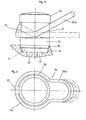
- the mixing valve is provided with a hand lever 3a, the annular arc 31 being passed through the casing sleeve 21 on the side facing away from the user.
- the hand lever 3a is guided around the lever head housing 2 with a bracket 34 and carries on the opposite side, ie on the side facing the user, a handle 32a.
Abstract
Description
- Die Erfindung betrifft eine Handhebelbetätigungsvorrichtung für Eingriffmischventile mit den im Oberbegriff des Anspruchs 1 angegebenen Merkmalen. Ein Eingriffmischventil dieser Gattung ist aus der Druckschrift DE-PS 30 18 771 bekannt, wobei die beiden Drehachsen sich im Ventilgehäuse schneiden und der Handhebel radial durch einen Schlitz im Mantel des Ventilgehäuses herausgeführt ist. Bedingt durch das erforderliche Auf-und Abschwenken des Handhebels erstreckt sich der das Innere des Ventils freigebende Schlitz über einen erheblichen Teil der Länge des Mantels. Außerdem ist es bekannt, bei Mischventilen mit in einen Sondergehäuse gekapselt angeordneten Ventilscheiben und einem an der Stirnseite eingeführten Handhebel den Handhebel mit einer fest verbundenen Haube zu versehen, die einen entsprechend gestalteten Kopfbereich des Ventilgehäuses umfaßt. Die Schwenk- und Taumelbewegungen des Handhebels werden hierbei allerdings zwangsläufig von der Haube mitvollzogen, was vielfach als unschön empfunden wird.
- Der Erfindung liegt die Aufgabe zugrunde, einen verbesserten Handhebel für die im Oberbegriff des Anspruchs 1 angegebenen Mischventile zu schaffen.
- Die Aufgabe wird erfindungsgemäß durch die im kennzeichnenden Teil des Anspruchs 1 angegebenen Merkmale gelöst. Mit diesen erfindungsgemäßen Maßnahmen wird mit einfachen Mitteln erreicht, daß das Hebelkopfgehäuse in jeder Hand- hebelstellung eine geschlossene Außenform aufweist, wobei eine ästhetisch ansprechende und pflegefreundliche Gestaltung der Armatur ermöglicht ist. Weitere Ausgestaltungen der Erfindung sind in den Ansprüchen 2 bis 7 angegeben. Der Handhebel kann zweckmäßig im Anschluß an eine den Ringbogen einschließende Verkröpfung mit einem etwa radial vom Hebelkopfgehäuse abstehenden Griffstück versehen werden. Den jeweiligen Gegebenheiten entsprechend kann aber auch der Handhebel im Anschluß an den äußeren Bereich des Ringbogens mit einem Bügel um das Hebelkopfgehäuse herumgeführt werden, so daß das etwa radial vorstehende Griffstück an der gegenüberliegenden Seite des Hebelkopfes angeordnet ist. Bei dieser Ausführung wäre dann der Ringbogen an der vom Benutzer abgekehrten Seite aus der Mantelhülse herausgeführt. Das den Handhebel aufnehmende Hebelkopfgehäuse kann vorteilhaft von einer drehbar aber axial festliegend, auf dem Ventilgehäuse gehalterten zylindrischen Mantelhülse gebildet werden, in der ein fensterartiger Längsschlitz zur Aufnahme des Ringbogens des Handhebels vorgesehen ist. Der obere Stirnbereich der Mantelhülse kann in einfacher Weise von einer Abdeckkappe mittels Schraub-, Schnapp-oder Bajonettverbindung verschlossen werden. Dabei ist es auch möglich, die Abdeckkappe mit Dekor- oder Strukturplatten zu versehen. Ferner kann der Handhebel durch die einfache Einfügungeines Steckrings in das Hebelkopfgehäuse mit einem Anschlag versehen werden, mit dem wahlweise eine Begrenzung des Schwenkbereichs um die erste Drehachse bestimmbar ist, und durch die Ausbildung eines Hebelarmes mit Stellschraube am Handhebel im inneren Bereich des Hebelkopfgehäuses ein Anschlag zur wahlweisen Begrenzung des Schwenkbereichs um die zweite Drehachse geschaffen werden. Schließlich kann der Handhebel auch als Bügel aus dem Hebelkopfgehäuse herausgeführt werden, wobei dann zwei parallel angeordnete Ringbögen aus z.B. Rundstabmaterial tangential durch entsprechend geformte Öffnungen in der Mantelhülse des Hebelkopfes hindurchgleiten und im äußeren Bereich, beispielsweise in einem bogenförmigen Griffstück, zusammengeführt sind.
- Ausführungsbeispiele der Erfindung sind in der Zeichnung dargestellt und werden im folgenden näher beschrieben. Es zeigt
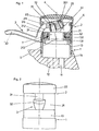
- Figur 1 ein in einer Sanitärarmatur eingesetztes Mischventil, teilweise geschnitten;
- Figur 2 das Mischventil gemäß Figur 1 in Seitenansicht;
- Figur 3 das Mischventil gemäß Figur 1 mit maximal verschwenktem Handhebel;
- Figur 4 das Mischventil gemäß Figur 3 in Draufsicht mit entfernter Abdeckkappe;
- Figur 5 ein anderes Ausführungsbeispiel eines Mischventils in Seitenansicht;
- Figur 6 das Mischventil gemäß Figur 5 in Draufsicht.
- Der Einfachheit halber sind bei den Ausführungsbeispielen in der Zeichnung gleiche oder entsprechende Elemente mit jeweils gleichen Bezugszeichen versehen.
- Das in den Figuren 1 bis 4 dargestellte Mischventil ist in einer Ventilkartusche 7 gekapselt angeordnet und wird von zwei aufeinanderliegenden Ventilscheiben, die z.B. aus Oxidkeramikmaterial hergestellt sind, gebildet. Die eine Scheibe ist festliegend in der Ventilkartusche angeordnet, während die andere mit einem in der Kartusche gelagerten und an der Stirnseite herausgefürten Kartuschenhebel 71 bewegbar angeordnet ist. Bei einer Drehbewegung um die erste Drehachse 4 wird die bewegliche oder Steuerscheibe zur Festscheibe verdreht und bewirkt somit eine Änderung des Mischungsverhältnisses, während ein Verschwenken des Kartuschenhebels 71 um die zweite Drehachse 5 die Steuerscheibe radial zur Festscheibe verschiebt und eine Änderung der Durchflußmenge bewirkt. Derartige Ventilkartuschen sind bekannt und handelsüblich, so daß in der Zeichnung diese Einzelheiten nicht dargestellt worden sind.
- Die Ventilkartusche 7 ist in einem Ventilgehäuse 1 mit Zulaufkanälen 11 für das kalte und warme Wasser und einem Ablaufkanal 12 für das Mischwasser angeordnet. Das Ventilgehäuse 1 wird dabei im wesentlichen von einer Schraubbuchse 13 und einem Gehäusesockel 14 gebildet, wobei die Ventilkartusche von der Schraubbuchse 13 aufgenommen und mittels Schraubgewinde 15 dicht und drehfest in den Gehäusesockel 14 mit den Zu- und Ablaufkanälen 11,12 gepreßt wird. Auf der Schraubbuchse 13 ist ein Hebelkopfgehäuse 2 mit einem radial herausgeführten Handhebel 3 angeordnet.
- Das Hebelkopfgehäuse 2 wird im wesentlichen von einer Mantelhülse 21 und einer Abdeckkappe 22 gebildet. Die Mantelhülse 21 ist mit einem Ringbund 213 auf einem Ansatz 131 der Schraubbuchse 13 drehbar aber axial mittels Sprengring 132 festliegend gelagert. An der äußeren Stirnseite der Mantelhülse 21 sind Schnappzungen 214 ausgebildet, mit denen die Abdeckkappe 22 auf der Mantelhülse 21 lösbar befestigt ist. Auf dem aus der Ventilkartusche 7 stirnseitig vorstehenden Kartuschenhebel 71 ist der Handhebel 3 formschlüssig aufgesteckt und mittels Befestigungsschraube zur zweiten Drehachse 72 gesichert. Der Handhebel 3 ist mit einem Ringbogen 31/ durch die Wandung der Mantelhülse 21 hindurchgeführt. Der Radius der inneren Ringbogenfläche 311 ist dabei so bemessen, daß er etwa dem Außendurchmesser der Mantelhülse 21 entspricht. Im Bereich des Ringbogens 31 weist die Mantelhülse 21 einen an der oberen Stirnfläche beginnenden Längsschlitz 211 auf, dessen Grund 212 etwa von dem Radius der inneren Ringbogenfläche 311 bestimmt ist. Der Längsschlitz 211 wird an der oberen Stirnfläche von dem Mantel der Abdeckkappe 22 begrenzt, wobei die Schnappzungen 214 so ausgebildet sind, daß der in der Mantelhülse 21 gebildete Schlitz vollständig von dem Ringbogen 31 ausgefüllt wird. An dem äußeren Ende des Ringbogens 31 ist mittels Verkröpfung ein sich radial von der Hülse erstreckendes Griffstück 32 angeformt.
- Wird nun der Handhebel 3 um die zweite Drehachse 5 verschwenkt, so kann der Ringbogen 31 durch den Schlitz in der Mantelhülse 21 hindurchgleiten, wobei aber der Schlitz der Mantelhülse 21 durch den Ringbogen 31 ausgefüllt bleibt. Wird der Handhebel 3 um die erste Drehachse 4 verschwenkt, so wird synchron mit der Schwenkbewegung des Handhebels 3 auch das Hebelkopfgehäuse 2 auf dem Ventilgehäuse 1 verdreht. Das Innere des Hebelkopfgehäuses 2 ist somit bei jeder Schwenkbewegung des Handhebels 3 gegen Spritzwasser etc. geschützt. Zur wahlweisen Begrenzung der Schwenkbewegung des Handhebels 3 um die erste Drehachse 4 ist auf dem Ansatz 131 des Ventilgehäuses 1 mittels Verzahnung 62 ein Steckring 6 aufsetzbar. Mit Hilfe von Anschlagnocken 61 kann die Schwenkbewegung des Handhebels 3 um die erste Drehachse 4 begrenzt werden, so daß z.B. der Warmwasserbereich des Mischventils wahlweise als Verbrühungsschutz reduziert werden kann. Außerdem ist der Handhebel 3 im Inneren des Hebelkopfgehäuses 2 mit einem Hebelarm 33 und einer Stellschraube 331 versehen. Mit Hilfe der Stellschraube 331 kann der Schwenkbereich um die zweite Drehachse 5 und damit die maximale Durchlaufmenge durch das Ventil reduziert werden. Als Anschlag für die Stellschraube 331 kann der auf dem Ventilgehäuse gehalterte Steckring 6 oder das Ventilgehäuse 1 dienen.
- Der Zusammenbau der Handhebelbetätigungsvorrichtung kann z.B. in folgender Weise vorgenommen werden:
- Zunächst wird die Ventilkartusche 7 in die Aufnahme des Gehäusesockels 14 eingefügt und durch Eindrehen in das Schraubgewinde 15 mit Hilfe eines an Schlüsselflächen 133 angreifenden Schlüssels dicht und drehfest in dem Ventilgehäuse 1 befestigt. Nunmehr wird die Mantelhülse 21 über den Ansatz 131 gestreift und mit dem Sprengring 132 in dieser Lage axial gesichert. Danach erfolgt das Aufschieben des Steckrings 6 auf die Verzahnung 62 des Ansatzes 131. Nunmehr kann der Handhebel 3 von oben in den stirnseitig offenen Längsschlitz 211 eingefügt und auf den aus der Ventilkartusche 7 stirnseitig vorstehenden Kartuschenhebel 71 aufgesteckt und mit der Befestigungsschraube 72 gesichert werden. Als Abschluß wird dann die Abdeckkappe 22 über die Schnappzungen 214 gedrückt und damit ist das Mischventil betriebsbereit.
- Soll nun die maximale Durchflußmenge durch das Mischventil begrenzt werden, so wird durch einfaches Abnehmen der Abdeckkappe 22 die Stellschraube 331 zugängig und eine entsprechende Justierung der maximalen Durchflußmenge kann vorgenommen werden. Bei einer Begrenzung oder Veränderung des einstellbaren Mischbereiches, z.B. um einen Verbrühungsschutz zu schaffen, ist neben der Abdeckkappe 22 noch der Handhebel 3 von dem Kartuschenhebel 71 abzunehmen. Nunmehr kann der Steckring 6 von dem Ansatz 131 abgezogen werden und in einer entsprechend verdrehten Stellung auf die Verzahnung wieder aufgesteckt und der Handhebel 3 mit der Abdeckkappe 22 entsprechend am Mischventil befestigt werden. Zur Erleichterung der Begrenzung des Mischbereiches können auf der Stirnseite des Ansatzes 131 und des Steckrings 6 Markierungen angeordnet werden.
- In den Figuren 5 und 6 ist ein anderes Ausführungsbeispiel eines Mischventils mit Handhebel gezeigt. Das Mischventil mit seinem Hebelkopfgehäuse entspricht dabei dem Ausführungsbeispiel in den Figuren 1 bis 4. Das Mischventil ist dabei mit einem Handhebel 3a versehen, wobei der Ringbogen 31 an der vom Benutzer abgekehrten Seite durch die Mantelhülse 21 hindurchgeführt ist. Am äußeren Ende des Ringbogens 31 ist der Handhebel 3a mit einem Bügel 34 um das Hebelkopfgehäuse 2 herumgeführt und trägt an der gegenüberliegenden Seite, d.h. an der dem Benutzer zugekehrten Seite,einen Handgriff 32a.
Claims (7)
Priority Applications (1)
| Application Number | Priority Date | Filing Date | Title |
|---|---|---|---|
| AT84112494T ATE31357T1 (de) | 1983-10-19 | 1984-10-17 | Handhebel fuer eingriffmischventile. |
Applications Claiming Priority (2)
| Application Number | Priority Date | Filing Date | Title |
|---|---|---|---|
| DE3337968 | 1983-10-19 | ||
| DE19833337968 DE3337968A1 (de) | 1983-10-19 | 1983-10-19 | Handhebel fuer eingriffmischventile |
Publications (3)
| Publication Number | Publication Date |
|---|---|
| EP0140275A2 true EP0140275A2 (de) | 1985-05-08 |
| EP0140275A3 EP0140275A3 (en) | 1985-10-23 |
| EP0140275B1 EP0140275B1 (de) | 1987-12-09 |
Family
ID=6212209
Family Applications (1)
| Application Number | Title | Priority Date | Filing Date |
|---|---|---|---|
| EP19840112494 Expired EP0140275B1 (de) | 1983-10-19 | 1984-10-17 | Handhebel für Eingriffmischventile |
Country Status (7)
| Country | Link |
|---|---|
| US (1) | US4610272A (de) |
| EP (1) | EP0140275B1 (de) |
| AT (1) | ATE31357T1 (de) |
| DE (2) | DE3337968A1 (de) |
| DK (1) | DK166041C (de) |
| FI (1) | FI77095C (de) |
| NO (1) | NO159412C (de) |
Cited By (4)
| Publication number | Priority date | Publication date | Assignee | Title |
|---|---|---|---|---|
| DE3510833A1 (de) * | 1985-03-26 | 1986-10-09 | Grohe Armaturen Friedrich | Mischventil |
| EP0718534A2 (de) * | 1991-06-17 | 1996-06-26 | Gustavsberg Vargarda Armatur Ab | Einhebelmischarmatur mit einer Vorrichtung zum Vermeiden von Wasserschlägen während des Hebelschliessvorganges |
| EP0818647A2 (de) | 1996-07-13 | 1998-01-14 | Friedrich Grohe Aktiengesellschaft | Mischventil mit einem Handhebel |
| EP2226434A1 (de) * | 2009-03-04 | 2010-09-08 | Kwc Ag | Sanitärarmatur mit Begrenzung des Wasserdurchflusses |
Families Citing this family (17)
| Publication number | Priority date | Publication date | Assignee | Title |
|---|---|---|---|---|
| SE449782B (sv) * | 1985-09-25 | 1987-05-18 | Vaergaarda Armaturfab Ab | Anordning vid blandningsventiler for temporer okning av flodet |
| DE3607349C2 (de) * | 1986-03-06 | 1995-07-20 | Grohe Armaturen Friedrich | Betätigungseinrichtung für Eingriffmischventile |
| US4739798A (en) * | 1986-11-10 | 1988-04-26 | Botnick Irlin H | Multiple control valve for mixing fluids |
| NZ226658A (en) * | 1987-10-27 | 1990-03-27 | Dorf Ind Pty Ltd | Single handle mixing valve including apertured discs |
| BE1003580A3 (fr) * | 1989-10-31 | 1992-04-28 | Staar Sa | Dispositif de reglage de debit pour robinet. |
| US5462224A (en) * | 1990-10-05 | 1995-10-31 | Toto Ltd. | Hot and cold water mixing discharge device |
| IT1260746B (it) * | 1992-04-30 | 1996-04-22 | Orlando Bosio | Dispositivo limitatore della portata in cartuccia miscelatrice monocomando per acqua calda e fredda |
| DE4223093A1 (de) * | 1992-07-14 | 1994-01-20 | Grohe Armaturen Friedrich | Eingriffmischventil |
| DE9300841U1 (de) * | 1993-01-22 | 1993-03-11 | Hans Grohe Gmbh & Co Kg, 7622 Schiltach, De | |
| US5522429A (en) * | 1993-11-30 | 1996-06-04 | Friedrich Grohe Aktiengesellschaft | Stroke limiter for single-lever mixing valve |
| US5363880A (en) * | 1994-01-24 | 1994-11-15 | Hsieh Yung Li | Hot/cold water mixing faucet with water temperature control |
| DE19510906A1 (de) * | 1995-03-24 | 1996-09-26 | Grohe Armaturen Friedrich | Mischventil mit einem Handhebel |
| IT1281653B1 (it) * | 1995-11-03 | 1998-02-20 | Galatron Srl | Dispositivo limitatore di portata per valvole miscelatrici di acqua calda e fredda |
| DE19628937A1 (de) * | 1996-07-18 | 1998-01-22 | Grohe Armaturen Friedrich | Betätigungseinrichtung für ein Einhebelmischventil |
| ITMI20030305A1 (it) * | 2003-02-20 | 2004-08-21 | Ugo Pizzi | Rubinetto miscelatore monocomando con miglorata regolazione del flusso. |
| DE102009008564B4 (de) * | 2009-02-12 | 2011-03-10 | Grohe Ag | Sanitärarmatur |
| DE102011115390B4 (de) | 2011-10-10 | 2019-02-14 | Grohe Ag | Durchflussrateneinstellvorrichtung für eine Sanitärarmatur |
Citations (8)
| Publication number | Priority date | Publication date | Assignee | Title |
|---|---|---|---|---|
| US3168112A (en) * | 1964-01-23 | 1965-02-02 | Hughlin E Klingler | Temperature mixing and diverting valve for domestic plumbing fixtures |
| DE7232994U (de) * | 1972-12-07 | H Eichelberg & Co Gmbh | Mischbatterie für sanitäre Anlagen | |
| DE1963451B2 (de) * | 1969-12-18 | 1977-12-08 | Heinrich Schuhe & Sohn, 5860 Iserlohn | Mischbatterie fuer sanitaere anlagen |
| DE2856300B2 (de) * | 1978-12-27 | 1980-10-16 | Friedrich Grohe Armaturenfabrik Gmbh & Co, 5870 Hemer | Handhebel für Eingriff-Mischbatterien |
| DE3018180A1 (de) * | 1980-05-13 | 1981-11-19 | Friedrich Grohe Armaturenfabrik Gmbh & Co, 5870 Hemer | Handhebel fuer eingriffmischbatterien |
| DE3018771C2 (de) * | 1980-05-16 | 1982-06-03 | Friedrich Grohe Armaturenfabrik Gmbh & Co, 5870 Hemer | Mischventil |
| DE3103891A1 (de) * | 1981-02-05 | 1982-09-02 | Hansa Metallwerke Ag, 7000 Stuttgart | Sanitaere einhebel-mischarmatur |
| US4375225A (en) * | 1980-12-10 | 1983-03-01 | F M Mattsson Ab | Mixing valve |
Family Cites Families (7)
| Publication number | Priority date | Publication date | Assignee | Title |
|---|---|---|---|---|
| US2635622A (en) * | 1947-08-11 | 1953-04-21 | Jesse C Owens | Antisiphonic ball cock |
| US2864398A (en) * | 1953-05-04 | 1958-12-16 | William P Green | Dual action handles |
| US3410487A (en) * | 1966-08-29 | 1968-11-12 | Pryde Inc | Faucet |
| US3964514A (en) * | 1974-07-01 | 1976-06-22 | Masco Corporation Of Indiana | Push-pull single handle water faucet valve |
| JPS5851139B2 (ja) * | 1978-05-18 | 1983-11-15 | 本田技研工業株式会社 | エンジンの絞り弁装置 |
| DE3068576D1 (en) * | 1979-05-04 | 1984-08-23 | Masco Corp | Single-control mixing cock with plates made of hard material |
| FI65659C (fi) * | 1980-10-30 | 1984-06-11 | Oras Oy | Engreppsblandningsventil |
-
1983
- 1983-10-19 DE DE19833337968 patent/DE3337968A1/de not_active Withdrawn
-
1984
- 1984-10-04 FI FI843907A patent/FI77095C/fi not_active IP Right Cessation
- 1984-10-17 DE DE8484112494T patent/DE3468068D1/de not_active Expired
- 1984-10-17 EP EP19840112494 patent/EP0140275B1/de not_active Expired
- 1984-10-17 AT AT84112494T patent/ATE31357T1/de not_active IP Right Cessation
- 1984-10-18 US US06/662,215 patent/US4610272A/en not_active Expired - Lifetime
- 1984-10-18 NO NO844175A patent/NO159412C/no unknown
- 1984-10-18 DK DK497584A patent/DK166041C/da not_active IP Right Cessation
Patent Citations (8)
| Publication number | Priority date | Publication date | Assignee | Title |
|---|---|---|---|---|
| DE7232994U (de) * | 1972-12-07 | H Eichelberg & Co Gmbh | Mischbatterie für sanitäre Anlagen | |
| US3168112A (en) * | 1964-01-23 | 1965-02-02 | Hughlin E Klingler | Temperature mixing and diverting valve for domestic plumbing fixtures |
| DE1963451B2 (de) * | 1969-12-18 | 1977-12-08 | Heinrich Schuhe & Sohn, 5860 Iserlohn | Mischbatterie fuer sanitaere anlagen |
| DE2856300B2 (de) * | 1978-12-27 | 1980-10-16 | Friedrich Grohe Armaturenfabrik Gmbh & Co, 5870 Hemer | Handhebel für Eingriff-Mischbatterien |
| DE3018180A1 (de) * | 1980-05-13 | 1981-11-19 | Friedrich Grohe Armaturenfabrik Gmbh & Co, 5870 Hemer | Handhebel fuer eingriffmischbatterien |
| DE3018771C2 (de) * | 1980-05-16 | 1982-06-03 | Friedrich Grohe Armaturenfabrik Gmbh & Co, 5870 Hemer | Mischventil |
| US4375225A (en) * | 1980-12-10 | 1983-03-01 | F M Mattsson Ab | Mixing valve |
| DE3103891A1 (de) * | 1981-02-05 | 1982-09-02 | Hansa Metallwerke Ag, 7000 Stuttgart | Sanitaere einhebel-mischarmatur |
Cited By (10)
| Publication number | Priority date | Publication date | Assignee | Title |
|---|---|---|---|---|
| DE3510833A1 (de) * | 1985-03-26 | 1986-10-09 | Grohe Armaturen Friedrich | Mischventil |
| EP0199960A2 (de) * | 1985-03-26 | 1986-11-05 | Friedrich Grohe Aktiengesellschaft | Mischventil |
| EP0199960A3 (en) * | 1985-03-26 | 1990-03-14 | Friedrich Grohe Armaturenfabrik Gmbh & Co | Mixing valve |
| EP0718534A2 (de) * | 1991-06-17 | 1996-06-26 | Gustavsberg Vargarda Armatur Ab | Einhebelmischarmatur mit einer Vorrichtung zum Vermeiden von Wasserschlägen während des Hebelschliessvorganges |
| EP0718534A3 (de) * | 1991-06-17 | 1997-05-02 | Gustavsberg Vargarda Armatur A | Einhebelmischarmatur mit einer Vorrichtung zum Vermeiden von Wasserschlägen während des Hebelschliessvorganges |
| EP0818647A2 (de) | 1996-07-13 | 1998-01-14 | Friedrich Grohe Aktiengesellschaft | Mischventil mit einem Handhebel |
| EP0818647A3 (de) * | 1996-07-13 | 1998-08-19 | Friedrich Grohe Aktiengesellschaft | Mischventil mit einem Handhebel |
| US5983939A (en) * | 1996-07-13 | 1999-11-16 | Friedrich Grohe Ag | Single-control mixing valve |
| EP2226434A1 (de) * | 2009-03-04 | 2010-09-08 | Kwc Ag | Sanitärarmatur mit Begrenzung des Wasserdurchflusses |
| US8418995B2 (en) | 2009-03-04 | 2013-04-16 | Kwc Ag | Sanitary fitting with limitation of water flow |
Also Published As
| Publication number | Publication date |
|---|---|
| DK497584A (da) | 1985-04-20 |
| FI843907A0 (fi) | 1984-10-04 |
| ATE31357T1 (de) | 1987-12-15 |
| US4610272A (en) | 1986-09-09 |
| FI77095B (fi) | 1988-09-30 |
| DK166041C (da) | 1993-08-02 |
| NO844175L (no) | 1985-04-22 |
| DK497584D0 (da) | 1984-10-18 |
| DE3468068D1 (de) | 1988-01-21 |
| EP0140275B1 (de) | 1987-12-09 |
| FI77095C (fi) | 1989-01-10 |
| DE3337968A1 (de) | 1985-05-02 |
| FI843907L (fi) | 1985-04-20 |
| EP0140275A3 (en) | 1985-10-23 |
| NO159412C (no) | 1988-12-21 |
| NO159412B (no) | 1988-09-12 |
| DK166041B (da) | 1993-03-01 |
Similar Documents
| Publication | Publication Date | Title |
|---|---|---|
| EP0140275B1 (de) | Handhebel für Eingriffmischventile | |
| DE2528717A1 (de) | Eingriffwasserhahn | |
| DE2216040A1 (de) | Mechanischer Mischhahn | |
| DE4035838A1 (de) | Wasserventil fuer sanitaere anlagen | |
| EP0778434B1 (de) | Stellgriff | |
| EP0745798B1 (de) | Stellgriff einer Sanitärarmatur | |
| EP0733839B1 (de) | Mischventil mit einem Handhebel | |
| DE2815990C2 (de) | Einhebel-Mischventil | |
| EP0530471B1 (de) | Stellvorrichtung für ein Mischventil | |
| EP1022634A1 (de) | Kartusche für Sanitärarmaturen | |
| DE2311840C2 (de) | Mischventil für zwei Fluidströmungen | |
| DE3013651C2 (de) | ||
| EP0621427A1 (de) | Mengenregulierventil | |
| DE4341620A1 (de) | Selbstschlußventil | |
| DE4338701A1 (de) | Misch- und Absperrventil | |
| EP0204882A1 (de) | Mischbatterie | |
| DE3911681A1 (de) | Mischhahn | |
| DE4437370A1 (de) | Betätigungseinrichtung für ein Einhebelmischventil | |
| EP2418409A1 (de) | Drehgriff | |
| DE4104656A1 (de) | Betaetigungsglied mit ueberlastsicherung | |
| DE2856300A1 (de) | Handhebel fuer eingriff-mischbatterien | |
| DE102004022029B4 (de) | Ventil für sanitäre Anlagen | |
| DE3306690C2 (de) | Wasserauslaufventil | |
| EP0204881A1 (de) | Mischbatterie | |
| DE3621713C2 (de) | Betätigungseinrichtung für ein sanitäres Einhebel-Mischventil |
Legal Events
| Date | Code | Title | Description |
|---|---|---|---|
| PUAI | Public reference made under article 153(3) epc to a published international application that has entered the european phase |
Free format text: ORIGINAL CODE: 0009012 |
|
| AK | Designated contracting states |
Designated state(s): AT BE CH DE FR GB IT LI NL SE |
|
| PUAL | Search report despatched |
Free format text: ORIGINAL CODE: 0009013 |
|
| AK | Designated contracting states |
Designated state(s): AT BE CH DE FR GB IT LI NL SE |
|
| 17P | Request for examination filed |
Effective date: 19851130 |
|
| 17Q | First examination report despatched |
Effective date: 19870128 |
|
| GRAA | (expected) grant |
Free format text: ORIGINAL CODE: 0009210 |
|
| AK | Designated contracting states |
Kind code of ref document: B1 Designated state(s): AT BE CH DE FR GB IT LI NL SE |
|
| REF | Corresponds to: |
Ref document number: 31357 Country of ref document: AT Date of ref document: 19871215 Kind code of ref document: T |
|
| REF | Corresponds to: |
Ref document number: 3468068 Country of ref document: DE Date of ref document: 19880121 |
|
| ITF | It: translation for a ep patent filed |
Owner name: STUDIO JAUMANN |
|
| ET | Fr: translation filed | ||
| GBT | Gb: translation of ep patent filed (gb section 77(6)(a)/1977) | ||
| PLBE | No opposition filed within time limit |
Free format text: ORIGINAL CODE: 0009261 |
|
| STAA | Information on the status of an ep patent application or granted ep patent |
Free format text: STATUS: NO OPPOSITION FILED WITHIN TIME LIMIT |
|
| 26N | No opposition filed | ||
| ITTA | It: last paid annual fee | ||
| REG | Reference to a national code |
Ref country code: CH Ref legal event code: PFA Free format text: FRIEDRICH GROHE AKTIENGESELLSCHAFT |
|
| REG | Reference to a national code |
Ref country code: FR Ref legal event code: CN |
|
| REG | Reference to a national code |
Ref country code: GB Ref legal event code: 732 |
|
| PGFP | Annual fee paid to national office [announced via postgrant information from national office to epo] |
Ref country code: BE Payment date: 19920921 Year of fee payment: 9 |
|
| PGFP | Annual fee paid to national office [announced via postgrant information from national office to epo] |
Ref country code: GB Payment date: 19921001 Year of fee payment: 9 |
|
| PGFP | Annual fee paid to national office [announced via postgrant information from national office to epo] |
Ref country code: CH Payment date: 19921016 Year of fee payment: 9 |
|
| PGFP | Annual fee paid to national office [announced via postgrant information from national office to epo] |
Ref country code: AT Payment date: 19921028 Year of fee payment: 9 |
|
| PGFP | Annual fee paid to national office [announced via postgrant information from national office to epo] |
Ref country code: NL Payment date: 19921031 Year of fee payment: 9 |
|
| ITPR | It: changes in ownership of a european patent |
Owner name: CAMBIO RAGIONE SOCIALE;FRIEDRICH GROHE AKTIENGESEL |
|
| PG25 | Lapsed in a contracting state [announced via postgrant information from national office to epo] |
Ref country code: GB Effective date: 19931017 Ref country code: AT Effective date: 19931017 |
|
| PG25 | Lapsed in a contracting state [announced via postgrant information from national office to epo] |
Ref country code: LI Effective date: 19931031 Ref country code: CH Effective date: 19931031 Ref country code: BE Effective date: 19931031 |
|
| BERE | Be: lapsed |
Owner name: FRIEDRICH GROHE A.G. Effective date: 19931031 |
|
| PG25 | Lapsed in a contracting state [announced via postgrant information from national office to epo] |
Ref country code: NL Effective date: 19940501 |
|
| GBPC | Gb: european patent ceased through non-payment of renewal fee |
Effective date: 19931017 |
|
| NLV4 | Nl: lapsed or anulled due to non-payment of the annual fee | ||
| REG | Reference to a national code |
Ref country code: CH Ref legal event code: PL |
|
| EAL | Se: european patent in force in sweden |
Ref document number: 84112494.4 |
|
| PGFP | Annual fee paid to national office [announced via postgrant information from national office to epo] |
Ref country code: SE Payment date: 19990920 Year of fee payment: 16 |
|
| PGFP | Annual fee paid to national office [announced via postgrant information from national office to epo] |
Ref country code: DE Payment date: 19991025 Year of fee payment: 16 |
|
| PGFP | Annual fee paid to national office [announced via postgrant information from national office to epo] |
Ref country code: FR Payment date: 19991029 Year of fee payment: 16 |
|
| PG25 | Lapsed in a contracting state [announced via postgrant information from national office to epo] |
Ref country code: SE Free format text: THE PATENT HAS BEEN ANNULLED BY A DECISION OF A NATIONAL AUTHORITY Effective date: 20001030 |
|
| REG | Reference to a national code |
Ref country code: FR Ref legal event code: CJ |
|
| EUG | Se: european patent has lapsed |
Ref document number: 84112494.4 |
|
| PG25 | Lapsed in a contracting state [announced via postgrant information from national office to epo] |
Ref country code: FR Free format text: LAPSE BECAUSE OF NON-PAYMENT OF DUE FEES Effective date: 20010629 |
|
| PG25 | Lapsed in a contracting state [announced via postgrant information from national office to epo] |
Ref country code: DE Free format text: LAPSE BECAUSE OF NON-PAYMENT OF DUE FEES Effective date: 20010703 |
|
| REG | Reference to a national code |
Ref country code: FR Ref legal event code: ST |