EP0139821B1 - Machine de traitement de fourrage - Google Patents
Machine de traitement de fourrage Download PDFInfo
- Publication number
- EP0139821B1 EP0139821B1 EP84104994A EP84104994A EP0139821B1 EP 0139821 B1 EP0139821 B1 EP 0139821B1 EP 84104994 A EP84104994 A EP 84104994A EP 84104994 A EP84104994 A EP 84104994A EP 0139821 B1 EP0139821 B1 EP 0139821B1
- Authority
- EP
- European Patent Office
- Prior art keywords
- machine according
- guide member
- conveyor
- conveying channel
- tools
- Prior art date
- Legal status (The legal status is an assumption and is not a legal conclusion. Google has not performed a legal analysis and makes no representation as to the accuracy of the status listed.)
- Expired
Links
Images


Classifications
-
- A—HUMAN NECESSITIES
- A01—AGRICULTURE; FORESTRY; ANIMAL HUSBANDRY; HUNTING; TRAPPING; FISHING
- A01D—HARVESTING; MOWING
- A01D43/00—Mowers combined with apparatus performing additional operations while mowing
- A01D43/10—Mowers combined with apparatus performing additional operations while mowing with means for crushing or bruising the mown crop
-
- Y—GENERAL TAGGING OF NEW TECHNOLOGICAL DEVELOPMENTS; GENERAL TAGGING OF CROSS-SECTIONAL TECHNOLOGIES SPANNING OVER SEVERAL SECTIONS OF THE IPC; TECHNICAL SUBJECTS COVERED BY FORMER USPC CROSS-REFERENCE ART COLLECTIONS [XRACs] AND DIGESTS
- Y10—TECHNICAL SUBJECTS COVERED BY FORMER USPC
- Y10S—TECHNICAL SUBJECTS COVERED BY FORMER USPC CROSS-REFERENCE ART COLLECTIONS [XRACs] AND DIGESTS
- Y10S56/00—Harvesters
- Y10S56/01—Crusher
Definitions
- the invention relates to a processing machine for agricultural crop material, consisting of a rotatingly drivable conveying member designed with conveying-effective processing tools and a guide member forming a conveying channel therewith.
- a processing machine for agricultural crop material consisting of a rotatingly drivable conveying member designed with conveying-effective processing tools and a guide member forming a conveying channel therewith.
- Such facilities have proven their worth in hay harvesting and silage processing. Thanks to an accelerated drying process, they significantly shorten the harvest time and enable farmers to work more efficiently.
- the conveyor channel which is made up of the conveyor drum and guide element, is provided with baffles which are rigidly attached to the guide element and are arranged in the conveyor channel and run transversely to the conveying flow of the stalk material.
- the stalk material flowing through the conveyor channel by means of a conveyor drum is shockingly injured at these chicanes.
- the guide member is designed to be adjustable and lockable in the region of the feed channel inlet opening.
- the intensity of the processing of the stalks occurs at the entrance of the conveyor channel due to its optionally adjustable opening cross-section and the position of the leading edge on the guide element.
- DE-B-21 31 134 describes an alternative embodiment of a chicane, which has proven to be advantageous in practice.
- the guide element above the conveyor drum is provided with a comb-like rake which extends over the entire width of the conveyor drum and, due to its adjustability, can optionally change the cross section of the conveyor channel, to the extent that the tines can protrude between the conveyor elements of the conveyor drum.
- DE-A-30 48 569 provides a conditioning device in which the stalk is processed by means of a rotor equipped with a brush arrangement.
- Conveyor tines protrude radially outward over the tips of the bristles of these brushes. The latter are designed to take the cut stalks from the ground or from a mower and transport them into the conveyor channel. The conveyor tines then emerge from the conveyor channel so that the brushes can work together with the guide wall to condition the crop.
- This type of preparation leaves a. relatively high crumbling losses and requires a high drive power.
- this object is achieved in that the guide member forming a conveying channel with a guide member forming a conveyor channel in a drum-like manner around the axis of rotation of the conveying member is designed such that the orbits of the processing tools intersect the guide member at the front and rear ends of the conveying channel.
- the cut forage can be processed more gently than before, in particular this procedure has a favorable effect on the delicate leaves of the stalks.
- the crumbling losses are reduced.
- the speed of the conveyor element can also be reduced to such an extent that the feed capacity is now maintained.
- the tangents to the orbits of the conveying tools form an acute angle a with the guide element, so that a constant feed flow is maintained.
- the preparation tools can be provided with a rough surface on the conveying side, which injures the crop.
- the measure has a particularly favorable effect if the preparation tools are provided with flanks that taper outwards. Two adjacent processing tools each form a wedge-shaped gap, which exerts an increased all-round friction effect when flowing through the narrowing conveying channel on the chuck.
- flanks have a rough surface, so that the straw material is exposed to increasing friction as it flows through the conveying channel, due to its increasingly narrowing cross section.
- the guide element is arranged such that it can be adjusted to selectively change the height of the feed channel. This option allows the preparation to be adapted to the nature of the feed.
- the guide member is removably attached.
- the latter can be provided with an outlet opening at its rear end.
- a driver protruding into the conveying channel can be provided between the preparation tools of the conveying member, which promotes feed intake and further transport.
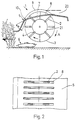
- a processing machine for agricultural stalks generally designated 1
- This processing machine has a conveying element 3 provided with conveying tools 2, which is driven in the direction of arrow A.
- conveying tools 2 which can also be rigidly attached to a shaft
- the processing machine has a guide element 5, the front end of which, in the case of an upstream disc mower 6, extends into the area of the still standing crop and preferably tilts it forward.
- the conveying member 3 forms a conveying channel 7 with the guiding member 5, the conveying member 3 cutting the guiding member 5 at its front and rear ends such that the preparation tools 2 protrude at least partially through the slot-like recesses 8 assigned to them on the guiding member 5.
- the delivery channel 7 initially narrows, as a result of which increased friction acts on the crop from all sides. Due to the subsequent divergence of the feed channel 7, the feed is dissolved again and placed loosely on the ground. To ensure a non-clogging, continuous flow, the tangents to the orbits of the processing tools 2 form an acute angle ⁇ with the guide member 5 at the front end of the conveying channel.
- a protective hood 9 is removably attached above the guide member 5, covering the slot-like recesses 8.
- a hinge 10 is provided for this. Straw material penetrating through the recesses 8 can be easily removed in this way.
- the protective hood could be provided with an opening 20 at its rear end, so that the feed emerging from the feed channel 7 through the recesses 8 can leave the space under the protective hood 9.
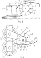
- FIG. 3 shows a mower preparation machine with an upstream drum mower 11.
- the conveying element 3 is slightly set back due to the drum body 12 placed on the mowing elements, without the feed flow being impaired thereby.
- a hinge 13 is attached to the front end of the guide member 5 so that the part adjoining the rear can be raised.
- FIG. 4 illustrates a mower preparation device in which the axis of rotation of the preparation machine 1 is arranged vertically or approximately parallel to the axes of rotation of the drum mower 11.
- the other organs are assigned to the processing machine 1 according to FIG. 1, the conveying channel 7 being designed in such a way that its front end opens into the conveying area between the mowing organs 13.
- a boom 14 connected to the mower 11 is provided for fastening the processing machine 1.
- FIG. 1 A mower conditioning device of an alternative embodiment is shown in FIG.
- the preparation machine 1 connected downstream of the drum mower 11 is provided with an undershot conveying channel 7.
- the flat guide element 5 extends with its front end to the mowing elements 13 and the conveying element 3, which rotates counter to the direction of travel, transports the cut stalk material through the undershot conveying channel 7, as shown in the previous figures Outside protection, the conveyor 3 is covered by a hood 15.
- the 6 shows a possible embodiment of the preparation tools 2 in cooperation with the guide member 5.
- the legs 16 of the Y-shaped preparation tools protrude through the recesses 8 of the guide member 5 to the outside.
- the dash-dotted line shows the lowest position of the guide member 5.
- the strips 17 formed by the recesses 8 have reinforcing ribs 18 in order to be able to absorb the increased pressure which is formed by the narrowing of the delivery channel 7.
- These reinforcing ribs 18 can be provided both on the inside and outside of the strips 17 and extend in the longitudinal direction thereof.
- FIG. 7 shows further embodiments of the preparation tools 2. According to the dash-dotted line, they are prismatic, but may be conically tapered towards the outside. In the second case, the recesses 8 should be provided in such a way that the processing tools 2 do not touch laterally at the greatest immersion depth.
- the conical ends of the preparation tools 2 produce higher frictional forces on the stalk material under the pressure of the guide member 5, this effect being able to be promoted by improving the coefficient of friction due to roughness.
- the roughing of the stalk is intensified by a rough surface on the inside of the guide organ.
- the surfaces of the processing tools 2 which have a positive effect on conveying are rough, for example with over-teeth.
- drivers 19 can be provided between the preparation tools 2, which alternatively catch the feed flowing backwards from the mower and guide them to the outer orbits of the preparation tools 2 due to the centrifugal force effect.
- the drivers 19 are, however, considerably shorter, so that they do not touch the guide element when the preparation tools 2 are deeply immersed in the recesses 8.
Landscapes
- Life Sciences & Earth Sciences (AREA)
- Environmental Sciences (AREA)
- Harvester Elements (AREA)
- Apparatuses For Bulk Treatment Of Fruits And Vegetables And Apparatuses For Preparing Feeds (AREA)
- Fodder In General (AREA)
- Electrical Discharge Machining, Electrochemical Machining, And Combined Machining (AREA)
- Harvesting Machines For Specific Crops (AREA)
Claims (15)
Priority Applications (1)
| Application Number | Priority Date | Filing Date | Title |
|---|---|---|---|
| AT84104994T ATE48063T1 (de) | 1983-08-15 | 1984-05-03 | Futteraufbereitungsmaschine. |
Applications Claiming Priority (2)
| Application Number | Priority Date | Filing Date | Title |
|---|---|---|---|
| CH4433/83A CH662470A5 (de) | 1983-08-15 | 1983-08-15 | Futteraufbereitungsmaschine fuer landwirtschaftliches halmgut. |
| CH4433/83 | 1983-08-15 |
Publications (3)
| Publication Number | Publication Date |
|---|---|
| EP0139821A2 EP0139821A2 (fr) | 1985-05-08 |
| EP0139821A3 EP0139821A3 (en) | 1985-10-30 |
| EP0139821B1 true EP0139821B1 (fr) | 1989-11-23 |
Family
ID=4276044
Family Applications (1)
| Application Number | Title | Priority Date | Filing Date |
|---|---|---|---|
| EP84104994A Expired EP0139821B1 (fr) | 1983-08-15 | 1984-05-03 | Machine de traitement de fourrage |
Country Status (6)
| Country | Link |
|---|---|
| US (1) | US4592194A (fr) |
| EP (1) | EP0139821B1 (fr) |
| AT (1) | ATE48063T1 (fr) |
| CH (1) | CH662470A5 (fr) |
| DE (1) | DE3480516D1 (fr) |
| DK (1) | DK391784A (fr) |
Cited By (1)
| Publication number | Priority date | Publication date | Assignee | Title |
|---|---|---|---|---|
| DE19951079A1 (de) * | 1999-10-23 | 2001-04-26 | Deere & Co | Erntegerät |
Families Citing this family (4)
| Publication number | Priority date | Publication date | Assignee | Title |
|---|---|---|---|---|
| US4991385A (en) * | 1984-09-27 | 1991-02-12 | National Research Development Corporation | Crop harvesting apparatus and methods |
| US4843806A (en) * | 1984-09-27 | 1989-07-04 | National Research Development Corporation | Crop harvesting apparatus and methods |
| US4722172A (en) * | 1985-02-04 | 1988-02-02 | Pearce Charles E | Harvesters |
| US7644566B2 (en) * | 2008-04-04 | 2010-01-12 | Cnh America Llc | Curtain to direct crop in a header |
Family Cites Families (10)
| Publication number | Priority date | Publication date | Assignee | Title |
|---|---|---|---|---|
| US2872772A (en) * | 1951-10-30 | 1959-02-10 | Sperry Rand Corp | Adjustable wind-guard for baler pick-up |
| CH502052A (de) * | 1969-01-31 | 1971-01-31 | Bucher Guyer Ag Masch | Heuerntemaschine |
| CH541271A (de) * | 1970-07-24 | 1973-09-15 | Bucher Guyer Ag Masch | Konditionierungsmaschine für landwirtschaftliches Halmgut |
| CH530751A (de) * | 1970-10-23 | 1972-11-30 | Bucher Guyer Ag Masch | Fahrbare Graskonditionierungsmaschine |
| US3747313A (en) * | 1972-03-31 | 1973-07-24 | F Denzin | Pick up devices for agricultural implements |
| US3785132A (en) * | 1972-06-01 | 1974-01-15 | D Wilson | Grain pick up |
| CH598743A5 (fr) * | 1976-08-10 | 1978-05-12 | Bucher Guyer Ag Masch | |
| EP0086458B1 (fr) * | 1978-03-31 | 1986-11-12 | National Research Development Corporation | Procédé et appareil de conditionnement de récoltes |
| DE3048569C2 (de) * | 1980-12-22 | 1986-03-27 | Bucher-Guyer AG Maschinenfabrik, Niederweningen, Zürich | Vorrichtung zum Aufbereiten geschnittenen Halmgutes |
| US4512146A (en) * | 1981-10-05 | 1985-04-23 | National Research De Development | Crop engaging device |
-
1983
- 1983-08-15 CH CH4433/83A patent/CH662470A5/de not_active IP Right Cessation
-
1984
- 1984-05-03 DE DE8484104994T patent/DE3480516D1/de not_active Expired
- 1984-05-03 EP EP84104994A patent/EP0139821B1/fr not_active Expired
- 1984-05-03 AT AT84104994T patent/ATE48063T1/de not_active IP Right Cessation
- 1984-07-12 US US06/630,083 patent/US4592194A/en not_active Expired - Fee Related
- 1984-08-15 DK DK391784A patent/DK391784A/da not_active Application Discontinuation
Cited By (1)
| Publication number | Priority date | Publication date | Assignee | Title |
|---|---|---|---|---|
| DE19951079A1 (de) * | 1999-10-23 | 2001-04-26 | Deere & Co | Erntegerät |
Also Published As
| Publication number | Publication date |
|---|---|
| EP0139821A2 (fr) | 1985-05-08 |
| US4592194A (en) | 1986-06-03 |
| EP0139821A3 (en) | 1985-10-30 |
| DK391784D0 (da) | 1984-08-15 |
| CH662470A5 (de) | 1987-10-15 |
| DE3480516D1 (en) | 1989-12-28 |
| DK391784A (da) | 1985-02-16 |
| ATE48063T1 (de) | 1989-12-15 |
Similar Documents
| Publication | Publication Date | Title |
|---|---|---|
| DE2131134C3 (de) | Kondiü'onierungsmaschine für landwirtschaftliches Halmgut | |
| DE2923597C2 (fr) | ||
| DE2004285A1 (de) | Heuerntemaschine | |
| EP0331784B1 (fr) | Hacheur de récolte | |
| DE2245602A1 (de) | Schraegfoerderer fuer maehdrescher | |
| DE2118914A1 (de) | Aus wenigstens einem Paar zusammenwirkender Mähkreisel bestehendes Mähwerk und nachgeschaltetem Quetschwalzenpaar bestehende Halmgutaufbereitungsmaschine | |
| DE3528372A1 (de) | Vorrichtung zum maehen und aufbereiten von halmgut | |
| DE3048569C2 (de) | Vorrichtung zum Aufbereiten geschnittenen Halmgutes | |
| EP0162431B1 (fr) | Machine de récolte | |
| DE1457944A1 (de) | Umlaufendes Sicherheits-Pflanzenschneidmesser | |
| EP2481277B1 (fr) | Mécanisme de battage d'une moissonneuse-batteuse | |
| DE19650058A1 (de) | Häckseltrommel | |
| EP0139821B1 (fr) | Machine de traitement de fourrage | |
| DE2652162A1 (de) | Maehdrescher der axialflussbauart | |
| DE3415508A1 (de) | Feldhaecksler | |
| DE2363293A1 (de) | Erntevorsatz fuer in reihe stehendes getreide, insbesondere fuer mais, mit einem rotor zum erfassen der ueber dem leitblech in die benachbarte reihe ueberhaengenden stengelteile | |
| DE1263386B (de) | Rundschlagmaeher | |
| EP3092885B1 (fr) | Faucheuse | |
| DE1226351B (de) | An das Maehwerk eines Maehdreschers oder einer anderen Erntemaschine fuer Getreide anbaubare Vorrichtung mit Einlegemaul zum Umstellen der Maschine auf die Ernte von Mais und aehnlichem Erntegut | |
| CH670031A5 (fr) | ||
| CH651721A5 (de) | Feldhaecksler fuer mais, mit einem geblaesefoerderer. | |
| DE1632831A1 (de) | Vorrichtung zum Ernten von Maiskolben fuer Maehmaschinen oder Maehdrescher | |
| DE950512C (de) | Dreschwerk | |
| DE2320126A1 (de) | Feldhaecksler | |
| DE2054585C (de) | Schneidvorrichtung fur Maiserntema schinen |
Legal Events
| Date | Code | Title | Description |
|---|---|---|---|
| PUAI | Public reference made under article 153(3) epc to a published international application that has entered the european phase |
Free format text: ORIGINAL CODE: 0009012 |
|
| 17P | Request for examination filed |
Effective date: 19840503 |
|
| AK | Designated contracting states |
Designated state(s): AT BE DE FR GB IT NL |
|
| PUAL | Search report despatched |
Free format text: ORIGINAL CODE: 0009013 |
|
| AK | Designated contracting states |
Designated state(s): AT BE DE FR GB IT NL |
|
| 17Q | First examination report despatched |
Effective date: 19861201 |
|
| GRAA | (expected) grant |
Free format text: ORIGINAL CODE: 0009210 |
|
| AK | Designated contracting states |
Kind code of ref document: B1 Designated state(s): AT BE DE FR GB IT NL |
|
| PG25 | Lapsed in a contracting state [announced via postgrant information from national office to epo] |
Ref country code: IT Free format text: LAPSE BECAUSE OF FAILURE TO SUBMIT A TRANSLATION OF THE DESCRIPTION OR TO PAY THE FEE WITHIN THE PRESCRIBED TIME-LIMIT;WARNING: LAPSES OF ITALIAN PATENTS WITH EFFECTIVE DATE BEFORE 2007 MAY HAVE OCCURRED AT ANY TIME BEFORE 2007. THE CORRECT EFFECTIVE DATE MAY BE DIFFERENT FROM THE ONE RECORDED. Effective date: 19891123 Ref country code: BE Effective date: 19891123 |
|
| REF | Corresponds to: |
Ref document number: 48063 Country of ref document: AT Date of ref document: 19891215 Kind code of ref document: T |
|
| REF | Corresponds to: |
Ref document number: 3480516 Country of ref document: DE Date of ref document: 19891228 |
|
| GBT | Gb: translation of ep patent filed (gb section 77(6)(a)/1977) | ||
| ET | Fr: translation filed | ||
| PLBE | No opposition filed within time limit |
Free format text: ORIGINAL CODE: 0009261 |
|
| STAA | Information on the status of an ep patent application or granted ep patent |
Free format text: STATUS: NO OPPOSITION FILED WITHIN TIME LIMIT |
|
| 26N | No opposition filed | ||
| PGFP | Annual fee paid to national office [announced via postgrant information from national office to epo] |
Ref country code: NL Payment date: 19910531 Year of fee payment: 8 |
|
| PGFP | Annual fee paid to national office [announced via postgrant information from national office to epo] |
Ref country code: DE Payment date: 19910613 Year of fee payment: 8 |
|
| PGFP | Annual fee paid to national office [announced via postgrant information from national office to epo] |
Ref country code: FR Payment date: 19910826 Year of fee payment: 8 |
|
| PGFP | Annual fee paid to national office [announced via postgrant information from national office to epo] |
Ref country code: AT Payment date: 19910827 Year of fee payment: 8 Ref country code: GB Payment date: 19910827 Year of fee payment: 8 |
|
| PG25 | Lapsed in a contracting state [announced via postgrant information from national office to epo] |
Ref country code: GB Effective date: 19920503 Ref country code: AT Effective date: 19920503 |
|
| PG25 | Lapsed in a contracting state [announced via postgrant information from national office to epo] |
Ref country code: NL Effective date: 19921201 |
|
| GBPC | Gb: european patent ceased through non-payment of renewal fee |
Effective date: 19920503 |
|
| NLV4 | Nl: lapsed or anulled due to non-payment of the annual fee | ||
| PG25 | Lapsed in a contracting state [announced via postgrant information from national office to epo] |
Ref country code: FR Effective date: 19930129 |
|
| PG25 | Lapsed in a contracting state [announced via postgrant information from national office to epo] |
Ref country code: DE Effective date: 19930202 |
|
| REG | Reference to a national code |
Ref country code: FR Ref legal event code: ST |