EP0138213B1 - Verfahren zur Schwelung von Rückständen der Kohlehydrierung - Google Patents
Verfahren zur Schwelung von Rückständen der Kohlehydrierung Download PDFInfo
- Publication number
- EP0138213B1 EP0138213B1 EP84112303A EP84112303A EP0138213B1 EP 0138213 B1 EP0138213 B1 EP 0138213B1 EP 84112303 A EP84112303 A EP 84112303A EP 84112303 A EP84112303 A EP 84112303A EP 0138213 B1 EP0138213 B1 EP 0138213B1
- Authority
- EP
- European Patent Office
- Prior art keywords
- hydrogenation
- residue
- bar
- screw extruder
- distillation
- Prior art date
- Legal status (The legal status is an assumption and is not a legal conclusion. Google has not performed a legal analysis and makes no representation as to the accuracy of the status listed.)
- Expired
Links
- 238000005984 hydrogenation reaction Methods 0.000 title claims description 38
- 239000003245 coal Substances 0.000 title claims description 17
- 238000000197 pyrolysis Methods 0.000 title description 5
- 238000000034 method Methods 0.000 claims description 24
- 238000004821 distillation Methods 0.000 claims description 10
- 239000007788 liquid Substances 0.000 claims description 7
- 230000006835 compression Effects 0.000 claims description 6
- 238000007906 compression Methods 0.000 claims description 6
- 238000001704 evaporation Methods 0.000 claims description 6
- 230000008020 evaporation Effects 0.000 claims description 6
- 239000007789 gas Substances 0.000 claims description 6
- 238000003763 carbonization Methods 0.000 claims 5
- 230000007423 decrease Effects 0.000 claims 1
- 238000006073 displacement reaction Methods 0.000 claims 1
- 239000003921 oil Substances 0.000 description 23
- 239000000047 product Substances 0.000 description 8
- 238000012545 processing Methods 0.000 description 6
- 239000007787 solid Substances 0.000 description 6
- 238000005516 engineering process Methods 0.000 description 5
- 238000000227 grinding Methods 0.000 description 5
- 238000010438 heat treatment Methods 0.000 description 5
- 239000003054 catalyst Substances 0.000 description 4
- 239000000470 constituent Substances 0.000 description 4
- 229910052739 hydrogen Inorganic materials 0.000 description 4
- 239000001257 hydrogen Substances 0.000 description 4
- UFHFLCQGNIYNRP-UHFFFAOYSA-N Hydrogen Chemical compound [H][H] UFHFLCQGNIYNRP-UHFFFAOYSA-N 0.000 description 3
- XEEYBQQBJWHFJM-UHFFFAOYSA-N Iron Chemical compound [Fe] XEEYBQQBJWHFJM-UHFFFAOYSA-N 0.000 description 3
- 238000006243 chemical reaction Methods 0.000 description 3
- 239000007795 chemical reaction product Substances 0.000 description 3
- 239000012263 liquid product Substances 0.000 description 3
- 239000000463 material Substances 0.000 description 3
- 239000004033 plastic Substances 0.000 description 3
- 229920003023 plastic Polymers 0.000 description 3
- 238000006116 polymerization reaction Methods 0.000 description 3
- 238000000926 separation method Methods 0.000 description 3
- 229910052799 carbon Inorganic materials 0.000 description 2
- 239000000571 coke Substances 0.000 description 2
- 238000004519 manufacturing process Methods 0.000 description 2
- 239000000178 monomer Substances 0.000 description 2
- 238000005292 vacuum distillation Methods 0.000 description 2
- OKTJSMMVPCPJKN-UHFFFAOYSA-N Carbon Chemical compound [C] OKTJSMMVPCPJKN-UHFFFAOYSA-N 0.000 description 1
- UGFAIRIUMAVXCW-UHFFFAOYSA-N Carbon monoxide Chemical compound [O+]#[C-] UGFAIRIUMAVXCW-UHFFFAOYSA-N 0.000 description 1
- 238000003723 Smelting Methods 0.000 description 1
- NINIDFKCEFEMDL-UHFFFAOYSA-N Sulfur Chemical compound [S] NINIDFKCEFEMDL-UHFFFAOYSA-N 0.000 description 1
- 239000002956 ash Substances 0.000 description 1
- 238000009835 boiling Methods 0.000 description 1
- 125000000837 carbohydrate group Chemical group 0.000 description 1
- 238000009903 catalytic hydrogenation reaction Methods 0.000 description 1
- 238000001816 cooling Methods 0.000 description 1
- 238000013461 design Methods 0.000 description 1
- 238000011161 development Methods 0.000 description 1
- 208000001848 dysentery Diseases 0.000 description 1
- 238000000605 extraction Methods 0.000 description 1
- 239000003546 flue gas Substances 0.000 description 1
- 239000000446 fuel Substances 0.000 description 1
- 239000003517 fume Substances 0.000 description 1
- 238000002309 gasification Methods 0.000 description 1
- 229930195733 hydrocarbon Natural products 0.000 description 1
- 150000002430 hydrocarbons Chemical class 0.000 description 1
- 150000002431 hydrogen Chemical class 0.000 description 1
- 230000006698 induction Effects 0.000 description 1
- 239000000543 intermediate Substances 0.000 description 1
- 239000013067 intermediate product Substances 0.000 description 1
- 229910052742 iron Inorganic materials 0.000 description 1
- 239000003077 lignite Substances 0.000 description 1
- 238000010327 methods by industry Methods 0.000 description 1
- 239000002480 mineral oil Substances 0.000 description 1
- 239000000203 mixture Substances 0.000 description 1
- 239000004058 oil shale Substances 0.000 description 1
- 235000011837 pasties Nutrition 0.000 description 1
- 238000005191 phase separation Methods 0.000 description 1
- 239000010802 sludge Substances 0.000 description 1
- 229910052717 sulfur Inorganic materials 0.000 description 1
- 239000011593 sulfur Substances 0.000 description 1
- 239000011269 tar Substances 0.000 description 1
- 238000012360 testing method Methods 0.000 description 1
- 238000012546 transfer Methods 0.000 description 1
- 238000007738 vacuum evaporation Methods 0.000 description 1
Images
Classifications
-
- C—CHEMISTRY; METALLURGY
- C10—PETROLEUM, GAS OR COKE INDUSTRIES; TECHNICAL GASES CONTAINING CARBON MONOXIDE; FUELS; LUBRICANTS; PEAT
- C10G—CRACKING HYDROCARBON OILS; PRODUCTION OF LIQUID HYDROCARBON MIXTURES, e.g. BY DESTRUCTIVE HYDROGENATION, OLIGOMERISATION, POLYMERISATION; RECOVERY OF HYDROCARBON OILS FROM OIL-SHALE, OIL-SAND, OR GASES; REFINING MIXTURES MAINLY CONSISTING OF HYDROCARBONS; REFORMING OF NAPHTHA; MINERAL WAXES
- C10G1/00—Production of liquid hydrocarbon mixtures from oil-shale, oil-sand, or non-melting solid carbonaceous or similar materials, e.g. wood, coal
- C10G1/02—Production of liquid hydrocarbon mixtures from oil-shale, oil-sand, or non-melting solid carbonaceous or similar materials, e.g. wood, coal by distillation
-
- C—CHEMISTRY; METALLURGY
- C10—PETROLEUM, GAS OR COKE INDUSTRIES; TECHNICAL GASES CONTAINING CARBON MONOXIDE; FUELS; LUBRICANTS; PEAT
- C10B—DESTRUCTIVE DISTILLATION OF CARBONACEOUS MATERIALS FOR PRODUCTION OF GAS, COKE, TAR, OR SIMILAR MATERIALS
- C10B7/00—Coke ovens with mechanical conveying means for the raw material inside the oven
- C10B7/10—Coke ovens with mechanical conveying means for the raw material inside the oven with conveyor-screws
Definitions
- coal is hydrogenated by reaction with hydrogen at temperatures of 250-550 ° C., preferably 350 to 490 ° C. and pressures of 50-700 bar, preferably 100-350 bar, in particular in the presence of catalysts becomes.
- the products produced are solid or viscous hydrogenation residues at room temperature.
- Both hard coal and lignite can be used in the hydrogenation (see W. Krönig, "The catalytic hydrogenation of coal, tars and mineral oils", Springer Verlag, Berlin, Göttingen, Heidelberg 1950).
- the corresponding technologies were developed and used for technical maturity in the years 1920-1945.
- the hydrogenation technologies according to BERGIUS-PIER and POTT-BROCHE are to be mentioned as basic processes.
- the oils obtained can be used as grinding oils or grinding oil components for the coal. Smoldering was carried out in ball ovens or screw ovens. During smoldering, even the per se vaporizable oils are broken down pyrolytically, so that there is a loss of valuable hydrogenation products.
- the evaporable oils can be removed by vacuum distillation of the hydrogenation residue.
- the oils obtained are high-quality rubbing oils or can be further hydrated under relatively mild conditions.
- handling the vacuum residue poses considerable problems. In particular, the discharge from the vacuum column and the transport for further processing are extremely difficult owing to the high toughness of the highly solids-enriched material.
- DE-C-704 444 describes a process for working up residues of the coal hydrogenation by topping the centrifugal residues at 350 to 450 ° C., preferably in the presence of gases and subsequent smoldering in a smoldering furnace above 450 ° C.
- GB-A-288148 describes the extraction of oil-like constituents from oil-containing residues of the coal hydrogenation using the process heat.
- the oily residue is stripped with hot gases or vapors, which can be passed through by means of a screw conveyor arranged in a closed tube.
- the deoiled residue can then be subjected to dry distillation and gasification in a separate process step.
- Document FR-A-550 217 describes a process for the dry distillation of oil shale, the dry distillation taking place in a screw conveyor at temperatures of 350 to 450 ° C and at pressures of 0.1 atmosphere (i.e. 0.1 bar).
- Single or multi-shaft screw machines with gas or steam discharge are known, for. B. from US-A-1 156 096 and US-A-2 615 199. They are used specifically in the manufacture of plastics, and serve u. a. for gas or monomer removal from polymerization mixtures (see M. Herrmann, “Screw machines in process engineering”, Springer Verlag, Berlin, Heidelberg, New York 1972). Although the difficulties associated with oil separation have been known since the start of industrial-scale coal hydrogenation, vacuum screw machines have so far not been used for processing carbohydrate residues.
- the processing of hydrogenation residues has different objectives than in the production of plastics:
- the screw machine is part of the polymerization reactor, whereby the polymerization reaction is terminated by removing the monomers in the vacuum zone, whereas in the case of coal hydrogenation, the enrichment of solids in the hydrogenation residue is expedient is.
- the object of the present invention is to overcome these difficulties and to improve the overall liquid product yield of the process.
- this is done by subjecting the residue of the carbon hydrogenation to distillation under reduced pressure in a single- or multi-shaft screw machine, removing the evaporable fractions and then smelting the remaining material in the screw machine.
- the hydrogenation residue which constantly increases its viscosity during distillation and smoldering, is continuously circulated by screws and thereby through the distillation zone and Smoldering zone of the screw machine guided, whereby first the evaporable components, then the volatile components obtainable by pyrolysis are withdrawn.
- the screw machine has an evaporation zone separated from one another by a mechanical compression stage and a smoldering zone.
- pressures of 0.01 to 0.6 bar preferably 0.02 to 0.1 bar
- the pressure drops from 0.6, preferably 0.1 bar to 0.01, preferably 0.02, over the length of the screw machine from the entry of the hydrogenation sludge to its exit. This measure reduces the risk of disturbances in the distillation process in the screw machine.
- the distillation of the hydrogenation residue in the screw machine is carried out in particular at temperatures of 200-400 ° C, preferably 250-350 ° C.
- the temperature rises over the length of the screw machine from the entry to the exit of the hydrogenation residue from 200, preferably 250 ° C. to 400, preferably 350 ° C., under constant pressure or falling over the length of the screw machine. This shortens the time during which the hydrogenation residue assumes high temperatures which favor changes and facilitates the further processing of the residue freed from the volatile constituents.
- the non-evaporated material is heated to higher temperatures, preferably 350-600 ° C., and smelted at these temperatures, in particular at atmospheric pressure or even at a pressure below it.
- the screw machine expediently has a smoldering zone in addition to the distillation zone, into which the hydrogenation residue is conveyed through the screws after passing through the former.
- the resulting sulfur fumes are extracted separately from the oil vapors.
- the resulting coke can finally z. B. can be used as fuel. Residues up to a final viscosity of approximately 2000 mPas (250 ° C.) can be handled in the distillate removal by the process according to the invention.
- oils withdrawn in gaseous form from the screw machine are expediently used as grating oils or with the other hydrogenating oils, e.g. the gaseous hydrogenation products leaving the hot separator combined and together with these the further treatment, for. B. subjected to a hydrogenation.
- the present method is suitable for processing all hydrogenation residues which occur in high-pressure coal hydrogenation processes in which coal is mashed with grinding oil and reacted together with hydrogen hydrogen and, if appropriate, in the presence of a catalyst at elevated pressure and elevated temperature, for example by the so-called Bergius-Pier process .
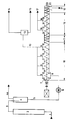
- a typical gas flame coal of the Ruhr area is mashed with a grinding oil returned from the process and fed together with the hydrogenation hydrogen and with the addition of an iron catalyst at 300 bar and 470 ° C after preheating via line 1 under process pressure hydrogenation reactor 2.
- the reaction product leaves the reactor 2 via line 3 and is fed to the hot separator 4, in which the products volatile under the prevailing conditions are separated from the solid or liquid reaction products under process pressure and at 460 ° C.
- a vacuum of 0.1 bar is generated in the screw machine 7, which is equipped with a twin screw, via a vacuum line 14.
- the hydrogenation residue used, which is fed to the screw machine 7 via nozzle 8, contained 0.5 t of oil with an initial boiling point of 325 ° C. or above, 0.15 t of higher molecular weight components, which were about 0.1 t as asphaltenes and about 0 , 05 t were determined as pre-asphaltenes and 0.35 t of inorganic components, which were composed of 0.24 t of ash and 0.11 t of unreacted coal.
- the ash content was about 32 wt .-% of Si0 2 to 26 wt .-% of AI z 0 3, consisting determined to 25 wt .-% of Fe 2 0 3 and 17 wt .-% other components.
- distillate was separated off at the pressure of 0.1 bar, the hydrogenation residue in the vacuum twin-screw machine 7 being heated from 350 to 450 ° C. during the distillate separation. 0.40 t of distillable components of the oil portion evaporated, which were drawn off via the connecting pieces 9 from the evaporation zone 18 and, after cooling (not shown), via line 10 and via condensate container 13 by means of line 15.
- the softening point of the residue after passing through the evaporation zone 18 was 180 ° C.
- the viscosity of the same residue at 250 ° C was determined to be 1500 mPas.
- the distilled constituents withdrawn via line 15 can be used as valuable rubbing oil components are returned to the hydrogenation.
- Evaporation zone 18 and smoldering zone 19 are separated by a mechanical compression stage 11, which is realized in a known manner by suitable design of the screw and the arrangement of suitable screw elements in this area. This results in a compression of the residue, which contains only 0.1 t of residual oil in addition to inorganic constituents and higher molecular weight intermediate products, before it enters the smoldering zone 19 and is heated to 600 ° C. here.
- a further 0.2 t of distillate are obtained in the smoldering zone 19, which is withdrawn from the smoldering zone via the connection 16 and line 17 and can likewise be recycled into the hydrogenation as a valuable grinding oil component.
- the residue after the smoldering consisted of 87% by weight of inorganic components and 13% by weight of other residue components, in particular coke-like products, and was drawn off after passing through a compression zone 12 via connection piece 20 and line 21.
- the screw machine was heated by means of jacket heating of the screw machine using superheated steam in the evaporation zone and flue gas in the smoldering zone.
- the heating can also be carried out by means of electrically heated heating jaws or by induction heating or, in the case of jacket heating, by heat transfer oils.
Landscapes
- Chemical & Material Sciences (AREA)
- Engineering & Computer Science (AREA)
- Oil, Petroleum & Natural Gas (AREA)
- Organic Chemistry (AREA)
- Materials Engineering (AREA)
- Life Sciences & Earth Sciences (AREA)
- Wood Science & Technology (AREA)
- Chemical Kinetics & Catalysis (AREA)
- General Chemical & Material Sciences (AREA)
- Production Of Liquid Hydrocarbon Mixture For Refining Petroleum (AREA)
Description
- Zur Hydrierung von Kohle sind Verfahren bekannt, bei denen Kohle durch Reaktion mit Wasserstoff bei Temperaturen von 250-550 °C, vorzugsweise 350 bis 490 °C und Drücken von 50-700 bar, vorzugsweise 100-350 bar, insbesondere in Gegenwart von Katalysatoren hydriert wird. Als Produkte entstehen neben flüssigen und gasförmigen Kohlenwasserstoffen bei Raumtemperatur feste bzw. zähflüssige Hydrierrückstände. Sowohl Steinkohlen als auch Braunkohlen können dabei in die Hydrierung eingesetzt werden (s. W. Krönig, «Die katalytische Hydrierung von Kohlen, Teeren und Mineralölen», Springer Verlag, Berlin, Göttingen, Heidelberg 1950). Die entsprechenden Technologien wurden in den Jahren 1920-1945 zur technischen Reife entwickelt und eingesetzt. Als Basisverfahren sind die Hydriertechnologien nach BERGIUS-PIER und POTT-BROCHE anzuführen.
- Aufbauend auf diesen Verfahren wurden in neuerer zeit spezielle Technologien entwickelt und im Klein- bzw. Pilotanlagenmassstab erprobt. Dazu sind insbesondere die EDS-Technologie, SRC, das H-COAL-Verfahren sowie die Neue Deutsche Technologie zu nennen. Letzteres wird seit 1981 in der Grossversuchsanlage Bottrop erprobt (s. H.G. Frank u. A. Knop, «Kohleveredlung», Springer Verlag, Berlin, Heidelberg, New York 1979, S. 228-251).
- Allen diesen Verfahren ist gemeinsam, dass die Abtrennung der Hydrierrückstände von den gasförmigen bzw. flüssigen Produkten in Heissabscheidern erfolgt, wobei die Phasenseparierung unter Reaktionsdruck bei Reaktionstemperatur bzw. wenig darunter liegenden Temperaturen erfolgt. Von besonderem Interesse ist dabei die Aufarbeitung der Hydrierrückstände, da diese neben Feststoffen wie nicht umgesetzter Kohle, Asche, Katalysatoren und nicht verdampfbaren flüssigen oder pastösen Zwischenprodukten wie Asphaltenen und Präasphaltenen wertvolle verdampfbare Produktöle enthalten, die zur Steigerung der Flüssigproduktausbeute abzutrennen sind.
- Zur Abtrennung dieser verdampfbaren Ölbeimengungen wurden unter anderem Schwelung oder Vakuumdestillation angewandt. Die gewonnenen Öle können als Anreibeöle bzw. Anreibölkomponenten für die Einsatzkohle verwendet werden. Die Schwelung wurde in Kugelöfen oder Schneckenöfen vorgenommen. Während der Schwelung erfolgt ein pyrolytischer Abbau selbst der an sich verdampfbaren Öle, so dass ein Verlust an wertvollen Hydrierprodukten eintritt. Durch Vakuumdestillation des Hydrierrückstandes können die verdampfbaren Öle abgetrennt werden. Die dabei gewonnenen Öle stellen hochwertige Anreibeöle dar bzw. können unter verhältnismässig milden Bedingungen weiter aufhydriert werden. Allerdings wirft die Handhabung des Vakuumrückstandes erhebliche Probleme auf. Insbesondere gestaltet sich das Austragen aus der Vakuumkolonne sowie der Transport zur Weiterverarbeitung aufgrund der hohen Zähigkeit des stark feststoffangereicherten Materials äusserst schwierig.
- In der Druckschrift DE-C-704 444 ist ein Verfahren beschrieben zur Aufarbeitung von Rückständen der Kohlehydrierung durch Abtoppen der Schleuderrückstände bei 350 bis 450°C, vorzugsweise in Gegenwart von Gasen und anschliessendes Schwelen in einem Schwelofen oberhalb 450°C.
- In der Druckschrift GB-A-288148 ist die Gewinnung ölartiger Bestandteile aus ölhaltigen Rückständen der Kohlehydrierung unter Ausnutzung der Prozesswärme beschrieben. Der ölhaltige Rückstand wird mit heissen Gasen oder Dämpfen gestrippt, wobei dieser mittels eines in einem geschlossenen RohrangeordnetenSchneckenförderelementes durchgesetzt werden kann. Der entölte Rückstand kann in einer getrennten Verfahrensstufe anschliessend einer Trockendestillation und einer Vergasung unterworfen werden.
- In der Druckschrift FR-A-550 217 wird ein Verfahren zur trockenen Destillation von Olschiefer beschrieben, wobei die Trockendestillation in einer Schneckenfördereinrichtung bei Temperaturen von 350 bis 450°C und bei Drücken von 0,1 Atmosphären (d.h. 0,1 bar) ergolgt.
- Ein- oder mehrwellige Schneckenmaschinen mit Gas- oder Dampfabführung sind bekannt, z. B. aus den US-A-1 156 096 und US-A-2 615 199. Sie werden spezielt in der Kunststoffherstellung eingesetzt, und dienen dort u. a. zur Gas- bzw. Monomerenentfernung aus Polymerisationsgemischen (s. M. Herrmann, «Schneckenmaschinen in der Verfahrenstechnik», Springer Verlag, Berlin, Heidelberg, New York 1972). Obwohl seit Beginn der im technischen Massstab durchgeführten Kohlehydrierung die mit der Ölabtrennung verbundenen Schwierigkeiten bekannt waren, wurden Vakuumschneckenmaschinen bislang nicht für die Aufarbeitung von Kohlehydrierrückständen eingesetzt. Bei der Aufarbeitung von Hydrierrückständen liegen andere Zielsetzungen als bei der Kunststoffherstellung vor: In der Kunststoffindustrie stellt di Schneckenmaschine einen Teil des Polymerisationsreaktors dar, wobei über die Monomerenentfernung in der Vakuumzone ein Abbruch der Polymerisationsreaktion herbeigeführt wird, wohingegen im Fall der Kohlehydrierung die Feststoffanreicherung im Hydrierrückstand zielführend ist.
- Die vorliegende Erfindung hat sich die Aufgabe gestellt, diese Schwierigkeiten zu überwinden und die Gesamtflüssigproduktausbeute des Verfahrens zu verbessern.
- Erfindungsgemäss geschieht dies dadurch, dass der Rückstand der Kohlehydrierung in einer ein- oder mehrwelligen Schneckenmaschine einer Destillation unter vermindertem Druck unterworfen wird, hierbei die verdampfbaren Anteile abgezogen werden und das verbleibende Gut anschliessend in der Schneckenmaschine geschwelt wird. Der während der Destillation und Schwelung ständig seine Viskosität erhöhende Hydrierrückstand wird durch Schnecken laufend umgewälzt und dabei durch die Destillationszone und die Schwelzone der Schneckenmaschine geführt, wobei ihm zunächst die verdampfbaren Bestandteile, dann die durch Pyrolyse gewinnbaren flüchtigen Bestandteile entzogen werden. Die Schneckenmaschine weist eine durch eine maschinentechnische Kompressionsstufe voneinander getrennte Verdampfungszone und eine Schwelzone auf.
- Bei der Destillation des Hydrierrückstandes in der ein- oder mehrwelligen Schneckenmaschine werden insbesondere Drücke von 0,01 bis 0,6 bar, vorzugsweise 0,02 bis 0,1 bar angewandt. Nach einer Weiterbildung der Erfindung fällt über die Länge der Schneckenmaschine vom Eintritt des Hydrierabschlammes zu dessen Austritt der Druck von 0,6, vorzugsweise 0,1 bar auf 0,01, vorzugsweise 0,02 ab. Diese Massnahme verringert die Gefahr von Störungen des Destillationsvorganges in der Schneckenmaschine.
- Die Destillation des Hydrierrückstandes in der Schneckenmaschine erfolgt insbesondere bei Temperaturen von 200-400°C, vorzugsweise 250-350°C. Nach einer weiteren Ausbildung der Erfindung steigt über die Länge der Schneckenmaschine vom Eintritt zum Austritt des Hydrierrückstandes die Temperatur von 200, vorzugsweise 250 °C auf 400, vorzugsweise 350 °C unter konstantem bzw. über die Länge der Schneckenmaschine fallendem Druck an. Hierdurch wird die Zeit, während der Hydrierrückstand hohe, Veränderungen begünstigende Temperaturen annimmt, verkürzt und die weitere Verarbeitung des von den flüchtigen Bestandteilen befreiten Rückstandes erleichtert.
- Das nicht verdampfte Gut wird nach der Destillation auf höhere Temperaturen, vorzugsweise 350-600 °C erhitzt und bei diesen Temperaturen, insbesondere bei Atmosphärendruck oder auch bei einem darunter liegenden Druck geschwelt. Zweckmässigerweise besitzt die Schneckenmaschine hierfür neben der Destillierzone eine Schwelzone, in die der Hydrierrückstand nach Durchlaufen der ersteren durch die Schnecken gefördert wird. Die entstehenden Schweldämpfe werden getrennt von den Öldämpfen abgezogen. Der anfallende Koks schliesslich kann z. B. als Brennmaterial eingesetzt werden. Nach dem erfindungsgemässen Verfahren können Rückstände bis zu einer Endviskosität von etwa 2000 mPas (250°C) bei der Destillatabtrennung gehandhabt werden.
- Die gasförmig aus der Schneckenmaschine abgezogenen Öle werden zweckmässigerweise als Anreibeöle eingesetzt oder mit den übrigen Hydrierölen, z.B. den die Heissabscheider gasförmig verlassenden Hydrierprodukten vereinigt und zusammen mit diesen der Weiterbehandlung, z. B. einer Hydrierung unterworfen.
- Das vorliegende Verfahren ist geeignet zur Verarbeitung sämtlicher Hydrierrückstände, die bei Hochdruckkohlehydrierprozessen anfallen, bei denen Kohle mit Anreibeöl angemaischt wird und gemeinsam mit Hydrierwasserstoff und gegebenenfalls in Gegenwart eines Katalysators bei erhöhtem Druck und erhöhter Temperatur umgesetzt wird, beispielsweise nach dem sogenannten Bergius-Pier-Verfahren.
- Die Erfindung wird anhand des nachfolgenden Ausführungsbeispiels und der Zeichnung weiter erläutert.
- Eine typische Gasflammkohle des Ruhrgebiets wird nach Zerkleinerung mit einem aus dem Verfahren zurückgeführten Anreibeöl angemaischt und gemeinsam mit dem Hydrierwasserstoff und unter Zugabe eines Eisenkatalysators bei 300 bar und 470 °C nach Vorheizung über Leitung 1 unter Prozessdruck Hydrierreaktor 2 zugeführt.
- Das Umsetzungsprodukt verlässt den Reaktor 2 über Leitung 3 und wird Heissabscheider 4 zugeführt, in welchem unter Prozessdruck und bei 460°C die Abtrennung der unter den herrschenden Bedingungen flüchtigen Produkte von den festen bzw. flüssigen Umsetzungsprodukten erfolgt.
- Diese flüchtigen Produkte werden über Leitung 4a über Kopf abgezogen und in bekannter Weise weiter aufgearbeitet. Die festen und flüssigen Reaktionsprodukte werden nach Entspannung auf Atmosphärendruck über Leitung 5 in den Vakuumschneckenverdampfer 7 mit integrierter Verdichtungs- und Schwelungszone eingespeist.
- Hierbei erfolgt der Eintritt in den Vakuumschneckenverdampfer 7 von unten her über Stutzen 8 in den Flüssigraum, um damit einen Abschluss des Zulaufstromes der Produkte aus dem Heissabscheider zu der Vakuumverdampfungszone 18 zu bekommen. Als Förderorgan für den Zulaufstrom wird ein zwangsförderndes Pumpensystem 6, welches gleichzeitig als Dosiereinheit dient, eingesetzt.
- Über Vakuumleitung 14 wird in der Schneckenmaschine 7, die mit einer Doppelschnecke ausgerüstet ist, ein Unterdruck von 0,1 bar erzeugt. Der eingesetzte Hydrierrückstand, der über Stutzen 8 der Schneckenmaschine 7 zugeführt wird, enthielt 0,5t t Öl mit einem Siedebeginn von 325°C oder darüber, 0,15 t höhermolekulare Komponenten, die zu etwa 0,1 t als Asphaltene und zu etwa 0,05 t als Präasphaltene bestimmt wurden sowie 0,35 t anorganische Komponenten, die sich aus 0,24 t Asche und 0,11 t unumgesetzter Kohle zusammensetzten. Der Ascheanteil wurde zu 32 Gew.-% aus Si02, zu 26 Gew.-% aus AIz03, zu 25 Gew.-% aus Fe203 und zu 17 Gew.-% aus sonstigen Komponenten bestehend bestimmt.
- Die Destillatabtrennung erfolgte bei dem Druck von 0,1 bar, wobei der Hydrierrückstand in der Vakuumdoppelschneckenmaschine 7 während der Destillatabtrennung von 350 auf 450°C aufgeheizt wurde. Es verdampften 0,40 t an destillierfähigen Komponenten des Ölanteils, die über die Stutzen 9 aus der Verdampfungszone 18 und nach nicht dargestellter Abkühlung über Leitung 10 und über Kondensatbehälter 13 mittels Leitung 15 abgezogen wurden.
- Der Erweichungspunkt des Rückstandes nach Durchlaufen der Verdampfungszone 18 betrug 180°C. Die Viskosität desselben Rückstandes bei 250°C wurde zu 1500 mPas bestimmt.
- Die über Leitung 15 abgezogenen destillierbaren Bestandteile können als wertvolle Anreibeölkomponenten in die Hydrierung zurückgeführt werden.
- Verdampfungszone 18 und Schwelzone 19 sind durch eine maschinentechnische Kompressionsstufe 11 getrennt, die durch eine geeignete Auslegung der Schnecke und die Anordnung geeigneter Schneckenelemente in diesem Bereich in bekannter Weise realisiert wird. Hierdurch erfolgt eine Verdichtung des neben anorganischen Bestandteilen und höhermolekularen Zwischenprodukten nur noch 0,1 t Restöl enthaltenden Rückstandes, bevor dieser in die Schwelzone 19 eintritt und hier auf 600°C aufgeheizt wird. In der Schwelzone 19 werden weitere 0,2 t Destillat gewonnen, das über die Stutzen 16 und Leitung 17 aus der Schwelzone abgezogen wird und ebenfalls als wertvolle Anreibeölkomponente in die Hydrierung zurückgeführt werden kann.
- Der Rückstand nach der Schwelung bestand zu 87 Gew.-% aus anorganischen Komponenten und zu 13 Gew.-% aus sonstigen Rückstandsbestandteilen, insbesondere koksartigen Produkten und wurde nach Durchlaufen einer Verdichtungszone 12 über Stutzen 20 und Leitung 21 abgezogen.
- Die befürchteten Koksansätze am Schneckenvortrieb in der Schwelzone wurden nicht beobachtet.
- Die Beheizung der Schneckenmaschine erfolgte über eine Mantelbeheizung der Schneckenmaschine mittels überhitztem Dampf in der Ausdampfzone und Rauchgas in der Schwelzone.
- In technisch äquivalenter Weise kann die Beheizung aber auch mittels elektrisch beheizter Heizbacken oder durch Induktionsheizung oder bei Mantelbeheizung durch Wärmeträgeröle erfolgen.
Claims (8)
Applications Claiming Priority (2)
| Application Number | Priority Date | Filing Date | Title |
|---|---|---|---|
| DE3337622 | 1983-10-15 | ||
| DE19833337622 DE3337622A1 (de) | 1983-10-15 | 1983-10-15 | Verfahren zur schwelung von rueckstaenden der kohlehydrierung |
Publications (3)
| Publication Number | Publication Date |
|---|---|
| EP0138213A2 EP0138213A2 (de) | 1985-04-24 |
| EP0138213A3 EP0138213A3 (en) | 1986-10-01 |
| EP0138213B1 true EP0138213B1 (de) | 1989-01-18 |
Family
ID=6211989
Family Applications (1)
| Application Number | Title | Priority Date | Filing Date |
|---|---|---|---|
| EP84112303A Expired EP0138213B1 (de) | 1983-10-15 | 1984-10-12 | Verfahren zur Schwelung von Rückständen der Kohlehydrierung |
Country Status (5)
| Country | Link |
|---|---|
| US (1) | US4584060A (de) |
| EP (1) | EP0138213B1 (de) |
| CA (1) | CA1226840A (de) |
| DD (1) | DD232719A5 (de) |
| DE (2) | DE3337622A1 (de) |
Families Citing this family (15)
| Publication number | Priority date | Publication date | Assignee | Title |
|---|---|---|---|---|
| US4686008A (en) * | 1985-10-08 | 1987-08-11 | Gibson Harry T | Pyrolytic decomposition apparatus |
| DE3829986A1 (de) * | 1988-09-03 | 1990-03-15 | Enka Ag | Verfahren zur erhoehung des mesophasenanteils in pech |
| US5017269A (en) * | 1988-12-28 | 1991-05-21 | Apv Chemical Machinery Inc. | Method of continuously carbonizing primarily organic waste material |
| US4908104A (en) * | 1988-12-28 | 1990-03-13 | Apv Chemical Machinery Inc. | Method of continuously carbonizing a mixture of primarily organic waste material |
| EP1405895A1 (de) * | 2002-10-04 | 2004-04-07 | Danieli Corus Technical Services BV | Vorrichtung und Verfahren zur pyrolytischen Behandlung eines Materials, und Verwendung davon |
| CA2539012C (en) | 2006-03-10 | 2013-07-09 | John Flottvik | Closed retort charcoal reactor system |
| CN100439449C (zh) * | 2006-03-30 | 2008-12-03 | 中国科学院山西煤炭化学研究所 | 一种道路沥青改性剂及其应用方法 |
| US9045693B2 (en) | 2006-12-26 | 2015-06-02 | Nucor Corporation | Pyrolyzer furnace apparatus and method for operation thereof |
| EP2118241B1 (de) * | 2006-12-26 | 2016-03-16 | Nucor Corporation | Pyrolysatorofenvorrichtung |
| CA2853099A1 (en) | 2011-10-21 | 2013-04-25 | Therma-Flite, Inc. | Gasifying system and method, and waste-treatment system and method including the same |
| GB2527830A (en) * | 2014-07-03 | 2016-01-06 | Dps Bristol Holdings Ltd | Waste processing apparatus |
| GB2527829A (en) | 2014-07-03 | 2016-01-06 | Dps Bristol Holdings Ltd | A gasifier |
| FI129499B (en) * | 2018-02-26 | 2022-03-31 | Teknologian Tutkimuskeskus Vtt Oy | Procedure for performing thermolysis and thermolysis equipment |
| US11959022B2 (en) * | 2021-11-23 | 2024-04-16 | Saudi Arabian Oil Company | Extruder systems and processes for production of petroleum coke and mesophase pitch |
| US11920099B2 (en) * | 2021-11-23 | 2024-03-05 | Saudi Arabian Oil Company | Extruder systems and processes for production of petroleum coke |
Family Cites Families (19)
| Publication number | Priority date | Publication date | Assignee | Title |
|---|---|---|---|---|
| US1428458A (en) * | 1919-09-15 | 1922-09-05 | Carey W Thompson | Process and apparatus for recovery of hydrocarbons from oil shale |
| DE326227C (de) * | 1919-10-21 | 1920-12-03 | Koeln Rottweil Akt Ges | Liegende Retorte zur fortlaufenden Destillation von Kohle, Holz, Torf o. dgl. bei gewoehnlichem Druck, UEberdruck oder Vakuum |
| GB188686A (en) * | 1921-05-17 | 1922-11-17 | Herman Plauson | Improvements in the extraction of hydrocarbons from wood |
| GB288148A (en) * | 1927-03-31 | 1929-06-28 | Ig Farbenindustrie Ag | Improvements in the production of low boiling point and other hydrocarbons and derivatives thereof by the destructive hydrogenation of coals, oils and the like and in the treatment of the residues thereof |
| US1810828A (en) * | 1927-05-16 | 1931-06-16 | Coal Carbonization Company | Method of carbonizing coal |
| US1817926A (en) * | 1928-02-03 | 1931-08-11 | Consolidation Coal Products Co | Distillation of pitch into coke |
| DE619298C (de) * | 1934-01-25 | 1935-09-27 | Edwin M F Guignard | Vorrichtung zum Verdampfen und Destillieren |
| US2072721A (en) * | 1935-02-01 | 1937-03-02 | Albert M Barr | Low temperature carbonization |
| DE704444C (de) * | 1940-02-13 | 1941-03-31 | Hydrierwerk Scholven Akt Ges | Verfahren zum Aufarbeiten von oelhaltigen Schleuderrueckstaenden der Druckhydrierung aschehaltiger Brennstoffe |
| DE737780C (de) * | 1940-09-01 | 1943-07-23 | Dr Edwin M F Guignard | Kessel zur fraktionierten Destillation von Fluessigkeiten |
| US2615199A (en) * | 1945-05-15 | 1952-10-28 | Welding Engineers | Material treating apparatus |
| US3075912A (en) * | 1958-09-18 | 1963-01-29 | Texaco Inc | Hydroconversion of solid carbonaceous materials |
| US3691019A (en) * | 1970-02-16 | 1972-09-12 | Ray S Brimhall | Retorting apparatus with hood-shaped unitary coolant jacket disposed over screw conveyor |
| US3947256A (en) * | 1971-05-10 | 1976-03-30 | Kabushiki Kaisha Niigata Tekrosho | Method for decomposition of polymers into fuels |
| US3787292A (en) * | 1971-08-13 | 1974-01-22 | E Keappler | Apparatus for pyrolysis of wastes |
| DE2407217A1 (de) * | 1974-02-15 | 1975-09-04 | Kloeckner Humboldt Deutz Ag | Verfahren und vorrichtung zur thermischen behandlung von koernigen feststoffen |
| GB1501729A (en) * | 1974-05-06 | 1978-02-22 | Redker Young Processes Inc | Conversion of organic waste material |
| JPS5331642B2 (de) * | 1975-02-10 | 1978-09-04 | ||
| NL8201824A (nl) * | 1982-05-04 | 1983-12-01 | Tno | Werkwijze en inrichting voor het bereiden van een vloeibaar koolwaterstofprodukt uit steenkool. |
-
1983
- 1983-10-15 DE DE19833337622 patent/DE3337622A1/de not_active Withdrawn
-
1984
- 1984-10-10 CA CA000465086A patent/CA1226840A/en not_active Expired
- 1984-10-12 DD DD84268332A patent/DD232719A5/de not_active IP Right Cessation
- 1984-10-12 EP EP84112303A patent/EP0138213B1/de not_active Expired
- 1984-10-12 DE DE8484112303T patent/DE3476219D1/de not_active Expired
- 1984-10-15 US US06/660,970 patent/US4584060A/en not_active Expired - Fee Related
Also Published As
| Publication number | Publication date |
|---|---|
| DE3337622A1 (de) | 1985-04-25 |
| EP0138213A3 (en) | 1986-10-01 |
| EP0138213A2 (de) | 1985-04-24 |
| CA1226840A (en) | 1987-09-15 |
| DD232719A5 (de) | 1986-02-05 |
| DE3476219D1 (en) | 1989-03-02 |
| US4584060A (en) | 1986-04-22 |
Similar Documents
| Publication | Publication Date | Title |
|---|---|---|
| DE1935467C3 (de) | Verfahren zur Herstellung von Koks aus Kohleteerpech durch verzögerte Verkokung | |
| DE2100910A1 (de) | Crackverfahren | |
| EP0138213A2 (de) | Verfahren zur Schwelung von Rückständen der Kohlehydrierung | |
| EP2324099B1 (de) | Verfahren zur gewinnung von brenn- bzw. treibstoffen | |
| DE2711105C2 (de) | Verfahren zur Umwandlung von Kohle in unter Normalbedingungen flüssige Kohlenwasserstoffe | |
| EP0123161B1 (de) | Verfahren zur Hydrierung von Kohle | |
| EP0138214A2 (de) | Verfahren zur Synthesegaserzeugung | |
| EP0142043B1 (de) | Verfahren zur Gewinnung von verdampfbaren Ölen aus dem Rückstand der Hydrierung von Schwerölen, Bitumen, Teer und dergl. | |
| DE10259450A1 (de) | Verfahren zur Hochtemperatur-Kurzzeit-Destillation von Rückstandsöl | |
| DE2803985C2 (de) | Verfahren zum Verflüssigen von Kohle | |
| EP0138215A2 (de) | Verfahren zur Aufarbeitung von Rückständen bei der Kohlehydrierung | |
| DE3715158C1 (de) | Verfahren zur Gewinnung von Schweloel | |
| DD202446A5 (de) | Verbesserungsverfahren fuer schweres erdoel | |
| DD208817A5 (de) | Verfahren zur behandlung von schweroel | |
| DE3246609A1 (de) | Verfahren zum hydrieren von kohle | |
| EP0166858B1 (de) | Verfahren zur Herstellung eines Dieselkraftstoffes aus Kohlemittelöl | |
| EP3085755A1 (de) | Verfahren und anlage zur erzeugung von synthesegas und pyrolyseprodukten aus kohle unterschiedlicher körnung | |
| DE3124934C2 (de) | Verfahren zur Aufarbeitung von bei der Kohlehydrierung anfallenden Rückständen | |
| DE1471569C (de) | Verfahren zur Herstellung von aschefreiem Koks aus Kohle. Ausscheidung aus: 1421272 | |
| EP0027962A2 (de) | Verfahren zur Herstellung flüssiger Kohlenwasserstoffe aus Kohle | |
| DD259413A1 (de) | Verfahren zur feststoff-fluessig-trennung von feststoffhaltigen teeren und/oder oelen | |
| DE1000025B (de) | Verfahren zur Gewinnung von Kumaron bei der hydrierenden Raffination von Rohbenzol | |
| DE1948951C3 (de) | Verfahren zur Trennung von Kohlenwasserstoffen | |
| DD289772A5 (de) | Verfahren zur aufarbeitung von bei der vakuumdestillation entstehenden hydrier- und/oder strippfaehigen vakuumrueckstaenden | |
| DE3402264A1 (de) | Verfahren zur kontinuierlichen herstellung von kohlenwasserstoffoelen durch spaltende druckhydrierung |
Legal Events
| Date | Code | Title | Description |
|---|---|---|---|
| PUAI | Public reference made under article 153(3) epc to a published international application that has entered the european phase |
Free format text: ORIGINAL CODE: 0009012 |
|
| AK | Designated contracting states |
Designated state(s): BE DE FR GB |
|
| RTI1 | Title (correction) | ||
| PUAL | Search report despatched |
Free format text: ORIGINAL CODE: 0009013 |
|
| AK | Designated contracting states |
Kind code of ref document: A3 Designated state(s): BE DE FR GB |
|
| 17P | Request for examination filed |
Effective date: 19861018 |
|
| 17Q | First examination report despatched |
Effective date: 19870918 |
|
| GRAA | (expected) grant |
Free format text: ORIGINAL CODE: 0009210 |
|
| AK | Designated contracting states |
Kind code of ref document: B1 Designated state(s): BE DE FR GB |
|
| REF | Corresponds to: |
Ref document number: 3476219 Country of ref document: DE Date of ref document: 19890302 |
|
| GBT | Gb: translation of ep patent filed (gb section 77(6)(a)/1977) | ||
| ET | Fr: translation filed | ||
| PGFP | Annual fee paid to national office [announced via postgrant information from national office to epo] |
Ref country code: BE Payment date: 19891004 Year of fee payment: 6 |
|
| PGFP | Annual fee paid to national office [announced via postgrant information from national office to epo] |
Ref country code: FR Payment date: 19891030 Year of fee payment: 6 |
|
| PGFP | Annual fee paid to national office [announced via postgrant information from national office to epo] |
Ref country code: GB Payment date: 19891031 Year of fee payment: 6 |
|
| PLBE | No opposition filed within time limit |
Free format text: ORIGINAL CODE: 0009261 |
|
| STAA | Information on the status of an ep patent application or granted ep patent |
Free format text: STATUS: NO OPPOSITION FILED WITHIN TIME LIMIT |
|
| 26N | No opposition filed | ||
| PGFP | Annual fee paid to national office [announced via postgrant information from national office to epo] |
Ref country code: DE Payment date: 19901008 Year of fee payment: 7 |
|
| PG25 | Lapsed in a contracting state [announced via postgrant information from national office to epo] |
Ref country code: GB Effective date: 19901012 |
|
| PG25 | Lapsed in a contracting state [announced via postgrant information from national office to epo] |
Ref country code: BE Effective date: 19901031 |
|
| BERE | Be: lapsed |
Owner name: VEBA OEL ENTWICKLUNGS-G.M.B.H. Effective date: 19901031 |
|
| GBPC | Gb: european patent ceased through non-payment of renewal fee | ||
| PG25 | Lapsed in a contracting state [announced via postgrant information from national office to epo] |
Ref country code: FR Effective date: 19910628 |
|
| REG | Reference to a national code |
Ref country code: FR Ref legal event code: ST |
|
| PG25 | Lapsed in a contracting state [announced via postgrant information from national office to epo] |
Ref country code: DE Effective date: 19920701 |