EP0136701A2 - Dispositif de mesure - Google Patents
Dispositif de mesure Download PDFInfo
- Publication number
- EP0136701A2 EP0136701A2 EP84111798A EP84111798A EP0136701A2 EP 0136701 A2 EP0136701 A2 EP 0136701A2 EP 84111798 A EP84111798 A EP 84111798A EP 84111798 A EP84111798 A EP 84111798A EP 0136701 A2 EP0136701 A2 EP 0136701A2
- Authority
- EP
- European Patent Office
- Prior art keywords
- sensor
- measuring device
- container
- wall
- tool
- Prior art date
- Legal status (The legal status is an assumption and is not a legal conclusion. Google has not performed a legal analysis and makes no representation as to the accuracy of the status listed.)
- Withdrawn
Links
Images

Classifications
-
- G—PHYSICS
- G01—MEASURING; TESTING
- G01N—INVESTIGATING OR ANALYSING MATERIALS BY DETERMINING THEIR CHEMICAL OR PHYSICAL PROPERTIES
- G01N11/00—Investigating flow properties of materials, e.g. viscosity, plasticity; Analysing materials by determining flow properties
-
- B—PERFORMING OPERATIONS; TRANSPORTING
- B01—PHYSICAL OR CHEMICAL PROCESSES OR APPARATUS IN GENERAL
- B01F—MIXING, e.g. DISSOLVING, EMULSIFYING OR DISPERSING
- B01F35/00—Accessories for mixers; Auxiliary operations or auxiliary devices; Parts or details of general application
- B01F35/20—Measuring; Control or regulation
- B01F35/21—Measuring
- B01F35/213—Measuring of the properties of the mixtures, e.g. temperature, density or colour
-
- G—PHYSICS
- G01—MEASURING; TESTING
- G01N—INVESTIGATING OR ANALYSING MATERIALS BY DETERMINING THEIR CHEMICAL OR PHYSICAL PROPERTIES
- G01N33/00—Investigating or analysing materials by specific methods not covered by groups G01N1/00 - G01N31/00
- G01N33/0091—Powders
Definitions
- the invention relates to a measuring device according to the preamble of claim 1, as is known from DE-PS 26 53 864. Because of their sensitivity and their broadband signal recording and output, such measuring devices are able to distinguish the state of the goods being moved past, in particular the mixed or granulated goods in the container, with regard to the particle size and frequency as well as with regard to the viscosity of the container contents, by not only averaging for the "dynamic pressure" exerted on the sensor by the goods moving past, but possibly also a spectrum of pulse signals corresponding to the impact of particles is output.
- the known embodiment is of elongated construction, a bending rod carrying the sensor on the head side and strain gauges on the foot side in a bending zone adjacent to its fixed clamping device for converting the mechanical bending stresses into electrical signals.
- the measuring device is constructed in the manner of a telescopic rod, the sensor being arranged together with a tube part surrounding the base of the sensor and the measuring elements attached to it in a further sleeve, which in turn is connected to the wall of the container.
- This construction of the measuring device takes into account the practical requirement mentioned in the patent, the sensor in the sleeve to withdraw if no measurement results are requested. This can avert the risk of damage to the exposed sensor if, for example, chunky mix is placed in the container.
- the sensor is also attached to the lid of the container in the measuring device known in practice so that it can be withdrawn from the area of the mixed material.
- withdrawing the sensor only provides limited mechanical protection; moreover, the foot area of the sensor remains contaminated as well as chemical. and exposed to thermal influences.
- the telescopic extension of the sensor in the construction is complex and cumbersome when measuring, especially since an arrangement of the measuring device in the lid of the container is chosen with a view to a protected retreat position, but then sufficient extension lengths must be provided in order to move into the goods moving in the container to be able to reach into it.
- the object of the invention is to provide a measuring device which drastically reduces the aforementioned difficulties and allows simple and fast measurements with high operational reliability.
- the departure from the generally rod-shaped structure of the sensor means that little more than the actual sensor head protrudes from the wall, while the deformation regions to be provided for the measurement recording are assigned to a plate-shaped, preferably membrane-like foot.
- the plate-shaped base can be arranged flat on or in the wall. This flat arrangement is particularly important when the material in the container is spun, for example in the form of a drum movement caused by a bottom-side mixing tool, in which the container wall contributes to the formation of the drum .
- a plate-shaped foot adapted to the wall enables one trouble-free formation of the trombone.
- the reduced dimensions and masses of the device improve the sensitivity of the sensor and the bandwidth of the signal, while the compact design leads to the suppression of disturbing natural vibrations.
- the measuring device With the wall-flat arrangement of the plate-shaped foot and with the structural height of the part of the measuring device protruding into the container essentially reduced to the sensor head, it results that this is little stressed and, as a result of the more robust construction, can withstand even coarser materials in the container. The sensor no longer needs a retracted position.
- the measuring device can thus be operated without "moving parts", i.e. without telescopically movable parts, and also without corresponding drives and controls.
- the measuring device becomes simpler and more robust and remains constantly ready for use.
- the greater robustness of the measuring device also makes it possible to move it in a container from the previously usual arrangement in the lid to a lower-lying wall area, in that mixed or granulated material can be found even when the container is not full. Limiting measuring conditions to be observed so far are no longer applicable, according to which the container had to have a predetermined high degree of filling if the sensor was to be sufficiently acted upon by the material.
- the deformable plate also forms a partition between the sensor head on the one hand and the sensor on the other hand, whereby the latter is mechanically and chemically protected.
- various mechanical-electrical signal converters can be used behind the deformable plate.
- Proven strain gauge elements are preferably used in this regard set, which are glued to the back of the deformable plate and signals the deformation of the plate.
- the deformable plate can have different shapes, e.g. also band-like shapes stretched in one direction, for example when the direction of exposure for the sensor is fixed from the outset.
- the deformable plate is, however, preferably a flat, elastic membrane, the flat expansion allowing the arrangement of distributed measuring sensors and, accordingly, also the evaluation of the signals with regard to the direction of exposure to the sensor.
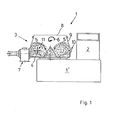
- a mixer of largely known type is shown and designated 1 overall.
- the mixer stands with a housing 1 'on the floor, which carries a control panel 2 and a container 3, in which a mixing tool 4 can rotate at a relatively high speed in such a way that the material contained in the container 3 executes a drum-shaped movement.
- This movement includes the outside rising of the material and falling back in an inner area according to the arrows 5 as well as the revolving with the mixing tool 4 around the container axis accordingly an arrow 6.
- an emptying device is indicated, as is customary in such containers in addition to various devices for supplying or removing materials, liquids, gases or for applying heat, vacuum, pressure, etc.
- the measuring device 10 is arranged at an angle of approximately 140 ° in front of a comminution tool 11 of a known type, which is likewise mounted in the lower region of the container casing 9 and projects into the container from the outside.
- the arrangement of the measuring device in front of the comminution tool namely at a distance from it, has proven to be advantageous, since the comminution tool influences the drum-shaped movement of the material to be mixed, this influence continuously decreasing along the circumference (in the direction of rotation of the mixing tool and the product), shortly before the shredding tool to rise again due to local repercussions.
- the mixing tool 10 is arranged at an angular distance of approximately 140 ° in front of the tool.
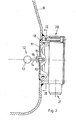
- an area of the container wall 9 can be seen in the enlarged representation, towards which a short sensor 12 with a spherical head 13 and a cylindrical neck 14 protrudes toward the interior of the container.
- This configuration is low in mass to respond to the impact of fine particles, they but is also sufficiently robust to withstand the impact of massive goods.
- the spherical head offers the material in the container a streamlined shape and therefore less susceptible to contamination, with the thinner neck 14 also suppressing contamination from sticking to the wall.
- the sensor 12 is fastened in the middle by means of a screw attachment 15 with wrench surfaces 16 in a deformable metal plate or membrane 17, the plate 17 - as will be seen from FIG. 3 - has a circular shape.
- the plate 17 is held flush on the edge side with respect to the container wall and carries a screw receptacle 18 in the middle for the sensor 12.
- the screw attachment enables the sensor to be replaced and sensors to be used in different sizes and / or dimensions, it can but also in favor of a fixed connection.
- strain gauges are arranged within a potting layer, which measure the deformations of the plate 17 and pass them on to an evaluation device, which is not shown but is basically known.
- This evaluation device is located in a separate housing from the container 3. Only the actual measuring device with a housing 20, which opens into a cable bushing 21, is located on the container.
- Fig. 3 shows a rear view of the deformable plate 17 with the more precise arrangement of strain gauges (but without their wiring).
- the circular plate 17 is divided with two mutually perpendicular diameter lines 22 and 23, along which strain gauges are arranged. A main direction is determined by the diameter line 22, on which four strain gauges 24, 25 and 26, 27 are arranged. These four strain gauge elements lie opposite one another in pairs on the same diameter, the strain gauges 24 and 26 and the strain gauges 25 and 27 being moved close together in order to be evaluated in pairs within a bridge circuit for temperature compensation.
- the strain gauge pairs experience different deformations and accordingly give opposite signal changes as a measure of the stress, the frequency characteristic of these strain gauges also passing on pulsed signals.
- strain gauges 28 and 29 are arranged diametrically opposite one another. These strain gauges do not respond when the sensor 12 experiences a stress in the direction of the diameter line 22, but only when at least one directional component of the stress falls on the diameter line 23. With such a configuration, it is possible to suppress changes in direction by assembling the stresses in a component-compatible manner. But it is also possible to determine the direction of the stress, which provides additional information about the movement of the mix in the container. This is also suitable and useful for the evaluation.
- the measuring device described despite its robustness, provides sensitive, constant monitoring of the mixed material in the container as long as it is being moved. This can be used to improve the monitoring of the mixed material which has already been used successfully, in particular in working processes in the pharmaceutical field, with high accuracy and reproducibility simple and expand to constant monitoring.
- the wall-flat arrangement with a low overall height and low sensor mass allows moving parts, including drives and controls, to be dispensed with, the arrangement in the lower part of the container with the possibility of measurement even when the container is only partially filled, and the need for special maintenance and inspection measures with regard to the container sealing in the area of the measuring device after there are no longer any movement gaps.
- the assembly and, if necessary, replacement of the measuring device is also simple, as can be seen from FIG. 2.
- the measuring device has a connector 30 projecting relative to the housing 20, which is inserted from the outside into a fastening ring 31 which is fixed to the container and is additionally sealed against this by means of an annular seal 32.
- Fastening screws 33 between the housing 20 and the fastening ring 31 secure the measuring device in its installed position, from which it can be removed at any time, be it for replacement or even for thorough cleaning.
Landscapes
- Chemical & Material Sciences (AREA)
- Health & Medical Sciences (AREA)
- Life Sciences & Earth Sciences (AREA)
- General Physics & Mathematics (AREA)
- Pathology (AREA)
- Analytical Chemistry (AREA)
- Biochemistry (AREA)
- General Health & Medical Sciences (AREA)
- Physics & Mathematics (AREA)
- Immunology (AREA)
- Chemical Kinetics & Catalysis (AREA)
- Engineering & Computer Science (AREA)
- Food Science & Technology (AREA)
- Medicinal Chemistry (AREA)
- Accessories For Mixers (AREA)
- Glanulating (AREA)
- Measurement Of Length, Angles, Or The Like Using Electric Or Magnetic Means (AREA)
- Artificial Filaments (AREA)
- Force Measurement Appropriate To Specific Purposes (AREA)
Applications Claiming Priority (2)
| Application Number | Priority Date | Filing Date | Title |
|---|---|---|---|
| DE3336218 | 1983-10-05 | ||
| DE3336218A DE3336218C2 (de) | 1983-10-05 | 1983-10-05 | Meßeinrichtung |
Publications (2)
| Publication Number | Publication Date |
|---|---|
| EP0136701A2 true EP0136701A2 (fr) | 1985-04-10 |
| EP0136701A3 EP0136701A3 (fr) | 1986-12-03 |
Family
ID=6211068
Family Applications (1)
| Application Number | Title | Priority Date | Filing Date |
|---|---|---|---|
| EP84111798A Withdrawn EP0136701A3 (fr) | 1983-10-05 | 1984-10-03 | Dispositif de mesure |
Country Status (4)
| Country | Link |
|---|---|
| US (1) | US4605172A (fr) |
| EP (1) | EP0136701A3 (fr) |
| JP (1) | JPS60155944A (fr) |
| DE (1) | DE3336218C2 (fr) |
Families Citing this family (8)
| Publication number | Priority date | Publication date | Assignee | Title |
|---|---|---|---|---|
| JPS6137629A (ja) * | 1984-07-30 | 1986-02-22 | Asahi Breweries Ltd | 軽粉粒体処理装置における詰り防止方法及びその装置 |
| DE3504860A1 (de) * | 1985-02-13 | 1986-08-14 | Dierks & Söhne GmbH & Co KG, 4500 Osnabrück | Verfahren und vorrichtung zur teigbereitung |
| DE4014361A1 (de) * | 1990-05-04 | 1991-11-14 | Werner & Pfleiderer | Temperatursensor fuer misch- und knetmaschinen |
| DE4401679C2 (de) * | 1994-01-21 | 1996-04-18 | Janke & Kunkel Kg | Rührgerät mit einer Haltevorrichtung |
| US5772128A (en) * | 1996-05-17 | 1998-06-30 | Csi Technology, Inc. | System for acoustically detecting and/or removing jams of flowable material in a chute, and air hammer for performing the removal |
| ITMI20051861A1 (it) * | 2005-10-04 | 2007-04-05 | Tycon Technoglass S R L | Contenitore di miscelazione per sostanze liquide o simili |
| JP5480836B2 (ja) * | 2011-03-24 | 2014-04-23 | 大成建設株式会社 | 分離装置 |
| US9101893B1 (en) * | 2014-03-17 | 2015-08-11 | Advanced Scientifics, Inc. | Mixing assembly and mixing method |
Family Cites Families (9)
| Publication number | Priority date | Publication date | Assignee | Title |
|---|---|---|---|---|
| GB1056161A (en) * | 1964-03-23 | 1967-01-25 | Fischer & Porter Ltd | Consistency measuring apparatus |
| US3382706A (en) * | 1965-10-12 | 1968-05-14 | Nat Metal Refining Company Inc | Oscillatory element for measuring viscosity |
| US3557616A (en) * | 1967-09-29 | 1971-01-26 | Combustion Eng | Particle flow sensing device |
| SU393643A1 (ru) * | 1972-04-05 | 1973-08-10 | Центральный научно исследовательский , проектный институт типового , экспериментального проектировани жилища | К АВТОРСКОМУ СВИДЕТЕЛЬСТВУМ. Кл. G 01п 11/12УДК 539.55.002.56(088.8) |
| FR2257083A1 (en) * | 1974-01-07 | 1975-08-01 | Ato Chimie | Detecting a change in the viscosity of moving fluid - by measuring the deformation of fixed element acted on by fluid |
| GB1564201A (en) * | 1975-11-27 | 1980-04-02 | Boots Co Ltd | Determining end point of agitating processes |
| DE2726228A1 (de) * | 1977-06-10 | 1978-12-14 | Karl H Ing Grad Kessler | Messfuehler zur kontinuierlichen erfassung der schmelzviskositaet stroemender kunststoffschmelzen |
| DE3008441A1 (de) * | 1980-03-05 | 1981-09-10 | Siemens AG, 1000 Berlin und 8000 München | Sensor zur druck-, kraft- bzw. beschleunigungs-messung |
| JPS5943216B2 (ja) * | 1981-06-23 | 1984-10-20 | 株式会社奈良機械製作所 | 混合・造粒・乾燥機 |
-
1983
- 1983-10-05 DE DE3336218A patent/DE3336218C2/de not_active Expired - Lifetime
-
1984
- 1984-10-01 US US06/656,629 patent/US4605172A/en not_active Expired - Lifetime
- 1984-10-03 EP EP84111798A patent/EP0136701A3/fr not_active Withdrawn
- 1984-10-04 JP JP59207257A patent/JPS60155944A/ja active Granted
Also Published As
| Publication number | Publication date |
|---|---|
| DE3336218A1 (de) | 1985-04-25 |
| EP0136701A3 (fr) | 1986-12-03 |
| JPS60155944A (ja) | 1985-08-16 |
| US4605172A (en) | 1986-08-12 |
| DE3336218C2 (de) | 1994-01-13 |
| JPH0414297B2 (fr) | 1992-03-12 |
Similar Documents
| Publication | Publication Date | Title |
|---|---|---|
| DE2706627A1 (de) | Vorrichtung zum messen der fliessgeschwindigkeit von pulvrigem und/oder koernigem material | |
| DE69422002T2 (de) | Dämpfungseinrichtung für einen Ultraschallflüssigkeitsniveauindikator | |
| DE2425732B2 (de) | Meß-und Dosiervorrichtung für fließfähige Materialien | |
| CH628735A5 (de) | Verfahren zur feuchtemessung fliessfaehigen materials und vorrichtung zur durchfuehrung des verfahrens. | |
| DE3336218C2 (de) | Meßeinrichtung | |
| EP3453459A1 (fr) | Procédé de fonctionnement d'une installation, installation et produit-programme informatique | |
| DE4136639C2 (de) | Vorrichtung zur elektrischen Ermittlung nicht gelöster Gase in mit Flüssigkeit gefüllten Hochspannungsanlagen und Geräten als Grundlage zur Fehlererkennung und Überwachung dieser Anlagen und Geräte | |
| DE1598522B2 (de) | Verfahren zur bestimmung des fettgehaltes von fleisch und wurstmassen | |
| DE2653864C3 (de) | Verfahren zur Bestimmung des Endpunktes eines Prozesses sowie Meßeinrichtung für die Durchführung eines solchen Verfahrens | |
| DE2845209A1 (de) | Vorrichtung zur messung der auf zwei achsen bezogenen traegheitsmomente eines geraets | |
| DE2846668A1 (de) | Dehnungsmesseinrichtung fuer schraubenspannvorrichtungen, insbesondere bei reaktordruckbehaeltern | |
| DE3833896C2 (fr) | ||
| EP3514509B1 (fr) | Capteur de surveillance pour quantités de poudre dosées | |
| DE3113785A1 (de) | Verfahren und vorrichtung zur bestimmung der konsistenz von angemachtem beton | |
| EP1063016B1 (fr) | Procédé et dispositif de mesure du niveau de remplissage d'une centrifugeuse filtrante | |
| EP4105615B1 (fr) | Procédé de dosage pour unités posologiques et utilisation d'une vanne doseuse dans un dispositif d'étalonnage pour un système de mesure capacitif | |
| DE8632565U1 (de) | Leckwarneinrichtung | |
| DE102022127532A1 (de) | Eigenschaftsbestimmung von Schüttgut | |
| DE1121378B (de) | Verfahren zur kontinuierlichen Bestimmung des Wasseranteils in pulvrigen und koernigen Schuettguetern durch Messung der Dielektrizitaetskonstanten | |
| DE2017176C3 (de) | Vorrichtung zur automatischen Bestimmung der spezifischen Oberfläche von pulverförmiger! Substanzen | |
| DE102016215164A1 (de) | Messvorrichtung zur Bestimmung des Verschleißes eines Innenmischers | |
| DE102025117039A1 (de) | Testgerät zum Vermessen von kleinvolumigem Schüttgut | |
| DE1598522C (de) | Verfahren zur Bestimmung des Fettgehal tes von Fleisch und Wurstmassen | |
| DE2314670C2 (de) | Rotationsrheometer | |
| AT162847B (de) | Verfahren und Vorrichtung zum Vorausbestimmen des Verhaltens einer Betonmischung |
Legal Events
| Date | Code | Title | Description |
|---|---|---|---|
| PUAI | Public reference made under article 153(3) epc to a published international application that has entered the european phase |
Free format text: ORIGINAL CODE: 0009012 |
|
| AK | Designated contracting states |
Designated state(s): AT BE CH DE FR GB IT LI NL SE |
|
| RTI1 | Title (correction) | ||
| PUAL | Search report despatched |
Free format text: ORIGINAL CODE: 0009013 |
|
| AK | Designated contracting states |
Kind code of ref document: A3 Designated state(s): AT BE CH DE FR GB IT LI NL SE |
|
| 17P | Request for examination filed |
Effective date: 19870205 |
|
| 17Q | First examination report despatched |
Effective date: 19880615 |
|
| STAA | Information on the status of an ep patent application or granted ep patent |
Free format text: STATUS: THE APPLICATION HAS BEEN WITHDRAWN |
|
| 18W | Application withdrawn |
Withdrawal date: 19890606 |
|
| R18W | Application withdrawn (corrected) |
Effective date: 19890606 |
|
| RIN1 | Information on inventor provided before grant (corrected) |
Inventor name: AHLERT, DIETER |