EP0136618A2 - Blechprofilstab für Traggerippe von zweischaligen Trennwänden - Google Patents
Blechprofilstab für Traggerippe von zweischaligen Trennwänden Download PDFInfo
- Publication number
- EP0136618A2 EP0136618A2 EP84111116A EP84111116A EP0136618A2 EP 0136618 A2 EP0136618 A2 EP 0136618A2 EP 84111116 A EP84111116 A EP 84111116A EP 84111116 A EP84111116 A EP 84111116A EP 0136618 A2 EP0136618 A2 EP 0136618A2
- Authority
- EP
- European Patent Office
- Prior art keywords
- profile
- web surface
- sheet metal
- wall shells
- openings
- Prior art date
- Legal status (The legal status is an assumption and is not a legal conclusion. Google has not performed a legal analysis and makes no representation as to the accuracy of the status listed.)
- Withdrawn
Links
Images
Classifications
-
- E—FIXED CONSTRUCTIONS
- E04—BUILDING
- E04C—STRUCTURAL ELEMENTS; BUILDING MATERIALS
- E04C2/00—Building elements of relatively thin form for the construction of parts of buildings, e.g. sheet materials, slabs, or panels
- E04C2/30—Building elements of relatively thin form for the construction of parts of buildings, e.g. sheet materials, slabs, or panels characterised by the shape or structure
- E04C2/34—Building elements of relatively thin form for the construction of parts of buildings, e.g. sheet materials, slabs, or panels characterised by the shape or structure composed of two or more spaced sheet-like parts
-
- E—FIXED CONSTRUCTIONS
- E04—BUILDING
- E04B—GENERAL BUILDING CONSTRUCTIONS; WALLS, e.g. PARTITIONS; ROOFS; FLOORS; CEILINGS; INSULATION OR OTHER PROTECTION OF BUILDINGS
- E04B2/00—Walls, e.g. partitions, for buildings; Wall construction with regard to insulation; Connections specially adapted to walls
- E04B2/74—Removable non-load-bearing partitions; Partitions with a free upper edge
- E04B2/76—Removable non-load-bearing partitions; Partitions with a free upper edge with framework or posts of metal
- E04B2/78—Removable non-load-bearing partitions; Partitions with a free upper edge with framework or posts of metal characterised by special cross-section of the frame members as far as important for securing wall panels to a framework with or without the help of cover-strips
- E04B2/7854—Removable non-load-bearing partitions; Partitions with a free upper edge with framework or posts of metal characterised by special cross-section of the frame members as far as important for securing wall panels to a framework with or without the help of cover-strips of open profile
- E04B2/789—Removable non-load-bearing partitions; Partitions with a free upper edge with framework or posts of metal characterised by special cross-section of the frame members as far as important for securing wall panels to a framework with or without the help of cover-strips of open profile of substantially U- or C- section
-
- E—FIXED CONSTRUCTIONS
- E04—BUILDING
- E04B—GENERAL BUILDING CONSTRUCTIONS; WALLS, e.g. PARTITIONS; ROOFS; FLOORS; CEILINGS; INSULATION OR OTHER PROTECTION OF BUILDINGS
- E04B2/00—Walls, e.g. partitions, for buildings; Wall construction with regard to insulation; Connections specially adapted to walls
- E04B2/74—Removable non-load-bearing partitions; Partitions with a free upper edge
- E04B2/7407—Removable non-load-bearing partitions; Partitions with a free upper edge assembled using frames with infill panels or coverings only; made-up of panels and a support structure incorporating posts
- E04B2/7409—Removable non-load-bearing partitions; Partitions with a free upper edge assembled using frames with infill panels or coverings only; made-up of panels and a support structure incorporating posts special measures for sound or thermal insulation, including fire protection
- E04B2/7412—Posts or frame members specially adapted for reduced sound or heat transmission
Definitions
- the invention relates to a sheet metal profile bar for supporting skeletons of double-skin partition walls, with at least two profile flange surfaces which can each be connected to opposite wall shells of the partition wall and which are connected to one another by a profile web surface which is designed to be elastic in the normal direction of the wall shells.
- Sheet metal profile bars with different profile shapes are used for the support structure of double-skin partitions. Frequently, these sheet metal profile bars have a C-profile or a U-profile, the web surface extending between the two wall shells and connecting them to one another. The transmission of vibrations, in particular sound vibrations, between the two wall shells takes place for the most part through these profile web surfaces.
- the heat transfer between the two wall shells is unchanged compared to a conventional C-profile or U-profile in this design of the profile web surface which is obtuse in cross section.
- thermal insulation boards are usually inserted into the space between the two wall shells.
- the thermal bridges or cold bridges formed by the profile web surfaces remain and make the insulation effect of the inserted insulation panels at least partially ineffective again.
- the object of the invention is therefore to design a sheet metal profile rod of the type mentioned in such a way that a substantial reduction in the heat transfer between the two adjacent wall shells is achieved without a significant reduction in its rigidity while at the same time improving the sound insulation.
- the profile web surface has a plurality of longitudinal rows of openings which extend essentially in the longitudinal direction of the profile bar and are offset with respect to one another.
- the material webs delimiting the openings essentially extend in the longitudinal direction of the profile, they are only subjected to bending under the forces acting in the normal direction of the wall panels, that is to say also by vibrations of the wall panels, so that the profile web surface is very elastic in this normal direction of the wall panels is. As a result, sound vibrations are transmitted very little.
- the profile web surface is therefore neither a thermal bridge nor a sound bridge.
- the profile web surface is designed as an expanded metal field has proven to be particularly favorable in this regard.
- the perforations are elongated diamonds, so that the remaining webs of material run obliquely to the longitudinal direction of the section bar.
- the web grating formed from these inclined material webs is for absorbing shear stresses particularly suitable, so that a high rigidity of the profile web surface is maintained.
- the design of the profile web surface as an expanded metal field has the further advantage that the perforations are made by tearing without waste of material, i. H. by cutting and pulling apart the cut edges.
- the sheet metal strip required for the production of the web surface is therefore considerably narrower than the openwork profile web surface formed therefrom.
- the openings in the profile web surface can be designed as longitudinal slots
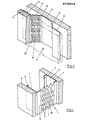
- the sheet metal profile bar 1 shown in FIG. 1 with a C cross section has a profile web surface 2, from the two longitudinal edges of which profile flange surfaces 3 and 4 extend at right angles in the same direction. The free edges of the profile flange surfaces are angled to mutually directed edge strips 5 and 6.
- Such Sheet metal profile bars 1 are used to build support ribs for double-skin partitions, wall shells 7, 8 being attached to the two profile flange surfaces 3 and 4, respectively.
- the profile web surface 2 is designed as an expanded metal field. Several longitudinal rows of approximately diamond-shaped openings 9 extending essentially in the longitudinal direction of the profile bar have been created by cutting and tearing the sheet metal in the region of the profile web surface 2.
- the openings 9 of adjacent longitudinal rows are offset from one another.
- the webs 10 which have remained between the openings 9 run obliquely to the longitudinal direction of the section bar and form a grid which, however, has no webs running in the normal direction of the wall shells 7, 8 and connecting them.
- the profile web surface 2 is therefore very elastic in this normal direction, so that vibrations, for example sound vibrations, are only transmitted to a very small extent.
- the heat transfer between the two flange profile 3 and 4 via the profile web surface 2 is thereby greatly reduced, that the e W g is very large for the heat transfer through the zigzag-shaped course of the webs 10th
- the material cross section of the webs 10 is small.
- a modified embodiment is shown as a sheet metal profile bar 11 in FIG. 2.
- the sheet metal profile rod 11 has two opposing profile flange surfaces 13 arranged in a common plane as edge strips, which are each connected in one piece via an inclined profile web surface 12 to a common profile flange surface 14 lying in the middle of the sheet metal profile rod 11.
- the two profile flange surfaces 13 are connected to one wall shell 17 and the other profile flange surface 14 is connected to the other wall shell 18.
- the profile web surfaces 12 also have openings 19, which are designed as a plurality of longitudinal rows of mutually offset longitudinal slots. Between the adjacent rows of longitudinal slots 19 there remain material webs 20 which extend in the longitudinal direction of the profile bar and act as elastic bending beams when forces are transmitted in the normal direction to the wall shells 17, 18, in particular when transmitting vibrations. As in the embodiment of FIG. 1, the path for heat transfer between the profile flange surfaces 13 and 14 is also relatively long, while the material cross section available for this is small.
- Both of the exemplary embodiments shown have in common that the formation of thermal bridges or cold bridges in the area of the sheet-metal profile bars of the supporting structure of a partition wall is prevented by the substantial reduction in the heat-conducting possibilities. At the same time, the fire protection effect is improved because the high temperature that occurs in the event of fire on one side of the partition does not transfer to the other side of the wall.
- the two profile shapes shown are only examples from numerous examples Possible designs. It goes without saying that the design of the profile web surface as an expanded metal field, which was shown in FIG. 1, can also be used with a profile cross section according to FIG. 2 and vice versa. Other profile cross sections are also possible, provided that they only have one thing in common that they have a profile web surface connecting the two wall shells.
Landscapes
- Engineering & Computer Science (AREA)
- Architecture (AREA)
- Civil Engineering (AREA)
- Structural Engineering (AREA)
- Physics & Mathematics (AREA)
- Electromagnetism (AREA)
- Building Environments (AREA)
- Heat Treatments In General, Especially Conveying And Cooling (AREA)
- Finishing Walls (AREA)
Abstract
© Ein Blechprofilstab (1) weist gegenüberliegende Profil-Flanschflächen (3, 4) auf, die jeweils mit gegenüberliegenden Wandschalen (7, 8) einer zweischaligen Trennwand verbunden sind. Die beiden Profil-Flanschflächen (3, 4) sind miteinander durch eine Profil-Stegfläche (2) verbunden, die mehrere Längsreihen von Durchbrechungen (9) aufweist. Die Durchbrechungen (9) erstrecken sich in Profilstab-Längsrichtung und sind in den benachbarten Längsreihen gegeneinander versetzt. Dadurch entsteht ein Gitter von Materialstegen (10), die schräg zur Profilstab-Längsrichtung verlaufen. Die Profil-Stegfläche (2) ist in der Normalrichtung der Wandschalen (7, 8) elastisch, so daß die Schwingungsübertragung zwischen den Wandschalen (7, 8) gegenüber einer vollflächigen Stegfläche herabgesetzt ist. Außerdem ist die Wärmeübertragung zwischen den beiden Wandschalen (7, 8) wesentlich vermindert, weil der Querschnitt der Materialstege (10) gering ist und weil der von den Materialstegen (10) vorgegebene Weg für die Wärmeleitung verhältnismäßig lang ist.
Description
- Die Erfindung betrifft einen Blechprofilstab für Traggerippe von zweischaligen Trennwänden, mit mindestens zwei jeweils mit gegenüberliegenden Wandschalen der Trennwand verbindbaren Profil-Flanschflächen, die durch eine Profil-Stegfläche miteinander verbunden sind, die in der Normalrichtung der Wandschalen elastisch ausgeführt ist.
- Für die Traggerippe von zweischaligen Trennwänden werden Blechprofilstäbe mit unterschiedlicher Profilgestalt verwendet. Häufig haben diese Blechprofilstäbe ein C-Profil oder ein U-Profil, wobei sich die Stegfläche jeweils zwischen den beiden Wandschalen erstreckt.und diese miteinander verbindet. Die Übertragung von Schwingungen, insbesondere Schallschwingungen, zwischen den beiden Wandschalen erfolgt zum allergrößten Teil durch diese Profil-Stegflächen.
- Um eine gute Schallisolierung der Trennwand zu erreichen, d. h. eine möglichst geringe Übertragung von Schwingungen zwischen den beiden Wandschalen, wurde bei einem bekannten Blechprofilstab der eingangs genannten Gattung (DE-PS 1 122 686) vorgesehen, die Profil-Stegfläche im Querschnitt stumpfwinklig auszuführen, so daß sie in Normalrichtung der Wandschalen wesentlich elastischer ist als eine sich geradlinig zwischen den beiden Wandschalen erstreckende Stegfläche.
- Die Wärmeübertragung zwischen den beiden Wandschalen ist jedoch bei dieser im Querschnitt stumpfwinkligen Ausführung der Profil-Stegfläche unverändert gegenüber einem herkömmlichen C-Profil oder U-Profil. Zur Wärmedämmung werden zwar in den zwischen den beiden Wandschalen befindlichen Raum üblicherweise Wärmedämmplatten eingelegt. Die durch die Profil-Stegflächen gebildeten Wärmebrücken bzw. Kältebrücken bleiben jedoch bestehen und machen die Dämmwirkung der eingelegten Dämmplatten mindestens teilweise wieder unwirksam.
- Aufgabe der Erfindung ist es daher, einen Blechprofilstab der eingangs genannten Gattung so auszubilden, daß ohne wesentliche Verringerung seiner Steifigkeit eine wesentliche Verringerung der Wärmeübertragung zwischen den beiden benachbarten Wandschalen unter gleichzeitiger Verbesserung der Schallisolierung erreicht wird.
- Diese Aufgabe wird erfindungsgemäß dadurch gelöst, daß die Profil-Stegfläche mehrere Längsreihen von sich im wesentlichen in Profilstab-Längsrichtung erstreckenden, gegeneinander versetzten Durchbrechungen aufweist.
- Durch diese sich in Längsrichtung des Profilstabs erstreckenden Durchbrechungen wird nicht nur der Querschnitt der die Wärmeleitung bewirkenden Wärmebrücke zwischen den beiden Profil-Flanschflächen erreicht, sondern insbesondere auch eine Vergrößerung der wirksamen Länge der Wärmebrücke auf einen Wert, der das Mehrfache des Abstands der Profil-Flanschflächen beträgt. Beide Faktoren vermindern die Wärmeleitung zwischen den beiden Profil-Flanschflächen in erheblichem Umfang.
- Da die die Durchbrechungen begrenzenden Materialstege sich im wesentlichen in Profil-Längsrichtung erstrecken, werden sie bei in Normalrichtung der Wandplatten wirkenden Kräften, also auch durch Schwingungen der Wandplatten, nur auf Biegung beansprucht, so daß die Profil-Stegfläche in dieser Normalrichtung der Wandschalen sehr elastisch ist. Dadurch werden Schallschwingungen nur sehr wenig übertragen. Die Profil-Stegfläche stellt daher weder eine Wärmebrücke noch eine Schallbrücke dar.
- Da die Steifigkeit der Profil-Stegfläche im wesentlichen durch die aufzunehmenden Schubbeanspruchungen bestimmt wird, wird diese Steifigkeit gegenüber einer vollflächigen Ausführung nur geringfügig herabgesetzt, da sich die verbleibenden Materialstege überwiegend in Richtung der Schubbeanspruchung erstrecken.
- Als besonders günstig hat sich in dieser Hinsicht eine Ausführungsform der Erfindung erwiesen, bei der die Profil-Stegfläche als Streckmetallfeld ausgeführt ist. In einem solchen Streckmetallfeld sind die Durchbrechungen längliche Rauten, so daß die verbleibenden Materialstege schräg zur Profilstab-Längsrichtung verlaufen. Das aus diesen schrägverlaufenden Materialstegen gebildete Steggitter ist zur Aufnahme von Schubbeanspruchungen besonders geeignet, so daß eine hohe Steifigkeit der Profilstegfläche erhalten bleibt.
- Die Ausführung der Profilstegfläche als Streckmetallfeld hat den weiteren Vorteil, daß die Durchbrechungen ohne Materialabfall durch Aufreißen hergestellt werden, d. h. durch Einschneiden und Auseinanderziehen der Einschnittränder. Der für die Herstellung der Stegfläche benötigten Blechstreifen ist daher wesentlich schmaler als die daraus gebildete, durchbrochene Profil-Stegfläche.
- Gemäß einer anderen Ausführungsform des Erfindungsgedankens können die Durchbrechungen der Profil-Stegfläche als Längsschlitze ausgeführt sein,
- Die Erfindung wird nachfolgend an Ausführungsbeispielen näher erläutert, die in der Zeichnung dargestellt sind. Es zeigt:
- Fig. 1 in perspektivischer Darstellungsweise einen Abschnitt eines Blechprofilstabs mit C-förmigem Querschnitt zwischen zwei Wandschalen und
- Fig. 2 in einer Darstellung entsprechend der Fig. 1 einen Blechprofilstab mit Trapezquerschnitt.
- Der in Fig. 1 gezeigte Blechprofilstab 1 mit C-Querschnitt weist eine Profil-Stegfläche 2 auf, von deren beiden Längsrändern sich Profil-Flanschflächen 3 und 4 rechtwinklig in derselben Richtung erstrecken. Die freien Ränder der Profil-Flanschflächen sind zu gegeneinander gerichteten Randstreifen 5 bzw. 6 abgewinkelt. Derartige Blechprofilstäbe 1 dienen zum Aufbau von Traggerippen für zweischalige Trennwände, wobei Wandschalen 7, 8 an den beiden Profil-Flanschflächen 3 bzw. 4 angebracht werden.
- Die Profil-Stegfläche 2 ist als Streckmetallfeld ausgeführt. Mehrere Längsreihen von sich im wesentlichen in Profilstab-Längsrichtung erstreckenden, angenähert rautenförmigen Durchbrechungen 9 sind durch Einschneiden und Aufreißen des Blechs im Bereich der Profil-Stegfläche 2 entstanden.
- Die Durchbrechungen 9 benachbarter Längsreihen sind gegeneinander versetzt. Die zwischen den Durchbrechungen 9 stehengebliebenen Stege 10 verlaufen schräg zur Profilstab-Längsrichiung und bilden ein Gitter, das jedoch keine in Normalrichtung der Wandschalen 7, 8 verlaufenden und diese verbindenden Stege aufweist. Die Profil-Stegfläche 2 ist daher in dieser Normalrichtung sehr elastisch, so daß Schwingungen, beispielsweise Schallschwingungen, nur in sehr geringem Maße übertragen werden. Die Wärmeübertragung zwischen den beiden Profil-Flanschflächen 3 und 4 über die Profil-Stegfläche 2 ist dadurch stark vermindert, daß der Weg für die Wärmeübertragung durch den zick-zack-förmigen Verlauf der Stege 10 sehr groß ist. Außerdem ist der Materialquerschnitt der Stege 10 gering.
- Eine abgewandelte Ausführungsform ist als Blechprofilstab 11 in Fig. 2 dargestellt. Der Blechprofilstab 11 weist zwei gegenüberliegende, in einer gemeinsamen Ebene angeordneten Profil-Flanschflächen 13 als Randstreifen auf, die jeweils über eine schräg dazu verlaufende Profil- Stegfläche 12 mit einer gemeinsamen, in der Mitte des Blechprofilstabs 11 liegenden Profil-Flanschfläche 14 einstückig verbunden sind. Die beiden Profil-Flanschflächen 13 sind mit der einen Wandschale 17 und die andere Profil-Flanschfläche 14 ist mit der anderen Wandschale 18 verbunden.
- Die Profil-Stegflächen 12 weisen auch hierbei Durchbrechungen 19 auf, die als mehrere Längsreihen von gegeneinander versetzten Längsschlitzen ausgeführt sind. Zwischen den benachbarten Reihen von Längsschlitzen 19 bleiben Materialstege 20 bestehen, die sich in Profilstab-Längsrichtung erstrecken und bei der Übertragung von Kräften in Normalrichtung zu den Wandschalen 17, 18, insbesondere bei der Schwingungsübertragung, als elastische Biegebalken wirken. Ebenso wie beim Ausführungsbeispiel nach Fig. 1 ist auch hierbei der Weg für eine Wärmeübertragung zwischen den Profil-Flanschflächen 13 und 14 verhältnismäßig lang, während der hierfür zur Verfügung stehende Materialquerschnitt gering ist.
- Beiden dargestellten Ausführungsbeispielen ist gemeinsam, daß durch die wesentliche Verringerung der Wärmeleitmöglichkeiten die Bildung von Wärmebrücken bzw. Kältebrücken im Bereich der Blechprofilstäbe des Traggerippes einer Trennwand verhindert wird. Zugleich wird dadurch die Brandschutzwirkung verbessert, weil sich die im Brandfall auf einer Seite der Trennwand auftretende hohe Temperatur nicht auf die andere Wandseite überträgt.
- Die beiden dargestellten Profilformen stellen nur zur Erläuterung herausgegriffene Beispiele aus zahlreichen Ausführungsmöglichkeiten dar. Es versteht sich, daß die Ausführung der Profil-Stegfläche als Streckmetallfeld, die in Fig. 1 gezeigt wurde, auch bei einem Profilquerschnitt nach Fig. 2 verwendet werden kann und umgekehrt. Auch sonstige Profilquerschnitte sind möglich, sofern diesen nur gemeinsam ist, daß sie eine die beiden Wandschalen verbindende Profil-Stegfläche aufweisen.
Claims (3)
1. Blechprofilstab für Traggerippe von zweischaligen Trennwänden, mit mindestens zwei jeweils mit gegenüberliegenden Wandschalen der Trennwand verbindbaren Profil-Flanschflächen, die durch eine Profil-Stegfläche miteinander verbunden sind, die in der Normalrichtung der Wandschalen elastisch ausgeführt ist, dadurch gekennzeichnet, daß die Profil-Stegfläche (2, 12) mehrere Längsreihen von sich im wesentlichen in Profilstab-Längsrichtung erstreckenden, gegeneinander versetzten Durchbrechungen (9, 19) aufweist.
2. Blechprofilstab nach Anspruch 1, dadurch gekennzeichnet, daß die Profil-Stegfläche (2) als Streckmetallfeld ausgeführt ist.
3. Blechprofilstab nach Anspruch 1, dadurch gekennzeichnet, daß die Durchbrechungen (19) der Profil- Stegfläche (12) Längsschlitze sind..
Applications Claiming Priority (2)
| Application Number | Priority Date | Filing Date | Title |
|---|---|---|---|
| DE19833336378 DE3336378A1 (de) | 1983-10-06 | 1983-10-06 | Blechprofilstab fuer traggerippe von zweischaligen trennwaenden |
| DE3336378 | 1983-10-06 |
Publications (2)
| Publication Number | Publication Date |
|---|---|
| EP0136618A2 true EP0136618A2 (de) | 1985-04-10 |
| EP0136618A3 EP0136618A3 (de) | 1986-05-14 |
Family
ID=6211168
Family Applications (1)
| Application Number | Title | Priority Date | Filing Date |
|---|---|---|---|
| EP84111116A Withdrawn EP0136618A3 (de) | 1983-10-06 | 1984-09-18 | Blechprofilstab für Traggerippe von zweischaligen Trennwänden |
Country Status (2)
| Country | Link |
|---|---|
| EP (1) | EP0136618A3 (de) |
| DE (1) | DE3336378A1 (de) |
Cited By (18)
| Publication number | Priority date | Publication date | Assignee | Title |
|---|---|---|---|---|
| AT1457U3 (de) * | 1995-02-17 | 1997-11-25 | Huenting Harald Dipl Ing | Vorrichtung zur befestigung einer strebe an einem rohbauuntergrund |
| WO1998022670A1 (en) * | 1996-11-20 | 1998-05-28 | Lamminmaeki Pauli | Bracing truss for concrete or masoned structural layers and method for manufacturing the same |
| WO2000034594A1 (en) * | 1998-12-11 | 2000-06-15 | Owens Corning | Resilient construction member |
| EP1074671A3 (de) * | 1999-07-21 | 2001-02-14 | Profil-Vertrieb GmbH | Als Leichtbauprofil ausgebildetes Ständerprofil |
| WO2001042582A1 (en) * | 1999-12-07 | 2001-06-14 | Dallan S.R.L. | Method for producing metal profile bars for support structures for panels, particularly of plaster-board, and profile bar produced by the method |
| WO2002006600A1 (de) * | 2000-07-18 | 2002-01-24 | Richter-System Gmbh & Co. Kg | Tragprofil |
| EP1312725A1 (de) | 2001-11-19 | 2003-05-21 | Rautaruukki OYJ | Aussenwandpaneel und Aussenwand |
| GB2346394B (en) * | 1999-01-14 | 2003-07-09 | Tackburn Ltd | Spacing Member |
| US6615559B2 (en) | 1998-12-11 | 2003-09-09 | Owens Corning Fiberglas Technology, Inc. | Resilient construction member, especially a unitary construction member |
| EP1543202A4 (de) * | 2002-08-05 | 2006-03-29 | Jeffrey A Anderson | Metallrahmenglied und herstellungsverfahren |
| WO2007042525A3 (en) * | 2005-10-12 | 2007-05-31 | Dallan Spa | Profile for plaster board walls and accessory for its fixing to the ceiling |
| EP1992752A3 (de) * | 2007-04-26 | 2012-06-27 | Illinois Tool Works Inc. | Verbesserungen an oder im Zusammenhang mit Bauteilen |
| EP2024578A4 (de) * | 2006-06-02 | 2014-04-30 | Rautaruukki Oyj | Aussenwand eines gebäudes und metallwabenstruktur zur verwendung darin |
| US8763347B2 (en) | 2010-02-01 | 2014-07-01 | Jeffrey A. Anderson | Apparatus for manufacturing a metal framing member |
| US9174264B2 (en) | 2003-08-05 | 2015-11-03 | Jeffrey A. Anderson | Method of manufacturing a metal framing member |
| WO2016001580A1 (fr) * | 2014-07-03 | 2016-01-07 | Groupe Bacacier | Écarteur a rupture de pont thermique pour dispositif de construction, son utilisation et dispositif de construction correspondant |
| WO2018147743A1 (en) * | 2017-02-07 | 2018-08-16 | Hunton Fiber As | Sound insulating building construction element |
| CN110029754A (zh) * | 2019-04-26 | 2019-07-19 | 湖南坚致幕墙安装设计有限公司 | 组合型框架系统 |
Families Citing this family (3)
| Publication number | Priority date | Publication date | Assignee | Title |
|---|---|---|---|---|
| DE3825566A1 (de) * | 1988-07-28 | 1990-02-01 | Plan Object Gmbh | Profilkombination fuer staender und kaempfer der unterkonstruktion einer trennwand |
| DE19950890C1 (de) * | 1999-10-22 | 2001-10-31 | Thomas Hengst | Ständerprofilstab zur Errichtung von Trockenbauwänden |
| DE10259304A1 (de) * | 2002-12-18 | 2004-08-26 | Protektorwerk Florenz Maisch Gmbh & Co Kg | Ständerprofil |
Family Cites Families (3)
| Publication number | Priority date | Publication date | Assignee | Title |
|---|---|---|---|---|
| DE1559507A1 (de) * | 1965-12-03 | 1969-11-06 | Bauakademie Ddr | Zweischalige Leichtbauplatte |
| SE394478B (sv) * | 1974-10-16 | 1977-06-27 | Interoc Fasad Ab | Profilskena av tunnplat for anvendning sasom distanshallande, forstyvande och belastningsupptagande konstruktionselement i vermeisolerade byggnadsdelar |
| US3940899A (en) * | 1975-05-27 | 1976-03-02 | United States Gypsum Company | Stud having struck-out flanges and fire-rated wall structure formed therewith |
-
1983
- 1983-10-06 DE DE19833336378 patent/DE3336378A1/de not_active Withdrawn
-
1984
- 1984-09-18 EP EP84111116A patent/EP0136618A3/de not_active Withdrawn
Cited By (23)
| Publication number | Priority date | Publication date | Assignee | Title |
|---|---|---|---|---|
| AT1457U3 (de) * | 1995-02-17 | 1997-11-25 | Huenting Harald Dipl Ing | Vorrichtung zur befestigung einer strebe an einem rohbauuntergrund |
| WO1998022670A1 (en) * | 1996-11-20 | 1998-05-28 | Lamminmaeki Pauli | Bracing truss for concrete or masoned structural layers and method for manufacturing the same |
| US6711867B1 (en) * | 1998-12-11 | 2004-03-30 | Owens Corning Fiberglas Technology, Inc. | Self-jigging resilient construction member and retrofit system using same |
| WO2000034594A1 (en) * | 1998-12-11 | 2000-06-15 | Owens Corning | Resilient construction member |
| US6755003B1 (en) * | 1998-12-11 | 2004-06-29 | Owens Corning Fiberglas Technology, Inc. | Resilient construction member |
| US6615559B2 (en) | 1998-12-11 | 2003-09-09 | Owens Corning Fiberglas Technology, Inc. | Resilient construction member, especially a unitary construction member |
| AU765998B2 (en) * | 1998-12-11 | 2003-10-09 | Owens Corning Intellectual Capital, Llc | Resilient construction member |
| GB2346394B (en) * | 1999-01-14 | 2003-07-09 | Tackburn Ltd | Spacing Member |
| EP1074671A3 (de) * | 1999-07-21 | 2001-02-14 | Profil-Vertrieb GmbH | Als Leichtbauprofil ausgebildetes Ständerprofil |
| US6381916B1 (en) | 1999-07-21 | 2002-05-07 | Profil-Vertrieb Gmbh | Upright construction section |
| WO2001042582A1 (en) * | 1999-12-07 | 2001-06-14 | Dallan S.R.L. | Method for producing metal profile bars for support structures for panels, particularly of plaster-board, and profile bar produced by the method |
| WO2002006600A1 (de) * | 2000-07-18 | 2002-01-24 | Richter-System Gmbh & Co. Kg | Tragprofil |
| EP1312725A1 (de) | 2001-11-19 | 2003-05-21 | Rautaruukki OYJ | Aussenwandpaneel und Aussenwand |
| EP1543202A4 (de) * | 2002-08-05 | 2006-03-29 | Jeffrey A Anderson | Metallrahmenglied und herstellungsverfahren |
| US9174264B2 (en) | 2003-08-05 | 2015-11-03 | Jeffrey A. Anderson | Method of manufacturing a metal framing member |
| WO2007042525A3 (en) * | 2005-10-12 | 2007-05-31 | Dallan Spa | Profile for plaster board walls and accessory for its fixing to the ceiling |
| EP2024578A4 (de) * | 2006-06-02 | 2014-04-30 | Rautaruukki Oyj | Aussenwand eines gebäudes und metallwabenstruktur zur verwendung darin |
| EP1992752A3 (de) * | 2007-04-26 | 2012-06-27 | Illinois Tool Works Inc. | Verbesserungen an oder im Zusammenhang mit Bauteilen |
| US8763347B2 (en) | 2010-02-01 | 2014-07-01 | Jeffrey A. Anderson | Apparatus for manufacturing a metal framing member |
| WO2016001580A1 (fr) * | 2014-07-03 | 2016-01-07 | Groupe Bacacier | Écarteur a rupture de pont thermique pour dispositif de construction, son utilisation et dispositif de construction correspondant |
| FR3023310A1 (fr) * | 2014-07-03 | 2016-01-08 | Groupe Bacacier | Ecarteur a rupture de pont thermique pour dispositif de construction, son utilisation et dispositif de construction correspondant |
| WO2018147743A1 (en) * | 2017-02-07 | 2018-08-16 | Hunton Fiber As | Sound insulating building construction element |
| CN110029754A (zh) * | 2019-04-26 | 2019-07-19 | 湖南坚致幕墙安装设计有限公司 | 组合型框架系统 |
Also Published As
| Publication number | Publication date |
|---|---|
| EP0136618A3 (de) | 1986-05-14 |
| DE3336378A1 (de) | 1985-05-02 |
Similar Documents
| Publication | Publication Date | Title |
|---|---|---|
| EP0136618A2 (de) | Blechprofilstab für Traggerippe von zweischaligen Trennwänden | |
| EP0652332B1 (de) | Wärmedämmplatte aus Faserdämmstoff oder Kork | |
| DE69711573T2 (de) | Stütze für Trägerkanäle | |
| DE69802912T2 (de) | Decken oder wandprofil | |
| DE2546235A1 (de) | Blechriegelschiene zum aufbau von waermeisolierenden bauteilen | |
| DE2429916A1 (de) | Vorrichtung an schalldaemmenden waenden | |
| DE1684795B2 (de) | Raumkasten mit Betonwandungen, die von Metall-Profilbalken eingefaßt sind | |
| DE3442355C1 (de) | Blechprofil für Unterdeckenträger, Ständer u. dgl. | |
| DE2902831A1 (de) | Schall- und waermeisolationswand | |
| EP0196672A2 (de) | Paneele zur Verkleidung von Aussenwänden von Gebäuden | |
| DE4400682A1 (de) | Schiene mit Feuerklassifizierung für Hängedecken | |
| DE3419734A1 (de) | Luftgekuehlter oberflaechenkondensator | |
| DE2206973C3 (de) | Räumliches Bauelement zur Bildung von Trag- und Stützwerken | |
| EP0005427A2 (de) | Verbesserter Ständer für Hohlwände und dergleichen | |
| EP0834622A2 (de) | Wärmegedämmtes Verbindungselement zwischen externen Betonteilen, insbesondere Kragplatten, und Gebäude | |
| EP0430921A1 (de) | Wand, die aus kastenförmigen Plattenelementen besteht | |
| EP0277256A1 (de) | Nagelplatte | |
| DE1961701C3 (de) | Wetterfestes Lufteinlaßgitter | |
| DE69516956T2 (de) | Modularer Umfassungs-Satz zum Abgrenzen eines erweiterbaren, umschlossenen Rauminhaltes | |
| DE1759648A1 (de) | Vorgefertigte Wand | |
| DE3231487A1 (de) | Staenderprofil fuer zweischalige waende | |
| AT410238B (de) | Verfahren zur herstellung von verbundprofilen mit durch wärmeisolierende zwischenstege mechanisch verbundenen metallseitenteilen | |
| DE3321758C2 (de) | Halteleiste für im Abstand voneinander zu verlegende Rohre | |
| DE191723C (de) | ||
| DE2334860C3 (de) | Zur Bildung von Regalen dienende Trennwand |
Legal Events
| Date | Code | Title | Description |
|---|---|---|---|
| PUAI | Public reference made under article 153(3) epc to a published international application that has entered the european phase |
Free format text: ORIGINAL CODE: 0009012 |
|
| AK | Designated contracting states |
Designated state(s): AT BE CH DE FR IT LI NL |
|
| RTI1 | Title (correction) | ||
| PUAL | Search report despatched |
Free format text: ORIGINAL CODE: 0009013 |
|
| AK | Designated contracting states |
Kind code of ref document: A3 Designated state(s): AT BE CH DE FR IT LI NL |
|
| STAA | Information on the status of an ep patent application or granted ep patent |
Free format text: STATUS: THE APPLICATION IS DEEMED TO BE WITHDRAWN |
|
| 18D | Application deemed to be withdrawn |
Effective date: 19870423 |
|
| RIN1 | Information on inventor provided before grant (corrected) |
Inventor name: KNAUF, ALFONS JEAN |