EP0133758A2 - Aimants permanents à partir de fer, de métaux de terres rares et de bore, par traitement thermique - Google Patents
Aimants permanents à partir de fer, de métaux de terres rares et de bore, par traitement thermique Download PDFInfo
- Publication number
- EP0133758A2 EP0133758A2 EP84304731A EP84304731A EP0133758A2 EP 0133758 A2 EP0133758 A2 EP 0133758A2 EP 84304731 A EP84304731 A EP 84304731A EP 84304731 A EP84304731 A EP 84304731A EP 0133758 A2 EP0133758 A2 EP 0133758A2
- Authority
- EP
- European Patent Office
- Prior art keywords
- permanent magnet
- iron
- hot
- boron
- neodymium
- Prior art date
- Legal status (The legal status is an assumption and is not a legal conclusion. Google has not performed a legal analysis and makes no representation as to the accuracy of the status listed.)
- Granted
Links
- 229910001102 IRON-RARE EARTH-BORON Inorganic materials 0.000 title 1
- 239000000463 material Substances 0.000 claims abstract description 52
- XEEYBQQBJWHFJM-UHFFFAOYSA-N Iron Chemical compound [Fe] XEEYBQQBJWHFJM-UHFFFAOYSA-N 0.000 claims abstract description 50
- 229910052742 iron Inorganic materials 0.000 claims abstract description 23
- 229910052796 boron Inorganic materials 0.000 claims abstract description 21
- ZOXJGFHDIHLPTG-UHFFFAOYSA-N Boron Chemical compound [B] ZOXJGFHDIHLPTG-UHFFFAOYSA-N 0.000 claims abstract description 19
- 229910052779 Neodymium Inorganic materials 0.000 claims abstract description 19
- QEFYFXOXNSNQGX-UHFFFAOYSA-N neodymium atom Chemical compound [Nd] QEFYFXOXNSNQGX-UHFFFAOYSA-N 0.000 claims abstract description 19
- 229910052777 Praseodymium Inorganic materials 0.000 claims abstract description 16
- PUDIUYLPXJFUGB-UHFFFAOYSA-N praseodymium atom Chemical compound [Pr] PUDIUYLPXJFUGB-UHFFFAOYSA-N 0.000 claims abstract description 16
- 239000000203 mixture Substances 0.000 claims description 41
- 230000005415 magnetization Effects 0.000 claims description 18
- 238000000034 method Methods 0.000 claims description 18
- 238000001816 cooling Methods 0.000 claims description 15
- 229910052761 rare earth metal Inorganic materials 0.000 claims description 14
- 230000008569 process Effects 0.000 claims description 5
- 229910045601 alloy Inorganic materials 0.000 claims description 4
- 239000000956 alloy Substances 0.000 claims description 4
- 238000007596 consolidation process Methods 0.000 claims description 4
- 239000011343 solid material Substances 0.000 claims description 4
- 239000007787 solid Substances 0.000 claims description 3
- 239000002178 crystalline material Substances 0.000 claims description 2
- 238000004519 manufacturing process Methods 0.000 claims 5
- XKRFYHLGVUSROY-UHFFFAOYSA-N Argon Chemical compound [Ar] XKRFYHLGVUSROY-UHFFFAOYSA-N 0.000 description 20
- 150000002910 rare earth metals Chemical class 0.000 description 11
- 229910052786 argon Inorganic materials 0.000 description 10
- 238000007731 hot pressing Methods 0.000 description 10
- PXHVJJICTQNCMI-UHFFFAOYSA-N Nickel Chemical compound [Ni] PXHVJJICTQNCMI-UHFFFAOYSA-N 0.000 description 8
- 239000002245 particle Substances 0.000 description 8
- 229910052723 transition metal Inorganic materials 0.000 description 8
- 150000003624 transition metals Chemical class 0.000 description 8
- VYZAMTAEIAYCRO-UHFFFAOYSA-N Chromium Chemical compound [Cr] VYZAMTAEIAYCRO-UHFFFAOYSA-N 0.000 description 6
- 238000002474 experimental method Methods 0.000 description 6
- 229910052804 chromium Inorganic materials 0.000 description 5
- 239000011651 chromium Substances 0.000 description 5
- 230000000694 effects Effects 0.000 description 5
- 238000001125 extrusion Methods 0.000 description 5
- 239000000155 melt Substances 0.000 description 5
- 230000008901 benefit Effects 0.000 description 4
- 229910017052 cobalt Inorganic materials 0.000 description 4
- 239000010941 cobalt Substances 0.000 description 4
- GUTLYIVDDKVIGB-UHFFFAOYSA-N cobalt atom Chemical compound [Co] GUTLYIVDDKVIGB-UHFFFAOYSA-N 0.000 description 4
- 230000005347 demagnetization Effects 0.000 description 4
- 230000006698 induction Effects 0.000 description 4
- 238000002074 melt spinning Methods 0.000 description 4
- 229910052751 metal Inorganic materials 0.000 description 4
- 239000002184 metal Substances 0.000 description 4
- 229910052759 nickel Inorganic materials 0.000 description 4
- OKTJSMMVPCPJKN-UHFFFAOYSA-N Carbon Chemical compound [C] OKTJSMMVPCPJKN-UHFFFAOYSA-N 0.000 description 3
- PWHULOQIROXLJO-UHFFFAOYSA-N Manganese Chemical compound [Mn] PWHULOQIROXLJO-UHFFFAOYSA-N 0.000 description 3
- QJVKUMXDEUEQLH-UHFFFAOYSA-N [B].[Fe].[Nd] Chemical class [B].[Fe].[Nd] QJVKUMXDEUEQLH-UHFFFAOYSA-N 0.000 description 3
- 239000000470 constituent Substances 0.000 description 3
- 239000013078 crystal Substances 0.000 description 3
- 230000003247 decreasing effect Effects 0.000 description 3
- 238000009778 extrusion testing Methods 0.000 description 3
- 239000012634 fragment Substances 0.000 description 3
- 238000010438 heat treatment Methods 0.000 description 3
- 229910052748 manganese Inorganic materials 0.000 description 3
- 239000011572 manganese Substances 0.000 description 3
- 238000001000 micrograph Methods 0.000 description 3
- 239000010453 quartz Substances 0.000 description 3
- VYPSYNLAJGMNEJ-UHFFFAOYSA-N silicon dioxide Inorganic materials O=[Si]=O VYPSYNLAJGMNEJ-UHFFFAOYSA-N 0.000 description 3
- 239000007858 starting material Substances 0.000 description 3
- 238000012360 testing method Methods 0.000 description 3
- RYGMFSIKBFXOCR-UHFFFAOYSA-N Copper Chemical compound [Cu] RYGMFSIKBFXOCR-UHFFFAOYSA-N 0.000 description 2
- 238000005056 compaction Methods 0.000 description 2
- 229910052802 copper Inorganic materials 0.000 description 2
- 239000010949 copper Substances 0.000 description 2
- 229910002804 graphite Inorganic materials 0.000 description 2
- 239000010439 graphite Substances 0.000 description 2
- 230000005381 magnetic domain Effects 0.000 description 2
- 229910001172 neodymium magnet Inorganic materials 0.000 description 2
- 238000003825 pressing Methods 0.000 description 2
- 238000012545 processing Methods 0.000 description 2
- 238000000926 separation method Methods 0.000 description 2
- 230000007704 transition Effects 0.000 description 2
- 229910052684 Cerium Inorganic materials 0.000 description 1
- 229910052692 Dysprosium Inorganic materials 0.000 description 1
- 229910001209 Low-carbon steel Inorganic materials 0.000 description 1
- 229910000990 Ni alloy Inorganic materials 0.000 description 1
- 229910052772 Samarium Inorganic materials 0.000 description 1
- 229910052771 Terbium Inorganic materials 0.000 description 1
- RTAQQCXQSZGOHL-UHFFFAOYSA-N Titanium Chemical compound [Ti] RTAQQCXQSZGOHL-UHFFFAOYSA-N 0.000 description 1
- 229910001315 Tool steel Inorganic materials 0.000 description 1
- 238000002441 X-ray diffraction Methods 0.000 description 1
- QCWXUUIWCKQGHC-UHFFFAOYSA-N Zirconium Chemical compound [Zr] QCWXUUIWCKQGHC-UHFFFAOYSA-N 0.000 description 1
- 239000007767 bonding agent Substances 0.000 description 1
- 229910052799 carbon Inorganic materials 0.000 description 1
- GWXLDORMOJMVQZ-UHFFFAOYSA-N cerium Chemical compound [Ce] GWXLDORMOJMVQZ-UHFFFAOYSA-N 0.000 description 1
- 230000008859 change Effects 0.000 description 1
- 238000005520 cutting process Methods 0.000 description 1
- 230000007423 decrease Effects 0.000 description 1
- 238000000280 densification Methods 0.000 description 1
- 238000001739 density measurement Methods 0.000 description 1
- 230000001419 dependent effect Effects 0.000 description 1
- 238000011161 development Methods 0.000 description 1
- KBQHZAAAGSGFKK-UHFFFAOYSA-N dysprosium atom Chemical compound [Dy] KBQHZAAAGSGFKK-UHFFFAOYSA-N 0.000 description 1
- 230000002349 favourable effect Effects 0.000 description 1
- 239000010419 fine particle Substances 0.000 description 1
- 238000005242 forging Methods 0.000 description 1
- 239000007789 gas Substances 0.000 description 1
- 230000006872 improvement Effects 0.000 description 1
- 239000012535 impurity Substances 0.000 description 1
- 229910052746 lanthanum Inorganic materials 0.000 description 1
- FZLIPJUXYLNCLC-UHFFFAOYSA-N lanthanum atom Chemical compound [La] FZLIPJUXYLNCLC-UHFFFAOYSA-N 0.000 description 1
- WPBNNNQJVZRUHP-UHFFFAOYSA-L manganese(2+);methyl n-[[2-(methoxycarbonylcarbamothioylamino)phenyl]carbamothioyl]carbamate;n-[2-(sulfidocarbothioylamino)ethyl]carbamodithioate Chemical compound [Mn+2].[S-]C(=S)NCCNC([S-])=S.COC(=O)NC(=S)NC1=CC=CC=C1NC(=S)NC(=O)OC WPBNNNQJVZRUHP-UHFFFAOYSA-L 0.000 description 1
- 238000005259 measurement Methods 0.000 description 1
- 150000002739 metals Chemical class 0.000 description 1
- 239000012768 molten material Substances 0.000 description 1
- 238000000879 optical micrograph Methods 0.000 description 1
- 238000010791 quenching Methods 0.000 description 1
- 230000000171 quenching effect Effects 0.000 description 1
- 238000001953 recrystallisation Methods 0.000 description 1
- 230000009467 reduction Effects 0.000 description 1
- 238000005096 rolling process Methods 0.000 description 1
- KZUNJOHGWZRPMI-UHFFFAOYSA-N samarium atom Chemical compound [Sm] KZUNJOHGWZRPMI-UHFFFAOYSA-N 0.000 description 1
- 229910052710 silicon Inorganic materials 0.000 description 1
- 239000010703 silicon Substances 0.000 description 1
- 239000000126 substance Substances 0.000 description 1
- GZCRRIHWUXGPOV-UHFFFAOYSA-N terbium atom Chemical compound [Tb] GZCRRIHWUXGPOV-UHFFFAOYSA-N 0.000 description 1
- 239000010936 titanium Substances 0.000 description 1
- 229910052719 titanium Inorganic materials 0.000 description 1
- UONOETXJSWQNOL-UHFFFAOYSA-N tungsten carbide Chemical compound [W+]#[C-] UONOETXJSWQNOL-UHFFFAOYSA-N 0.000 description 1
- 229910052726 zirconium Inorganic materials 0.000 description 1
Images

Classifications
-
- H—ELECTRICITY
- H01—ELECTRIC ELEMENTS
- H01F—MAGNETS; INDUCTANCES; TRANSFORMERS; SELECTION OF MATERIALS FOR THEIR MAGNETIC PROPERTIES
- H01F1/00—Magnets or magnetic bodies characterised by the magnetic materials therefor; Selection of materials for their magnetic properties
- H01F1/01—Magnets or magnetic bodies characterised by the magnetic materials therefor; Selection of materials for their magnetic properties of inorganic materials
- H01F1/03—Magnets or magnetic bodies characterised by the magnetic materials therefor; Selection of materials for their magnetic properties of inorganic materials characterised by their coercivity
- H01F1/032—Magnets or magnetic bodies characterised by the magnetic materials therefor; Selection of materials for their magnetic properties of inorganic materials characterised by their coercivity of hard-magnetic materials
- H01F1/04—Magnets or magnetic bodies characterised by the magnetic materials therefor; Selection of materials for their magnetic properties of inorganic materials characterised by their coercivity of hard-magnetic materials metals or alloys
- H01F1/047—Alloys characterised by their composition
- H01F1/053—Alloys characterised by their composition containing rare earth metals
- H01F1/055—Alloys characterised by their composition containing rare earth metals and magnetic transition metals, e.g. SmCo5
- H01F1/057—Alloys characterised by their composition containing rare earth metals and magnetic transition metals, e.g. SmCo5 and IIIa elements, e.g. Nd2Fe14B
- H01F1/0571—Alloys characterised by their composition containing rare earth metals and magnetic transition metals, e.g. SmCo5 and IIIa elements, e.g. Nd2Fe14B in the form of particles, e.g. rapid quenched powders or ribbon flakes
- H01F1/0575—Alloys characterised by their composition containing rare earth metals and magnetic transition metals, e.g. SmCo5 and IIIa elements, e.g. Nd2Fe14B in the form of particles, e.g. rapid quenched powders or ribbon flakes pressed, sintered or bonded together
- H01F1/0576—Alloys characterised by their composition containing rare earth metals and magnetic transition metals, e.g. SmCo5 and IIIa elements, e.g. Nd2Fe14B in the form of particles, e.g. rapid quenched powders or ribbon flakes pressed, sintered or bonded together pressed, e.g. hot working
Definitions
- This invention relates to high temperature strain-anneal processing of extremely rapidly solidified compositions comprising iron, one or more rare earth metals and boron to produce useful permanent magnets. More particularly, this invention relates to the hot consolidation and hot working of overquenched compositions comprising iron, neodymium and/or praseodymium,and boron to form useful,magnetically- aligned permanent magnets.
- High energy product, high coercivity permanent magnet compositions comprising, for example, iron, neodymium and/or praseodymium, and boron,and methods of making them are disclosed in European Patent Application 0 108 474 (General Motors Corporation).
- An illustrative composition, expressed in atomic proportions, is Nd 0.13 (Fe 0.95 B 0.05 ) 0.87 . It is substantially the composition of a specific stable intermetallic phase that possesses high coercivity when formed as fine crystallites about 20 to 400 nanometers in largest dimension.
- melts of the above family of compositions can be very rapidly quenched, such as by melt-spinning, to produce a solid material, e.g., a thin ribbon.
- rate of cooling has been controlled to produce a suitable fine crystalline microstructure (20 nm to 400 nm)
- the material has excellent permanent magnet properties.
- faster cooling overquenching
- overquenched material can be annealed to form the suitable crystal size with the associated high coercivity and high energy product.
- this neodymium-iron-boron composition (for example) is that it is magnetically isotropic.
- a fine grain, melt spun ribbon can be broken up into flat particles. The particles can be pressed in a die at room temperature to form a unitary body of about 85% of the . material's density. Bonding agents can be employed before or after the compaction.
- the making of such bonded magnets is disclosed in European Patent Application 84301453.1 (General Motors Corporation), filed 6 March 1984: It was surprising to find that such bonded magnets displayed no preferred magnetic direction. Values of intrinsic coercivity or maximum energy product were not dependent upon the direction of the applied magnetic field. There . was no advantage in grinding the ribbon to very fine particles and magnetically aligning the particles before compaction.
- Such magnetically isotropic materials are very useful because they can be easily pressed (without magnetic alignment) into bonded shapes.
- the shapes can be magnetized in the most convenient direction.
- iron-neodymium- boron type compositions might provide still higher energy products if at least a portion of the grains or crystallites in their microstructure could be physically aligned and if such alignment produced at least partial magnetic domain alignment.
- the material would then have a preferred direction of magnetization.
- the material would be magnetically anisotropic and would have higher residual magnetization and higher energy product in the preferred direction.
- This has now been accomplished using overquenched melt-spun material by hot working the material to consolidate it to full density and to effect plastic flow that yields magnetic alignment.
- the same improvement can be accomplished on finely crystalline, high coercivity material (e.g., H ci > 1000 Oe) if the hot work is performed rapidly before excessive grain growth occurs and coercivity decreases.
- This anisotropic magnet has higher residual magnetization and energy product.than isotropic magnets of like composition.
- the treatment is by a hot working process, such as hot pressing, hot die-upsetting, extrusion, forging, or rolling, to fully consolidate pieces of the material, to effect suitable grain growth and to produce a plastic flow therein that results in a body having magnetic anisotropy. It is found that the maximum magnetic properties in such a hot worked body are oriented parallel to the direction of pressing (perpendicular to the direction of flow). In the direction of preferred magnetic alignment r: energy products are obtainable that are significantly greater than those in isotropic magnets of like composition.
- the ribbon or other thin, solid form may be broken, if necessary, into particles of convenient size for an intended hot working operation.
- the particles are heated under argon to a suitable elevated temperature, preferably 700°C or higher, and subjected to short term hot working under pressure, preferably at least 68,947.6 kPa (10,000 psi).
- Such processing nay be accomplished by any of a number of known hot working practices.
- the material may be hot pressed in a die. It may be extruded, or rolled, or die-upset, or hammered. Whatever the particular form of hot working employed, the several individual particles are pressed and flowed together until the mass achieves full density for the composition. In addition, the hot mass is caused to undergo plastic flow.
- the nonpermanent magnet microstructure is converted to a suitable fine grain crystalline material.
- the flow of the hot, fine grain material produces a body, that upon cooling below its Curie temperature, has preferred direction of magnetization and provides excellent permanent magnet properties.
- the high temperature working produces a finely crystalline or granular microstructure (for example, up to about 0.4 to 0.5 micrometers in greatest dimension). Care is taken to cool the material before excessive grain growth and loss of coercivity occurs.
- the preferred direction of magnetization of the hot worked product is typically parallel to the direction of pressing and transverse to the direction of plastic flow. A significantly higher energy product is obtained when the body is magnetized transverse to the direction of plastic flow.
- material of like composition and similar microstructure has been made without hot working. Such materials have been magnetically isotropic and had lower maximum energy product.
- the starting material may be a high coercivity (> 1000 Oe) isotropic material. Suitable hot working of the material will fully densify it and effect plastic flow to orient the fine crystallites in a magnetically anisotropic structure. However the duration of the hot working must be short so that the crystallites do not grow so large that the desirable magnetic properties are lost.
- the method of the present invention is applicable to compositions comprising a suitable transition metal component, a suitable rare earth component, and boron.
- the transition metal component is iron or iron and (one or more of) cobalt, nickel, chromium or manganese. Cobalt is interchangeable with iron up to about 40 atomic percent. Chromium, manganese and nickel are interchangeable in lower amounts, preferably less than about 10 atomic percent. Zirconium and/or titanium in small amounts (up to about 2 atomic percent of the iron) can be substituted for iron. Very small amounts of carbon and silicon can be tolerated where low carbon steel is the source of iron for the composition.
- the composition preferably comprises about 50 atomic percent to about 90 atomic percent transition metal component -- largely iron.
- the composition also comprises from about 10 atomic percent to about 50 atomic percent rare earth component.
- Neodymium and/or praseodymium are the essential rare earth constituents. As indicated,- they may be used interchangeably.
- Relatively small amounts of other rare earth elements such as samarium, lanthanum, cerium, terbium and dysprosium, may be mixed with neodymium and praseodymium without substantial loss of the desirable magnetic properties.
- they make up no more than about 40 atomic percent of the rare earth component. It is expected that there will be small amounts of impurity elements with the rare earth component.
- the overquenched composition contains about 1 to 10 atomic percent boron.
- the overall composition may be expressed by the formula RE 1-x (TM 1-y B y ) x .
- the rare earth (RE) component makes up 10 to 50 atomic percent of the composition (x - 0.5 to 0.9), with at least 60 atomic percent of the rare earth component being neodymium and/or praseodymium.
- the transition metal (TM) as used herein makes up about 50 to 90 atomic percent of the overall composition, with iron representing about 80 atomic percent of the transition metal content.
- the other constituents, such as cobalt, nickel, chromium or manganese, are called "transition metals" insofar as the above empirical formula is concerned.
- Boron is present in an amount of about 1 to 10 atomic percent (y - about 0.01 to 0.11) of the total composition.
- compositions For convenience, the compositions have been expressed in terms of atomic proportions. Obviously these specifications can be readily converted to weight proportions for preparing the composition mixtures.
- molten transition metal-rare earth-boron compositions can be solidified to have microstructures ranging from:
- Fine grain microstructures where the grains have a maximum dimension of about 20 to 400 nanometers, have useful permanent magnet properties. Amorphous materials do not. However, some of the glassy microstructure materials can be annealed to convert them to fine grain permanent magnets having isotropic magnetic properties.
- the present invention is applicable to such overquenched, glassy materials. It is also applicable to "as-quenched" high coercivity, fine grain materials provided the materials are exposed only for short times, e.g., less than five minutes, at high temperatures, over 700°C, during the hot working.
- Suitable overquenched compositions can be made by melt-spinning.
- the material is contained in a suitable vessel, such as a quartz crucible.
- the composition is melted by induction or resistance heating in the crucible under argon.
- a small, circular ejection orifice about 500 microns in diameter. Provision is made to close the top of the crucible so that the argon can be pressurized to eject the melt from the vessel in a very fine stream.
- the molten stream is directed onto a moving chill surface located about 6.35 mm (one-quarter inch) below the ejection orifice.
- the chill surface is a 25 cm diameter, 1.3 cm. thick copper wheel.
- the circumferential surface is chrome plated.
- the crucible and wheel are contained in a box that is evacuated of air and backfilled with argon. In the experiments the wheel is not cooled. Its mass is so much greater than the amount of melt impinging on it in any run that its temperature does not appreciably change. When the melt hits the turning wheel, it flattens, almost instantaneously solidifies and is thrown off as a ribbon.
- the thickness of the ribbon and the rate of cooling are largely determined by the circumferential speed of the wheel. In this work, the speed can be varied to produce an amorphous ribbon, a fine grained ribbon or a large grained ribbon.
- the cooling rate or speed of the chill wheel preferably is such that an amorphous or extremely fine crystal structure is produced.
- Such a structure will be amorphous or will have finer crystals than that which produces a permanent magnet as is, for example, less than about 20 nanometers in largest dimension.
- the distinction between an amorphous microstructure and such an extremely fine crystalline. microstructure is probably not discernible.
- an overquenched material that has-less than optimum permanent magnetic properties but that can be annealed to produce improved permanent magnet properties.
- the material is not separately annealed. It is, in effect, annealed while it is hot worked to produce a magnetic microstructure that has anistropic magnetic properties.
- An overquenched, melt spun ribbon was prepared.
- a molten mixture was prepared in accordance with the following formula: Nd 0.13 (Fe 0.95 B 0.05 ) 0.87 .
- a solidified melt spun ribbon came off the wheel. It was about 30 ⁇ m thick and about one mm wide.
- This material was cooled too rapidly to have useful permanent magnet properties. In other words, it was overquenched. Had the wheel been rotated slightly slower, the ribbon could have been produced to have a microstructure affording useful hard magnetic properties.
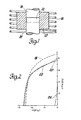
- the ribbon was broken into short pieces and they were placed into a cylindrical cavity 12 of a round die 10 like that depicted in Figure l.
- the cavity was 9.525 mn (3/8 inch) in diameter and the material was contained by upper and lower punches 14.
- the die was made of a high temperature nickel alloy with a tool steel liner, and the punches were tungsten carbide.
- the die and the contents were rapidly heated under argon with an induction coil 16 to a maximum temperature of 750°C.
- the temperature was measured using a thermocouple (not shown) in the die adjacent the cavity.
- the upper punch was then actuated to exert a maximum pressure of 220632.32 kPa (32,000 psi) on the broken-up ribbon particles. Heating and pressure were stopped.
- the workpiece was cooled to room temperature on the die. However, the total time that the workpiece was at a temperature above 700°C was only about five minutes.
- the consolidated workpiece was removed from the die.
- the resulting cylinder was hard and strong. It had a density of about 7.5 grams per cubic centimeter, which is substantially its full density.
- the magnetic properties of the material were determined by cutting a piece from the cylinder and grinding a small sphere, about 2 mm in diameter, from the cut off piece.
- the sphere was magnetized in a known direction by subjecting it to a pulsed magnetic field having a strength of about forty kilo gauss. -
- the sphere was then placed in a vibrating sample magnetometer with the positive magnetic pole of the sphere aligned with the positive pole of the magnetometer.
- the sample was subjected to a gradually decreasing magnetic field from +lOkOe to -20kOe that produced corresponding decreasing sample magnetization (4 ⁇ M). In this manner the second quadrant demagnetization plot (4 ⁇ M versus H) was obtained for the particular direction of magnetization.
- the sample was removed from the magnetometer and magnetized in a pulsed field as before in a different direction. It was returned to the magnetometer and a new demagnetization curve determined. This process was again repeated and the respective curves compared. The sample displayed magnetic anistropy.
- Figure 2 contains four different second quadrant plots of 4 ⁇ M versus H.
- the second quadrant portion of a hysteresis loop provides useful information regarding permanent magnet properties.
- Three of these plots in Figure 2 represent good properties.
- the upper curve 18 represents a favorable direction of magnetization obtained in the spherical sample.
- the lowest curve 20 represents the data obtained from a direction relatively far removed from the aligned direction of the hot pressed compact.
- the middle line 22 is the demagnetization plot also generated in the vibrating sample magnetometer of an isotropic array of the same ribbon from which its hot compact was made.
- plot 22 is of an isotropic magnet of the same composition as the anisotropic magnet produced in this example.
- a hysteresis curve was also prepared from a sample of the original overquenched ribbon.
- the second quadrant portion is produced as curve 24 in Figure 2. It has relatively low intrinsic coercivity and residual magnetization.
- the hot pressing operation produced a fully densified body and also produced flow in the material that oriented the microstructure so that it became magnetically anisotropic.
- the preferred direction of magnetization represented by curve 181 the residual magnetization and energy product are greater than in the isotropic material.
- hot pressed body In addition to having excellent permanent properties at room temperature the hot pressed body retains its properties during exposure at high temperatures in air.
- a hot pressed body of this example was exposed at 160°C in air to a reverse field of 4kOe for 1507 hours. It suffered only minimal loss in permanent magnet properties.
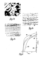
- Figure 3a is a photomicrograph of a cross-section of a bonded magnet that was compacted at room temperature to 85% of full density. The platelike sections of the original ribbon are seen to line up and be preserved in the bonded magnet.
- Figure 3b is a photomicrograph at the same magnification of a hot pressed specimen fully densified in accordance with the invention. The flat ribbon fragments are still perceptible at about the same size as in the bonded magnet, but there are no voids in this fully densified specimen.
- Example 2 Another overquenched, melt spun ribbon was prepared by the method described in Example 1.
- the nominal composition of the ribbon was in accordance with the empirical formula Nd 0.13 (Fe 0.94 B 0.06 ) 0.87 .
- the ribbons were produced by quenching the melt on a chill wheel rotating at a velocity of 32 m/s.
- the thickness of the ribbon was approximately 30 ⁇ m and the width approximately one millimeter. This cooling rate produced a microstructure that could not be magnetized to form a magnet having useful permanent magnet properties.
- Ribbon pieces were compacted at room temperature in a die to form a precompacted body of about 85% full density.
- the precompact was then placed in the cavity of a high temperature alloy die similar to that described in Example 1. However, the die had a graphite liner. Carbide punches confined the precompact in the die cavity.
- the die and its contents were quickly heated under argon to 740°C and a ram pressure of 68,947.6 k Pa (10 kpsi)was applied in an attempt to extrude the preform.
- An unexpected form of backward extrusion was obtained as the precompacted material flowed out from between the punches and displaced graphite die liner to form a cup-like piece. After cooling to room temperature this piece was removed from the die and it was found that the extruded portion of the sample was of sufficient dimensions to allow density measurement as well as magnetic measurement. The extruded portion was fully densified.
- a 2 mm cube was ground from a portion of the extruded metal and it was tested in a vibrating sample magnetometer. By magnetizing and demagnetizing the sample transverse to the cube faces it was observed that the specimen displayed magnetic anisatmpy. Three orthogonal directions are displayed in Figure 4- by curves 26, 28 and 30. The separations of these second quadrant plots from different directions of magnetization results from physical alignment of magnetic domains within the sample. The greater the separation of the plots, the greater the degree of magnetic alignment. It is seen that the alignment.for the extruded sample was even more pronounced than for the sample of Figure 1.
- the demagnetization curves for the annealed ribbon 22 and the overquenched ribbon 24 are also included in this figure as in Figure 2.
- the coercivity of the extruded sample is even higher than that of the annealed ribbons pre-. sumably because a more appropriate crystallite size was achieved during the extrusion.
- the magnetization of the extruded sample in its most preferred direction is higher and results in higher energy product than that obtainable in isotropic annealed ribbons.
- Figure 3c is a photomicrograph at 600X magnification of a cross-section of the extruded sample. It is seen that greater plastic flow occurred in the extruded sample as evidenced by the reduction in thickness of the original ribbon particles. It is believed that this plastic flow is essential to alignment of the magnetic moments within the material and that this alignment is generally transverse to the plastic flow. In other words, with respect to this sample, the magnetic alignment is transverse to the long dimension of the extruded ribbons (i.e., up and down in Figure 3c).
- Figure 5 is a scanning electron microscope micrograph at nearly 44,000X magnification of a fracture surface of the extruded sample. It shows the fine grain texture.
- Example 1 Additional hot press tests, like Example 1, and modified extrusion tests, like Example 2, were carried out at various die temperatures in the range of 700 to 770°C and pressures in the range of 68,947.6 to 206,842.8 kPa (10,000 to 30,000 psi). These tests shewed that full densification could be realized even at the lower pressures and temperatures. However, the samples prepared at the lower temperatures and pressures appeared to be more brittle. Optical micrographs revealed the ribbon pieces to have cracks similar to those present in Figure 3a. Evidently, higher pressure is required at temperatures of 750°C and lower before such cracks disappear as in Figure 3b.
- the preferred magnetization direction for the hot pressed samples is parallel to the press direction and perpendicular to the direction of plastic flow. Greater directional anisotropy develops when more plastic flow is allowed, as in the extrusion tests.
- This example illustrates a die upsetting practice.
- This cylinder was re-hot pressed in the original diameter cavity along its axis (perpendicular to the original press direction) so that it was free to deform to a shorter cylinder of 9.525 nm (3/8" ) diameter (i.e., die upsetting).
- the die upsetting operation was conducted at a naximum temperature of 770°C and a pressure of 110, 316.16 kPa (16 kpsi).
- the part was cooled in the die.
- a cubic specimen was machined from the die upset body and its magnetic properties measured parallel and transverse to the press direction in a vibrating sample magnetometer, as in the above Examples 1 and 2. Second quadrant, room temperature 4 ⁇ M versus H plots for these two directions are depicted in Figure 6.
- Example 3 illustrates a die upsetting practice similar to Example 3, except a fully dense, hot pressed sample was die-upset with pressure applied in the same direction as the original hot press pressure.
- Overquenched ribbon fragments of Example 2 were hot pressed under argon in a heated die, like that depicted in Figure 1, at a maximum temperature of 760°C and pressure of 103,421.4 kpa (15 kpsi).
- This hot pressed piece was sanded to a smaller diameter (less than about 1 cm) and die upset in the same diameter cavity in a direction parallel to the first press direction.
- the die upset operation was conducted at a maximum temperature of 750°C and a pressure of 82,737.1 kPa (12 kpsi). The sample was cooled in the die.
- This practice of high'temperature consolidation and plastic flow can be viewed as a strain-anneal process.
- This process produces magnetic alignment of the grains of the workpiece and grain growth.
- the grain growth is excessive, coercivity is decreased. Therefore, consideration (and probably trial and error testing) must be given to the grain size of the starting material in conjunction with the time that the material is at a temperature at which grain growth can occur. If, as is preferred, the starting material is overquenched, the workpiece can be held at a relatively high temperature for a longer time because some grain growth is desired. If one starts with near optimal grain size material, the hot working must be rapid and subsequent cooling prompt to retard excessive grain growth.
- Hot pressing experiments were also conducted on annealed ingot that had a homogenized, large grain microstructure. When magnetized, such ingots contained very low coercivity, less than 500 oersted.
- the present hot pressing strain-anneal practice produced a significant directional dependence of B in the ingot samples, but no coercivity increase. It had been hoped that the strain-anneal practice would induce recrystallization in the ingot which would allow for development of the optimal grain size. The failure to obtain a coercivity increase in these experiments indicates that the strain-anneal practice is not beneficially applicable to large grained materials.
- this high temperature-high pressure consolidation and hot working of suitable, transition metal, rare earth metal, boron compositions yields magnetically anisotropic product of excellent permanent magnet properties.
- the practice of the present invention has been described, using specific composition]of neodymium, ircn and boron.
- other materials may be substituted or present in suitably small amounts.
- Praseodymium may be substituted for neodymium or used in combination with it.
- Other rare earth metals may be used with neodymium and/or praseodymium.
- other metals, such as cobalt, nickel, manganese and chromium, in suitably small amounts may be used in combination with iron.
- the preferred compositional ranges are described above.
Landscapes
- Chemical & Material Sciences (AREA)
- Crystallography & Structural Chemistry (AREA)
- Inorganic Chemistry (AREA)
- Engineering & Computer Science (AREA)
- Power Engineering (AREA)
- Hard Magnetic Materials (AREA)
- Manufacturing Of Steel Electrode Plates (AREA)
- Manufacturing Cores, Coils, And Magnets (AREA)
Applications Claiming Priority (2)
| Application Number | Priority Date | Filing Date | Title |
|---|---|---|---|
| US52017083A | 1983-08-04 | 1983-08-04 | |
| US520170 | 1983-08-04 |
Publications (3)
| Publication Number | Publication Date |
|---|---|
| EP0133758A2 true EP0133758A2 (fr) | 1985-03-06 |
| EP0133758A3 EP0133758A3 (en) | 1987-05-20 |
| EP0133758B1 EP0133758B1 (fr) | 1990-09-19 |
Family
ID=24071457
Family Applications (1)
| Application Number | Title | Priority Date | Filing Date |
|---|---|---|---|
| EP84304731A Expired - Lifetime EP0133758B1 (fr) | 1983-08-04 | 1984-07-11 | Aimants permanents à partir de fer, de métaux de terres rares et de bore, par traitement thermique |
Country Status (8)
| Country | Link |
|---|---|
| EP (1) | EP0133758B1 (fr) |
| JP (1) | JPS60100402A (fr) |
| AU (1) | AU574697B2 (fr) |
| BR (1) | BR8403875A (fr) |
| CA (1) | CA1236381A (fr) |
| DE (1) | DE3483226D1 (fr) |
| ES (1) | ES8507289A1 (fr) |
| MX (1) | MX167658B (fr) |
Cited By (42)
| Publication number | Priority date | Publication date | Assignee | Title |
|---|---|---|---|---|
| DE3514516A1 (de) * | 1984-04-24 | 1985-10-24 | Nippon Gakki Seizo K.K., Hamamatsu, Shizuoka | Seltenerdmagnet und verfahren zu dessen herstellung |
| FR2586323A1 (fr) * | 1985-08-13 | 1987-02-20 | Seiko Epson Corp | Aimant permanent a base de terres rares-fer |
| EP0231620A2 (fr) * | 1986-01-29 | 1987-08-12 | General Motors Corporation | Fabrication d'un aimant permanent à partir d'un alliage cristallin à coercitivité très faible de terre rare-métal de transition-bore |
| EP0239031A1 (fr) * | 1986-03-20 | 1987-09-30 | Hitachi Metals, Ltd. | Procede de preparation d'une poudre magnetique pour un aimant lie a alimentation anisotropique |
| FR2598949A1 (fr) * | 1986-05-23 | 1987-11-27 | Centre Nat Rech Scient | Procede pour la preparation de cristaux finement divises a partir d'un alliage metallique, notamment pour la preparation d'aimants permanents |
| NL8701452A (nl) * | 1986-06-20 | 1988-01-18 | Seiko Epson Corp | Permanente magneten in de zeldzaam aardmetaal-ijzerreeks. |
| EP0253521A2 (fr) * | 1986-07-15 | 1988-01-20 | General Motors Corporation | Méthode de broyage à billes à grande énergie pour la fabrication d'aimants permanents terre rare-métal de transition-bore |
| EP0261292A2 (fr) * | 1986-07-28 | 1988-03-30 | Crucible Materials Corporation | Procédé de fabrication d'aimant permanent en alliage de haute densité |
| EP0274034A2 (fr) * | 1987-01-06 | 1988-07-13 | Hitachi Metals, Ltd. | Poudre magnétique anisotrope, aimant à partir de celui-ci, et méthode de fabrication |
| EP0288637A2 (fr) * | 1987-04-30 | 1988-11-02 | Seiko Epson Corporation | Aimant permanent et son procédé de fabrication |
| EP0306981A1 (fr) * | 1987-09-11 | 1989-03-15 | Hitachi Metals, Ltd. | Aimant permanent pour l'accélération de rayons corpusculaires |
| EP0306928A2 (fr) * | 1987-09-09 | 1989-03-15 | Hitachi Metals, Ltd. | Aimant pour un moteur et son procédé de fabrication |
| EP0306599A2 (fr) * | 1987-09-10 | 1989-03-15 | Hitachi Metals, Ltd. | Méthode et appareil de production de matériau pour aimant, magnétiquement anisotropique à base de Nd-Fe-B |
| DE3839545A1 (de) * | 1987-11-27 | 1989-06-08 | Hitachi Metals Ltd | Verfahren und vorrichtung zur herstellung eines magnetisch anisotropen materiales |
| US4842656A (en) * | 1987-06-12 | 1989-06-27 | General Motors Corporation | Anisotropic neodymium-iron-boron powder with high coercivity |
| EP0331286A2 (fr) * | 1988-03-03 | 1989-09-06 | General Motors Corporation | Compactage rapide d'alliages terres rares-métaux de transistion dans une matrice remplie d'un fluide |
| US4867809A (en) * | 1988-04-28 | 1989-09-19 | General Motors Corporation | Method for making flakes of RE-Fe-B type magnetically aligned material |
| EP0334478A2 (fr) * | 1988-03-24 | 1989-09-27 | General Motors Corporation | Fabrication de fractions à large volume du type RE-Fe-B, matériau magnétiquement aligné, par écrasement |
| US4881985A (en) * | 1988-08-05 | 1989-11-21 | General Motors Corporation | Method for producing anisotropic RE-FE-B type magnetically aligned material |
| US4892596A (en) * | 1988-02-23 | 1990-01-09 | Eastman Kodak Company | Method of making fully dense anisotropic high energy magnets |
| US4895607A (en) * | 1988-07-25 | 1990-01-23 | Kubota, Ltd. | Iron-neodymium-boron permanent magnet alloys prepared by consolidation of amorphous powders |
| US4919732A (en) * | 1988-07-25 | 1990-04-24 | Kubota Ltd. | Iron-neodymium-boron permanent magnet alloys which contain dispersed phases and have been prepared using a rapid solidification process |
| US4920009A (en) * | 1988-08-05 | 1990-04-24 | General Motors Corporation | Method for producing laminated bodies comprising an RE-FE-B type magnetic layer and a metal backing layer |
| EP0378698A1 (fr) * | 1988-06-21 | 1990-07-25 | Matsushita Electric Industrial Co., Ltd. | Procede et production d'aimants permanents |
| US4952251A (en) * | 1989-05-23 | 1990-08-28 | Hitachi Metals, Ltd. | Magnetically anisotropic hotworked magnet and method of producing same |
| US4978398A (en) * | 1988-09-30 | 1990-12-18 | Hitachi Metals, Ltd. | Magnetically anisotropic hot-worked magnet and method of producing same |
| US4985085A (en) * | 1988-02-23 | 1991-01-15 | Eastman Kodak Company | Method of making anisotropic magnets |
| US5000796A (en) * | 1988-02-23 | 1991-03-19 | Eastman Kodak Company | Anisotropic high energy magnets and a process of preparing the same |
| US5026419A (en) * | 1989-05-23 | 1991-06-25 | Hitachi Metals, Ltd. | Magnetically anisotropic hotworked magnet and method of producing same |
| US5098486A (en) * | 1989-05-23 | 1992-03-24 | Hitachi Metals, Ltd. | Magnetically anisotropic hotworked magnet and method of producing same |
| US5100741A (en) * | 1984-09-12 | 1992-03-31 | Seiko Epson Corporation | Magneto-optic recording systems |
| US5162063A (en) * | 1989-11-14 | 1992-11-10 | Hitachi Metals Ltd. | Magnetically anisotropic r-t-b magnet |
| US5186761A (en) * | 1987-04-30 | 1993-02-16 | Seiko Epson Corporation | Magnetic alloy and method of production |
| US5460662A (en) * | 1987-04-30 | 1995-10-24 | Seiko Epson Corporation | Permanent magnet and method of production |
| US5529854A (en) * | 1984-09-12 | 1996-06-25 | Seiko Epson Corporation | Magneto-optic recording systems |
| US5536334A (en) * | 1988-06-02 | 1996-07-16 | Seiko Epson Corporation | Permanent magnet and a manufacturing method thereof |
| US5538565A (en) * | 1985-08-13 | 1996-07-23 | Seiko Epson Corporation | Rare earth cast alloy permanent magnets and methods of preparation |
| US6136099A (en) * | 1985-08-13 | 2000-10-24 | Seiko Epson Corporation | Rare earth-iron series permanent magnets and method of preparation |
| USRE38042E1 (en) * | 1987-01-06 | 2003-03-25 | Hitachi Metals, Ltd. | Anisotropic magnetic powder and magnet thereof and method of producing same |
| WO2012114192A1 (fr) * | 2011-02-23 | 2012-08-30 | Toyota Jidosha Kabushiki Kaisha | Procédé permettant de produire un aimant aux terres rares |
| CN105312575A (zh) * | 2014-07-25 | 2016-02-10 | 丰田自动车株式会社 | 制备稀土磁石的方法 |
| US10460871B2 (en) | 2015-10-30 | 2019-10-29 | GM Global Technology Operations LLC | Method for fabricating non-planar magnet |
Families Citing this family (32)
| Publication number | Priority date | Publication date | Assignee | Title |
|---|---|---|---|---|
| CA1216623A (fr) * | 1983-05-09 | 1987-01-13 | John J. Croat | Aimants de terre rare frittee |
| JPS62276803A (ja) * | 1985-08-13 | 1987-12-01 | Seiko Epson Corp | 希土類−鉄系永久磁石 |
| EP0229946B1 (fr) * | 1986-01-10 | 1991-10-16 | Ovonic Synthetic Materials Company, Inc. | Alliage magnétique permanent |
| JP2546988B2 (ja) * | 1986-04-30 | 1996-10-23 | 株式会社 トーキン | 耐酸化性に優れた永久磁石 |
| JP2546989B2 (ja) * | 1986-04-30 | 1996-10-23 | 株式会社 トーキン | 耐酸化性に優れた永久磁石 |
| JP2546990B2 (ja) * | 1986-04-30 | 1996-10-23 | 株式会社 トーキン | 耐酸化性に優れた永久磁石 |
| JP2611221B2 (ja) * | 1986-05-01 | 1997-05-21 | セイコーエプソン株式会社 | 永久磁石の製造方法 |
| JP2731150B2 (ja) * | 1986-10-14 | 1998-03-25 | 日立金属株式会社 | 磁気異方性ボンド磁石、それに用いる磁気異方性磁粉およびその製造方法、ならびに磁気異方性圧粉磁石 |
| JPS63152110A (ja) * | 1986-12-17 | 1988-06-24 | Daido Steel Co Ltd | 永久磁石の製造方法 |
| JPH01115105A (ja) * | 1987-10-28 | 1989-05-08 | Matsushita Electric Ind Co Ltd | 希土類磁石の製造法 |
| JPH01115106A (ja) * | 1987-10-28 | 1989-05-08 | Matsushita Electric Ind Co Ltd | 希土類磁石の製造法 |
| JPH01115104A (ja) * | 1987-10-28 | 1989-05-08 | Matsushita Electric Ind Co Ltd | 希土類磁石の製造法 |
| JP2558760B2 (ja) * | 1987-12-08 | 1996-11-27 | 松下電器産業株式会社 | 異方性永久磁石 |
| JPH01208813A (ja) * | 1988-02-17 | 1989-08-22 | Matsushita Electric Ind Co Ltd | 希土類磁石の製造方法 |
| JPH01297807A (ja) * | 1988-05-26 | 1989-11-30 | Daido Steel Co Ltd | 永久磁石の製造方法 |
| JP3061808B2 (ja) * | 1988-09-22 | 2000-07-10 | 松下電器産業株式会社 | Fe−B−R系永久磁石の製造方法 |
| JP2623731B2 (ja) * | 1988-07-29 | 1997-06-25 | 三菱マテリアル株式会社 | 希土類―Fe―B系異方性永久磁石の製造法 |
| JPH0257662A (ja) * | 1988-08-23 | 1990-02-27 | M G:Kk | ボンド磁石用急冷薄帯合金 |
| DE68916184T2 (de) * | 1988-11-14 | 1994-11-17 | Asahi Chemical Ind | Magnetische Stoffe, enthaltend Seltenerdelemente, Eisen, Stickstoff und Wasserstoff. |
| JPH02133519A (ja) * | 1988-11-15 | 1990-05-22 | Seiko Electronic Components Ltd | 希土類,ボロン,鉄系磁石の製造方法 |
| JPH02247304A (ja) * | 1989-03-17 | 1990-10-03 | Nippon Steel Corp | Nd合金注湯用ノズル |
| JPH0344904A (ja) * | 1989-07-12 | 1991-02-26 | Matsushita Electric Ind Co Ltd | 希土類・鉄系永久磁石の製造方法 |
| JP2596835B2 (ja) * | 1989-08-04 | 1997-04-02 | 新日本製鐵株式会社 | 希土類系異方性粉末および希土類系異方性磁石 |
| US5201963A (en) * | 1989-10-26 | 1993-04-13 | Nippon Steel Corporation | Rare earth magnets and method of producing same |
| JP2780429B2 (ja) * | 1990-03-30 | 1998-07-30 | 松下電器産業株式会社 | 希土類―鉄系磁石の製造方法 |
| US5178691A (en) * | 1990-05-29 | 1993-01-12 | Matsushita Electric Industrial Co., Ltd. | Process for producing a rare earth element-iron anisotropic magnet |
| JP2010222601A (ja) | 2009-03-19 | 2010-10-07 | Honda Motor Co Ltd | 希土類永久磁石およびその製造方法 |
| JP2012023190A (ja) * | 2010-07-14 | 2012-02-02 | Toyota Motor Corp | 異方性希土類磁石の製造方法 |
| JP6447395B2 (ja) * | 2015-07-09 | 2019-01-09 | トヨタ自動車株式会社 | 鍛造加工方法 |
| CN108242305B (zh) * | 2016-12-27 | 2020-03-27 | 有研稀土新材料股份有限公司 | 稀土永磁材料及其制备方法 |
| CN108428541B (zh) * | 2017-02-14 | 2020-05-22 | 中国科学院宁波材料技术与工程研究所 | 一种超细晶高性能各向异性钕铁硼永磁体的制备方法 |
| JP7021035B2 (ja) | 2018-09-18 | 2022-02-16 | 株式会社東芝 | 永久磁石、回転電機、及び車 |
Citations (5)
| Publication number | Priority date | Publication date | Assignee | Title |
|---|---|---|---|---|
| CH525547A (de) * | 1970-12-21 | 1972-07-15 | Bbc Brown Boveri & Cie | Verfahren zur Herstellung von Feinpartikel-Dauermagneten |
| JPS57141901A (en) * | 1981-02-26 | 1982-09-02 | Mitsubishi Steel Mfg Co Ltd | Permanent magnet powder |
| US4358419A (en) * | 1980-11-12 | 1982-11-09 | The United States Of America As Represented By The United States Department Of Energy | Method of making amorphous metal composites |
| EP0101552A2 (fr) * | 1982-08-21 | 1984-02-29 | Sumitomo Special Metals Co., Ltd. | Matériaux magnétiques, aimants permanents et procédés pour leur production |
| EP0108474A2 (fr) * | 1982-09-03 | 1984-05-16 | General Motors Corporation | Alliages de RE-TM-B, procédé de production et aimants permanents contenant tels alliages |
Family Cites Families (4)
| Publication number | Priority date | Publication date | Assignee | Title |
|---|---|---|---|---|
| JPS58123853A (ja) * | 1982-01-18 | 1983-07-23 | Fujitsu Ltd | 希土類−鉄系永久磁石およびその製造方法 |
| JPS59177346A (ja) * | 1983-03-25 | 1984-10-08 | Sumitomo Special Metals Co Ltd | 希土類磁石素材用配合合金 |
| CA1216623A (fr) * | 1983-05-09 | 1987-01-13 | John J. Croat | Aimants de terre rare frittee |
| AU572120B2 (en) * | 1983-06-24 | 1988-05-05 | General Motors Corporation | High energy product rare earth transition metal magnet alloys |
-
1984
- 1984-04-12 CA CA000451851A patent/CA1236381A/fr not_active Expired
- 1984-07-11 EP EP84304731A patent/EP0133758B1/fr not_active Expired - Lifetime
- 1984-07-11 DE DE8484304731T patent/DE3483226D1/de not_active Expired - Lifetime
- 1984-07-23 AU AU30962/84A patent/AU574697B2/en not_active Ceased
- 1984-08-03 MX MX2660784A patent/MX167658B/es unknown
- 1984-08-03 BR BR8403875A patent/BR8403875A/pt not_active IP Right Cessation
- 1984-08-03 ES ES534879A patent/ES8507289A1/es not_active Expired
- 1984-08-04 JP JP59163486A patent/JPS60100402A/ja active Granted
Patent Citations (5)
| Publication number | Priority date | Publication date | Assignee | Title |
|---|---|---|---|---|
| CH525547A (de) * | 1970-12-21 | 1972-07-15 | Bbc Brown Boveri & Cie | Verfahren zur Herstellung von Feinpartikel-Dauermagneten |
| US4358419A (en) * | 1980-11-12 | 1982-11-09 | The United States Of America As Represented By The United States Department Of Energy | Method of making amorphous metal composites |
| JPS57141901A (en) * | 1981-02-26 | 1982-09-02 | Mitsubishi Steel Mfg Co Ltd | Permanent magnet powder |
| EP0101552A2 (fr) * | 1982-08-21 | 1984-02-29 | Sumitomo Special Metals Co., Ltd. | Matériaux magnétiques, aimants permanents et procédés pour leur production |
| EP0108474A2 (fr) * | 1982-09-03 | 1984-05-16 | General Motors Corporation | Alliages de RE-TM-B, procédé de production et aimants permanents contenant tels alliages |
Cited By (78)
| Publication number | Priority date | Publication date | Assignee | Title |
|---|---|---|---|---|
| DE3514516A1 (de) * | 1984-04-24 | 1985-10-24 | Nippon Gakki Seizo K.K., Hamamatsu, Shizuoka | Seltenerdmagnet und verfahren zu dessen herstellung |
| US5529854A (en) * | 1984-09-12 | 1996-06-25 | Seiko Epson Corporation | Magneto-optic recording systems |
| US5100741A (en) * | 1984-09-12 | 1992-03-31 | Seiko Epson Corporation | Magneto-optic recording systems |
| US5597425A (en) * | 1985-08-13 | 1997-01-28 | Seiko Epson Corporation | Rare earth cast alloy permanent magnets and methods of preparation |
| DE3626406A1 (de) * | 1985-08-13 | 1987-02-26 | Seiko Epson Corp | Verfahren zur herstellung von dauermagneten auf der basis von seltenerdmetallen |
| US5560784A (en) * | 1985-08-13 | 1996-10-01 | Seiko Epson Corporation | Rare earth cast alloy permanent magnets and methods of preparation |
| US6136099A (en) * | 1985-08-13 | 2000-10-24 | Seiko Epson Corporation | Rare earth-iron series permanent magnets and method of preparation |
| US5538565A (en) * | 1985-08-13 | 1996-07-23 | Seiko Epson Corporation | Rare earth cast alloy permanent magnets and methods of preparation |
| FR2586323A1 (fr) * | 1985-08-13 | 1987-02-20 | Seiko Epson Corp | Aimant permanent a base de terres rares-fer |
| US5565043A (en) * | 1985-08-13 | 1996-10-15 | Seiko Epson Corporation | Rare earth cast alloy permanent magnets and methods of preparation |
| EP0231620A3 (en) * | 1986-01-29 | 1988-01-27 | General Motors Corporation | Permanent magnet manufacture from very low coercivity crystalline rare earth-transition metal-boron alloy |
| EP0231620A2 (fr) * | 1986-01-29 | 1987-08-12 | General Motors Corporation | Fabrication d'un aimant permanent à partir d'un alliage cristallin à coercitivité très faible de terre rare-métal de transition-bore |
| US4921551A (en) * | 1986-01-29 | 1990-05-01 | General Motors Corporation | Permanent magnet manufacture from very low coercivity crystalline rare earth-transition metal-boron alloy |
| US4952239A (en) * | 1986-03-20 | 1990-08-28 | Hitachi Metals, Ltd. | Magnetically anisotropic bond magnet, magnetic powder for the magnet and manufacturing method of the powder |
| US4921553A (en) * | 1986-03-20 | 1990-05-01 | Hitachi Metals, Ltd. | Magnetically anisotropic bond magnet, magnetic powder for the magnet and manufacturing method of the powder |
| US5085715A (en) * | 1986-03-20 | 1992-02-04 | Hitachi Metals, Ltd. | Magnetically anisotropic bond magnet, magnetic powder for the magnet and manufacturing method of the powder |
| EP0239031A1 (fr) * | 1986-03-20 | 1987-09-30 | Hitachi Metals, Ltd. | Procede de preparation d'une poudre magnetique pour un aimant lie a alimentation anisotropique |
| US5055142A (en) * | 1986-05-23 | 1991-10-08 | Centre National De La Recherche Scientifique | Process for preparing permanent magnets by division of crystals |
| WO1987007425A1 (fr) * | 1986-05-23 | 1987-12-03 | Centre National De La Recherche Scientifique (Cnrs | Procede pour la preparation d'aimants permanents par division de cristaux |
| FR2598949A1 (fr) * | 1986-05-23 | 1987-11-27 | Centre Nat Rech Scient | Procede pour la preparation de cristaux finement divises a partir d'un alliage metallique, notamment pour la preparation d'aimants permanents |
| NL8701452A (nl) * | 1986-06-20 | 1988-01-18 | Seiko Epson Corp | Permanente magneten in de zeldzaam aardmetaal-ijzerreeks. |
| EP0253521A2 (fr) * | 1986-07-15 | 1988-01-20 | General Motors Corporation | Méthode de broyage à billes à grande énergie pour la fabrication d'aimants permanents terre rare-métal de transition-bore |
| EP0253521A3 (fr) * | 1986-07-15 | 1990-02-07 | General Motors Corporation | Méthode de broyage à billes à grande énergie pour la fabrication d'aimants permanents terre rare-métal de transition-bore |
| EP0261292A2 (fr) * | 1986-07-28 | 1988-03-30 | Crucible Materials Corporation | Procédé de fabrication d'aimant permanent en alliage de haute densité |
| US4881984A (en) * | 1986-07-28 | 1989-11-21 | Crucible Materials Corporation | Consolidation of magnet alloy powders by extrusion and product therefrom |
| EP0261292A3 (en) * | 1986-07-28 | 1988-07-27 | Crucible Materials Corporation | Method of producing fully dense permanent magnet alloy article and article produced thereby |
| EP0274034A3 (en) * | 1987-01-06 | 1989-03-08 | Hitachi Metals, Ltd. | Anisotropic magnetic powder, magnet thereof and method of producing same |
| USRE38021E1 (en) | 1987-01-06 | 2003-03-11 | Hitachi Metals, Ltd. | Anisotropic magnetic powder and magnet thereof and method of producing same |
| USRE38042E1 (en) * | 1987-01-06 | 2003-03-25 | Hitachi Metals, Ltd. | Anisotropic magnetic powder and magnet thereof and method of producing same |
| EP0274034A2 (fr) * | 1987-01-06 | 1988-07-13 | Hitachi Metals, Ltd. | Poudre magnétique anisotrope, aimant à partir de celui-ci, et méthode de fabrication |
| US4983232A (en) * | 1987-01-06 | 1991-01-08 | Hitachi Metals, Ltd. | Anisotropic magnetic powder and magnet thereof and method of producing same |
| US5186761A (en) * | 1987-04-30 | 1993-02-16 | Seiko Epson Corporation | Magnetic alloy and method of production |
| US5460662A (en) * | 1987-04-30 | 1995-10-24 | Seiko Epson Corporation | Permanent magnet and method of production |
| EP0288637A2 (fr) * | 1987-04-30 | 1988-11-02 | Seiko Epson Corporation | Aimant permanent et son procédé de fabrication |
| US5076861A (en) * | 1987-04-30 | 1991-12-31 | Seiko Epson Corporation | Permanent magnet and method of production |
| EP0288637A3 (en) * | 1987-04-30 | 1989-08-30 | Seiko Epson Corporation | Permanent magnet and method of making the same |
| US4842656A (en) * | 1987-06-12 | 1989-06-27 | General Motors Corporation | Anisotropic neodymium-iron-boron powder with high coercivity |
| EP0306928B1 (fr) * | 1987-09-09 | 1993-12-01 | Hitachi Metals, Ltd. | Aimant pour un moteur et son procédé de fabrication |
| EP0306928A2 (fr) * | 1987-09-09 | 1989-03-15 | Hitachi Metals, Ltd. | Aimant pour un moteur et son procédé de fabrication |
| US4985086A (en) * | 1987-09-10 | 1991-01-15 | Hitachi Metals, Ltd. | Method and apparatus for producing magnetically anisotropic Nd-Fe-B magnet material |
| EP0306599A2 (fr) * | 1987-09-10 | 1989-03-15 | Hitachi Metals, Ltd. | Méthode et appareil de production de matériau pour aimant, magnétiquement anisotropique à base de Nd-Fe-B |
| EP0306599A3 (en) * | 1987-09-10 | 1990-07-25 | Hitachi Metals, Ltd. | Method and apparatus for producing magnetically anisotropic nd-fe-b magnet material |
| EP0306981A1 (fr) * | 1987-09-11 | 1989-03-15 | Hitachi Metals, Ltd. | Aimant permanent pour l'accélération de rayons corpusculaires |
| US5292380A (en) * | 1987-09-11 | 1994-03-08 | Hitachi Metals, Ltd. | Permanent magnet for accelerating corpuscular beam |
| DE3839545A1 (de) * | 1987-11-27 | 1989-06-08 | Hitachi Metals Ltd | Verfahren und vorrichtung zur herstellung eines magnetisch anisotropen materiales |
| US4960469A (en) * | 1987-11-27 | 1990-10-02 | Hitachi Metals, Ltd. | Method of manufacturing magnetically anisotropic magnet materials and device for same |
| US5039292A (en) * | 1987-11-27 | 1991-08-13 | Hitachi Metals, Ltd. | Device for manufacturing magnetically anisotropic magnets |
| US4892596A (en) * | 1988-02-23 | 1990-01-09 | Eastman Kodak Company | Method of making fully dense anisotropic high energy magnets |
| US4985085A (en) * | 1988-02-23 | 1991-01-15 | Eastman Kodak Company | Method of making anisotropic magnets |
| US5000796A (en) * | 1988-02-23 | 1991-03-19 | Eastman Kodak Company | Anisotropic high energy magnets and a process of preparing the same |
| EP0331286A2 (fr) * | 1988-03-03 | 1989-09-06 | General Motors Corporation | Compactage rapide d'alliages terres rares-métaux de transistion dans une matrice remplie d'un fluide |
| EP0331286A3 (fr) * | 1988-03-03 | 1989-11-02 | General Motors Corporation | Compactage rapide d'alliages terres rares-métaux de transistion dans une matrice remplie d'un fluide |
| EP0334478A3 (en) * | 1988-03-24 | 1990-12-19 | General Motors Corporation | Die-upset manufacture to produce high volume fractions of re-fe-b type magnetically-aligned material |
| EP0334478A2 (fr) * | 1988-03-24 | 1989-09-27 | General Motors Corporation | Fabrication de fractions à large volume du type RE-Fe-B, matériau magnétiquement aligné, par écrasement |
| EP0339767B1 (fr) * | 1988-04-28 | 1994-04-27 | General Motors Corporation | Méthode et appareil de fabrication de copeaux en matériau du type RE-Fe-B magnétiquement aligné |
| EP0339767A2 (fr) * | 1988-04-28 | 1989-11-02 | General Motors Corporation | Méthode et appareil de fabrication de copeaux en matériau du type RE-Fe-B magnétiquement aligné |
| US4867809A (en) * | 1988-04-28 | 1989-09-19 | General Motors Corporation | Method for making flakes of RE-Fe-B type magnetically aligned material |
| US5536334A (en) * | 1988-06-02 | 1996-07-16 | Seiko Epson Corporation | Permanent magnet and a manufacturing method thereof |
| EP0378698A4 (en) * | 1988-06-21 | 1991-07-31 | Matsushita Electric Industrial Co., Ltd. | Method of producing permanent magnet |
| US5100485A (en) * | 1988-06-21 | 1992-03-31 | Matsushita Electric Industrial Co., Ltd. | Method for manufacturing permanent magnets |
| EP0378698A1 (fr) * | 1988-06-21 | 1990-07-25 | Matsushita Electric Industrial Co., Ltd. | Procede et production d'aimants permanents |
| US4919732A (en) * | 1988-07-25 | 1990-04-24 | Kubota Ltd. | Iron-neodymium-boron permanent magnet alloys which contain dispersed phases and have been prepared using a rapid solidification process |
| US4895607A (en) * | 1988-07-25 | 1990-01-23 | Kubota, Ltd. | Iron-neodymium-boron permanent magnet alloys prepared by consolidation of amorphous powders |
| US4881985A (en) * | 1988-08-05 | 1989-11-21 | General Motors Corporation | Method for producing anisotropic RE-FE-B type magnetically aligned material |
| US4920009A (en) * | 1988-08-05 | 1990-04-24 | General Motors Corporation | Method for producing laminated bodies comprising an RE-FE-B type magnetic layer and a metal backing layer |
| US4978398A (en) * | 1988-09-30 | 1990-12-18 | Hitachi Metals, Ltd. | Magnetically anisotropic hot-worked magnet and method of producing same |
| US5125990A (en) * | 1988-09-30 | 1992-06-30 | Hitachi Metals | Magnetically anisotropic hot-worked magnet and method of producing same |
| US4952251A (en) * | 1989-05-23 | 1990-08-28 | Hitachi Metals, Ltd. | Magnetically anisotropic hotworked magnet and method of producing same |
| US5098486A (en) * | 1989-05-23 | 1992-03-24 | Hitachi Metals, Ltd. | Magnetically anisotropic hotworked magnet and method of producing same |
| US5026419A (en) * | 1989-05-23 | 1991-06-25 | Hitachi Metals, Ltd. | Magnetically anisotropic hotworked magnet and method of producing same |
| US5286308A (en) * | 1989-11-14 | 1994-02-15 | Hitachi Metals Ltd. | Magnetically anisotropic R-T-B magnet |
| US5162063A (en) * | 1989-11-14 | 1992-11-10 | Hitachi Metals Ltd. | Magnetically anisotropic r-t-b magnet |
| WO2012114192A1 (fr) * | 2011-02-23 | 2012-08-30 | Toyota Jidosha Kabushiki Kaisha | Procédé permettant de produire un aimant aux terres rares |
| CN103403815A (zh) * | 2011-02-23 | 2013-11-20 | 丰田自动车株式会社 | 制造稀土磁体的方法 |
| US9111679B2 (en) | 2011-02-23 | 2015-08-18 | Toyota Jidosha Kabushiki Kaisha | Method producing rare earth magnet |
| CN103403815B (zh) * | 2011-02-23 | 2016-10-12 | 丰田自动车株式会社 | 制造稀土磁体的方法 |
| CN105312575A (zh) * | 2014-07-25 | 2016-02-10 | 丰田自动车株式会社 | 制备稀土磁石的方法 |
| US10460871B2 (en) | 2015-10-30 | 2019-10-29 | GM Global Technology Operations LLC | Method for fabricating non-planar magnet |
Also Published As
| Publication number | Publication date |
|---|---|
| AU574697B2 (en) | 1988-07-14 |
| ES534879A0 (es) | 1985-08-16 |
| MX167658B (es) | 1993-04-01 |
| CA1236381A (fr) | 1988-05-10 |
| DE3483226D1 (de) | 1990-10-25 |
| JPS60100402A (ja) | 1985-06-04 |
| EP0133758A3 (en) | 1987-05-20 |
| ES8507289A1 (es) | 1985-08-16 |
| AU3096284A (en) | 1985-02-07 |
| EP0133758B1 (fr) | 1990-09-19 |
| BR8403875A (pt) | 1985-07-09 |
| JPH0420242B2 (fr) | 1992-04-02 |
Similar Documents
| Publication | Publication Date | Title |
|---|---|---|
| EP0133758B1 (fr) | Aimants permanents à partir de fer, de métaux de terres rares et de bore, par traitement thermique | |
| US4792367A (en) | Iron-rare earth-boron permanent | |
| US4844754A (en) | Iron-rare earth-boron permanent magnets by hot working | |
| US5110374A (en) | Rare earth-iron-boron magnet powder and process of producing same | |
| US4585473A (en) | Method for making rare-earth element containing permanent magnets | |
| EP0239031B2 (fr) | Procede de preparation d'une poudre magnetique pour un aimant lie a alimentation anisotropique | |
| CA1269029A (fr) | Fabrication d'un aimant permanent en alliage de metal de transition de terre rare et de bore | |
| US5352301A (en) | Hot pressed magnets formed from anisotropic powders | |
| EP0284033B1 (fr) | Méthode pour la fabrication d'un aimant anisotrope à liant, à base de terre rare-fer-bore, à partir de copeaux rubanés en alliage terre rare-fer-bore rapidement trempé | |
| US5565043A (en) | Rare earth cast alloy permanent magnets and methods of preparation | |
| US4842656A (en) | Anisotropic neodymium-iron-boron powder with high coercivity | |
| US4710239A (en) | Hot pressed permanent magnet having high and low coercivity regions | |
| US5009706A (en) | Rare-earth antisotropic powders and magnets and their manufacturing processes | |
| US4881985A (en) | Method for producing anisotropic RE-FE-B type magnetically aligned material | |
| CA1244322A (fr) | Aimant permanent forme a chaud a regions a forte et a faible coercivites | |
| US5026438A (en) | Method of making self-aligning anisotropic powder for magnets | |
| CA1317203C (fr) | Methode pour la fabrication de flocons de composes magnetiquement alignes de type rf-fe-b | |
| US5178692A (en) | Anisotropic neodymium-iron-boron powder with high coercivity and method for forming same | |
| US5085716A (en) | Hot worked rare earth-iron-carbon magnets | |
| US6136099A (en) | Rare earth-iron series permanent magnets and method of preparation | |
| US4983230A (en) | Platinum-cobalt alloy permanent magnets of enhanced coercivity | |
| US4900374A (en) | Demagnetization of iron-neodymium-boron type permanent magnets without loss of coercivity | |
| US5049335A (en) | Method for making polycrystalline flakes of magnetic materials having strong grain orientation | |
| US5211766A (en) | Anisotropic neodymium-iron-boron permanent magnets formed at reduced hot working temperatures | |
| US4950450A (en) | Neodymium iron boron magnets in a hot consolidation process of making the same |
Legal Events
| Date | Code | Title | Description |
|---|---|---|---|
| PUAI | Public reference made under article 153(3) epc to a published international application that has entered the european phase |
Free format text: ORIGINAL CODE: 0009012 |
|
| AK | Designated contracting states |
Designated state(s): DE FR GB IT NL SE |
|
| PUAL | Search report despatched |
Free format text: ORIGINAL CODE: 0009013 |
|
| AK | Designated contracting states |
Kind code of ref document: A3 Designated state(s): DE FR GB IT NL SE |
|
| 17P | Request for examination filed |
Effective date: 19870805 |
|
| 17Q | First examination report despatched |
Effective date: 19890801 |
|
| GRAA | (expected) grant |
Free format text: ORIGINAL CODE: 0009210 |
|
| ITF | It: translation for a ep patent filed | ||
| AK | Designated contracting states |
Kind code of ref document: B1 Designated state(s): DE FR GB IT NL SE |
|
| ET | Fr: translation filed | ||
| REF | Corresponds to: |
Ref document number: 3483226 Country of ref document: DE Date of ref document: 19901025 |
|
| PLBE | No opposition filed within time limit |
Free format text: ORIGINAL CODE: 0009261 |
|
| STAA | Information on the status of an ep patent application or granted ep patent |
Free format text: STATUS: NO OPPOSITION FILED WITHIN TIME LIMIT |
|
| 26N | No opposition filed | ||
| ITTA | It: last paid annual fee | ||
| EAL | Se: european patent in force in sweden |
Ref document number: 84304731.7 |
|
| PGFP | Annual fee paid to national office [announced via postgrant information from national office to epo] |
Ref country code: NL Payment date: 19970731 Year of fee payment: 14 |
|
| PGFP | Annual fee paid to national office [announced via postgrant information from national office to epo] |
Ref country code: SE Payment date: 19980525 Year of fee payment: 15 |
|
| PG25 | Lapsed in a contracting state [announced via postgrant information from national office to epo] |
Ref country code: NL Free format text: LAPSE BECAUSE OF NON-PAYMENT OF DUE FEES Effective date: 19990201 |
|
| NLV4 | Nl: lapsed or anulled due to non-payment of the annual fee |
Effective date: 19990201 |
|
| PG25 | Lapsed in a contracting state [announced via postgrant information from national office to epo] |
Ref country code: SE Free format text: THE PATENT HAS BEEN ANNULLED BY A DECISION OF A NATIONAL AUTHORITY Effective date: 19990712 |
|
| EUG | Se: european patent has lapsed |
Ref document number: 84304731.7 |
|
| REG | Reference to a national code |
Ref country code: GB Ref legal event code: 732E |
|
| REG | Reference to a national code |
Ref country code: FR Ref legal event code: TP |
|
| REG | Reference to a national code |
Ref country code: GB Ref legal event code: IF02 |
|
| PGFP | Annual fee paid to national office [announced via postgrant information from national office to epo] |
Ref country code: GB Payment date: 20030709 Year of fee payment: 20 |
|
| PGFP | Annual fee paid to national office [announced via postgrant information from national office to epo] |
Ref country code: FR Payment date: 20030711 Year of fee payment: 20 |
|
| PGFP | Annual fee paid to national office [announced via postgrant information from national office to epo] |
Ref country code: DE Payment date: 20030724 Year of fee payment: 20 |
|
| PG25 | Lapsed in a contracting state [announced via postgrant information from national office to epo] |
Ref country code: GB Free format text: LAPSE BECAUSE OF EXPIRATION OF PROTECTION Effective date: 20040710 |
|
| REG | Reference to a national code |
Ref country code: GB Ref legal event code: PE20 |
|
| REG | Reference to a national code |
Ref country code: GB Ref legal event code: 732E |