EP0133197B1 - Outillage à raboter et profilmètre s'y adaptant - Google Patents
Outillage à raboter et profilmètre s'y adaptant Download PDFInfo
- Publication number
- EP0133197B1 EP0133197B1 EP84104180A EP84104180A EP0133197B1 EP 0133197 B1 EP0133197 B1 EP 0133197B1 EP 84104180 A EP84104180 A EP 84104180A EP 84104180 A EP84104180 A EP 84104180A EP 0133197 B1 EP0133197 B1 EP 0133197B1
- Authority
- EP
- European Patent Office
- Prior art keywords
- planing tool
- knife
- tool according
- groove
- clamping
- Prior art date
- Legal status (The legal status is an assumption and is not a legal conclusion. Google has not performed a legal analysis and makes no representation as to the accuracy of the status listed.)
- Expired
Links
Images
Classifications
-
- B—PERFORMING OPERATIONS; TRANSPORTING
- B27—WORKING OR PRESERVING WOOD OR SIMILAR MATERIAL; NAILING OR STAPLING MACHINES IN GENERAL
- B27G—ACCESSORY MACHINES OR APPARATUS FOR WORKING WOOD OR SIMILAR MATERIALS; TOOLS FOR WORKING WOOD OR SIMILAR MATERIALS; SAFETY DEVICES FOR WOOD WORKING MACHINES OR TOOLS
- B27G13/00—Cutter blocks; Other rotary cutting tools
- B27G13/08—Cutter blocks; Other rotary cutting tools in the shape of disc-like members; Wood-milling cutters
- B27G13/10—Securing the cutters, e.g. by clamping collars
-
- B—PERFORMING OPERATIONS; TRANSPORTING
- B27—WORKING OR PRESERVING WOOD OR SIMILAR MATERIAL; NAILING OR STAPLING MACHINES IN GENERAL
- B27G—ACCESSORY MACHINES OR APPARATUS FOR WORKING WOOD OR SIMILAR MATERIALS; TOOLS FOR WORKING WOOD OR SIMILAR MATERIALS; SAFETY DEVICES FOR WOOD WORKING MACHINES OR TOOLS
- B27G13/00—Cutter blocks; Other rotary cutting tools
- B27G13/02—Cutter blocks; Other rotary cutting tools in the shape of long arbors, i.e. cylinder cutting blocks
- B27G13/04—Securing the cutters by mechanical clamping means
Definitions
- the invention relates to a planing tool with at least two planing knives, which are arranged symmetrically to a common axis of rotation and are each fastened by a flap to a common and driven center piece, which is pressed against the center piece by fastening screws.
- Planing tools of this type are known in the form of folding shafts.
- the flaps consist of segments separated from the middle section, which are held firmly by the fastening screws on the middle section and clamp the planing knives between themselves and the middle section.
- Similar designs are also known for planing heads, which are only shorter in the axial direction than flap shafts.
- a disadvantage of known planing tools is that only tools or knives could be clamped which protrude a maximum of about 1 mm in circumference of the plane body flight circle or could be adjusted to this position.
- the safety standards for all tools in which the workpieces are fed by hand also stipulate that the tool protrudes from the body.
- the invention has for its object to provide a safety-related planing head that is particularly suitable for profile work.
- each flap starting from the associated planing knife, extends over the circumferential area which extends to the chip ejection groove of the next planing knife and is held in a form-fitting manner on the center piece at its end facing away from the associated planing knife.
- This configuration makes it possible to assign a flap designed in a certain way to each planing knife, so that the entire circumference of the planing tool is adapted to the profile to be machined, without the knife edge or a deflector protruding outwards and without having to use separate planing heads.
- the flaps are held at two points in the planing tool and can therefore be arranged over a much larger circumferential area than was the case with known flaps.
- the connection of a form-fitting attachment with the known screw attachment leads, despite the easy interchangeability of the knives and flaps, to a stable cohesion of the parts of the new planing tool, which due to this configuration can not only be used for profiling work that was previously not possible with hand planers.
- the invention makes it possible to adapt the clamping flaps to the flight circle of the associated tool and their end to the subsequent planer knife as part of the chip ejection groove, so that they can be changed together with the required tool on the planer head.
- the planing tool therefore enables a whole range of machining processes that could previously only be carried out with special machines and not at the installation site.
- the form fit between the flap and the middle piece can be achieved in a particularly simple manner in that each flap engages behind a fastening projection on the middle piece with a fastening claw arranged at its end.
- This fastening claw can be designed as a fastening claw as a fastening strip which is inserted axially into a groove lying behind the fastening projection. The new flap is therefore pushed axially onto the center piece and sits securely and stably on the center piece after attachment by the assigned screws.
- the tensioning flap is provided with a steel sheet which can also cover the outer surface of the flap facing the knife. It will then be possible to manufacture both the center piece of the planing tool and the flap from light metal, for example from aluminum or aluminum alloy, without the clamping surface becoming too soft and being damaged during use.
- the steel sheet can be processed very easily together with the aluminum or another material and can be inserted when the flap is cast, for example.
- the fastening screws extend through openings in the planer knife, at the same time a groove running parallel to the plane in which the central axes of the openings lie is provided on the side of the openings facing away from the knife edge, into which the collar of the Engage adjusting screws.
- This embodiment also has the advantage that the planer knife has no weakening in the area of the cutting edge and in the adjacent clamping area due to an adjustment groove or other openings.
- the clamping points of the planing head also remain unaffected by the arrangement of holes or guides flows and can only be designed for the clamping effect.
- the groove is arranged on the chest of the knife so that the collar of the adjusting screws can engage the knife from the inside of the planing head, where there is more space for accommodating the adjusting screws.
- the groove can also run continuously over the length of the knife, which is then inserted in a simple manner from the end face of the planing head, the groove, which is preferably provided with a rectangular cross section, being pushed over the corresponding collar.
- the new knives can also be easily manufactured.
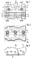
- both a smooth, continuous breast and a corresponding back of the knife are provided in the area of the knife edge to be hardened.
- the new knife is particularly suitable for specially designed planing heads, as described below.
- a planing tool is shown, which is designed as a rotary body, which can preferably be used in an electric motor-driven hand plane. This is done in that the planing tool with the centering recesses 1 indicated in dashed lines in FIGS. 1 and 2, which are provided on the end faces, is placed on corresponding centering pins of the hand plane and is connected in a rotationally fixed manner to a drive with a stub shaft running through the through bore 2 .
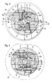
- 1 to 3 consists of a center piece 3 provided with the bore 2, to which two flaps 5 arranged rotationally symmetrically to the longitudinal center plane 4 are connected, each of which is firmly connected to the center piece 3 with three fastening screws 6 and 6 ' .
- the fastening screws 6 engage in the internal thread 7 in the middle piece 3.
- the clamping flaps 5 have circular recesses 8, through which a hexagon socket 9 of the fastening screws 6 can be tightened or loosened.
- the contour of the profile knives 10 corresponds to the outer contour 5a of the clamping flaps 5, but the knives each protrude slightly beyond the flight circle diameter of the clamping flap 5, as can be seen from FIG. 3.
- the middle piece 3 there is also an adjustment thread for adjustment screws 11, which engage with a collar 12 in a groove 13 of the profile knives 10 and are accessible through a further recess 14 for adjustment from the outside. With their help, the position of the profile knife 10 can be adjusted relative to the center piece, as long as the tensioning flap 5 has not yet been tightened.
- the clamping flap 5 itself extends from the associated knife 10 over approximately half the circumference of the planing tool to the chip recess 30 provided for the next planer knife.
- the back 5d facing this chip recess forms part of the chip ejection groove, the bottom of which is from a recess 31 on Center piece 3 is formed.
- each tensioning flap 5 sits positively on the middle piece 3. In the exemplary embodiment, this is done via a fastening bar 5b, which engages in a groove 3b in the middle piece 3, in such a way that a fastening projection 3c on the middle piece 3 and the fastening bar 5b is attacked.
- the tensioning flap 5 is therefore inserted into the groove 3b of the center piece 3 before the fastening screws 6 are inserted into its fastening strip 5b. After the subsequent insertion of the associated profile knife 10, the fastening screws 6 are inserted. Before these are tightened, the profile knives 10 are finely adjusted via the adjusting screws 11, two of which are provided in the exemplary embodiment. After tightening the fastening screws 6, the clamping flaps 5 and the profiled knife 10 are seated firmly and precisely on the middle piece 3. With a screw fastening along a longitudinal plane, a fast, stable fastening of a clamping flap can be achieved, which at the same time forms about half the circumference of the entire planing tool.
- profiling work can be carried out with this planing tool without endangering the operator, because the scope of the tool is adapted to the profile knife used. Nevertheless, a quick conversion to another type of profile knife is possible. For this purpose, only the corresponding profile knives and new tensioning flaps adapted to them are used.
- the cutting edges of the normal planing knives 5c which are designed as reversible knives and are held by guide plates 16, lie on a flight circle 21 which is considerably smaller than the flight circle diameter 22 shown for comparison, on which the outermost cutting parts of the Profile knife 10 lie.
- the recess 31 here forms the chip ejection groove. It is designed for this smallest flight circle diameter.
- the middle piece 3 and the clamping flaps 5, 5 ' can be made from light metal by non-cutting deformation.
- the tensioning flap can then be provided with a steel sheet 20.
- At least two bores 20a are provided in the tensioning flap for the adjusting screws 11 of the planing knife, which bores are arranged perpendicular to the passage bore 8 for the fastening screws 6.
Claims (13)
Priority Applications (1)
| Application Number | Priority Date | Filing Date | Title |
|---|---|---|---|
| AT84104180T ATE27562T1 (de) | 1983-05-24 | 1984-04-13 | Hobelwerkzeug und dafuer geeignetes profilmesser. |
Applications Claiming Priority (4)
| Application Number | Priority Date | Filing Date | Title |
|---|---|---|---|
| DE3318820 | 1983-05-24 | ||
| DE19833318820 DE3318820C2 (de) | 1983-05-24 | 1983-05-24 | Hobelwerkzeug |
| DE19833318799 DE3318799A1 (de) | 1983-05-24 | 1983-05-24 | Hobelmesser, insbesondere profilmesser |
| DE3318799 | 1983-05-24 |
Publications (2)
| Publication Number | Publication Date |
|---|---|
| EP0133197A1 EP0133197A1 (fr) | 1985-02-20 |
| EP0133197B1 true EP0133197B1 (fr) | 1987-06-03 |
Family
ID=25810994
Family Applications (1)
| Application Number | Title | Priority Date | Filing Date |
|---|---|---|---|
| EP84104180A Expired EP0133197B1 (fr) | 1983-05-24 | 1984-04-13 | Outillage à raboter et profilmètre s'y adaptant |
Country Status (3)
| Country | Link |
|---|---|
| US (1) | US4572259A (fr) |
| EP (1) | EP0133197B1 (fr) |
| DE (1) | DE3464022D1 (fr) |
Families Citing this family (7)
| Publication number | Priority date | Publication date | Assignee | Title |
|---|---|---|---|---|
| DE4137623A1 (de) * | 1991-11-15 | 1993-05-19 | Bosch Gmbh Robert | Handhobelmaschine mit rotierendem messertraeger |
| ES2067364B1 (es) * | 1992-06-02 | 1997-02-16 | Margareto Juan Fernandez | Sistema de fijacion de cabezal portacuchillas en maquinas tupi y moldureras para el trabajo de la madera. |
| DE19856278A1 (de) * | 1998-12-07 | 2000-06-08 | Bosch Gmbh Robert | Hobelmesser für Hobelmaschinen, insbesondere Handhobelmaschinen für die Holzbearbeitung |
| GB9903677D0 (en) * | 1999-02-18 | 1999-04-14 | Machell & Sons Ltd W | Method and apparatus for wood board manufacture |
| AT411125B (de) * | 2001-04-12 | 2003-09-25 | Siemens Ag Oesterreich | Halteelement für elektrische bauteile zur montage auf schaltungsträgern |
| IT1395455B1 (it) * | 2009-04-10 | 2012-09-21 | F&P Rusticolegno S R L | Apparecchiatura per la finitura superficiale di manufatti in legno e metodo implementato dalla stessa |
| TWM531893U (zh) * | 2016-06-01 | 2016-11-11 | Shinmax Industry Co Ltd | 刀軸 |
Family Cites Families (16)
| Publication number | Priority date | Publication date | Assignee | Title |
|---|---|---|---|---|
| DE172912C (fr) * | ||||
| DE368930C (de) * | 1923-02-12 | Georg V Hassel | Mit elektrisch leitendem Anstrich arbeitende Vorrichtung zum Ausloesen von Alarm-, Abwehr- und Loeschvorrichtungen bei Zerstoerung von Tueren, Mauern, Schaufenstern u. dgl. | |
| US552435A (en) * | 1895-12-31 | Oe grooving wood | ||
| US203442A (en) * | 1878-05-07 | Improvement in bench-planes | ||
| US1013540A (en) * | 1905-12-14 | 1912-01-02 | Karl Schurz Faucette | Cutter-head. |
| US920549A (en) * | 1907-09-14 | 1909-05-04 | Albert Pryibil | Cutter-head. |
| US1021202A (en) * | 1910-03-31 | 1912-03-26 | Hermance Machine Co | Cutter-head. |
| US1026053A (en) * | 1911-12-19 | 1912-05-14 | Stanley Rule & Level Co | Router-plane cutter. |
| US1150677A (en) * | 1913-11-29 | 1915-08-17 | Crescent Machine Company | Cutter-blade for jointers and planers. |
| US1629760A (en) * | 1926-02-17 | 1927-05-24 | Yates American Machine Co | Cutter head |
| FR807398A (fr) * | 1936-06-18 | 1937-01-11 | Chatelot & Fils A | Rabot à fût métallique |
| US2710635A (en) * | 1953-02-20 | 1955-06-14 | Improved Machinery Inc | Wood chipper |
| CH320043A (de) * | 1954-01-09 | 1957-03-15 | Lennartz & Co | Messerkopf mit zwei Spannbacken mit in Führungsnuten eingesetzten, nachstellbaren Kehlmessern |
| DE2811669C2 (de) * | 1978-03-17 | 1983-11-17 | Karl M. Reich Maschinenfabrik GmbH, 7440 Nürtingen | Hobelkopf mit Wendemessern |
| DE3102065C2 (de) * | 1980-03-08 | 1986-01-09 | Eugen Lutz GmbH u. Co Maschinenfabrik, 7130 Mühlacker | Messerhalterung für Messerwellen oder Messerköpfe |
| EP0048303B1 (fr) * | 1980-10-07 | 1985-06-26 | Black & Decker Inc. | Porte-outil pour robot à main mû par un moteur |
-
1984
- 1984-04-13 DE DE8484104180T patent/DE3464022D1/de not_active Expired
- 1984-04-13 EP EP84104180A patent/EP0133197B1/fr not_active Expired
- 1984-05-11 US US06/609,127 patent/US4572259A/en not_active Expired - Fee Related
Also Published As
| Publication number | Publication date |
|---|---|
| EP0133197A1 (fr) | 1985-02-20 |
| DE3464022D1 (en) | 1987-07-09 |
| US4572259A (en) | 1986-02-25 |
Similar Documents
| Publication | Publication Date | Title |
|---|---|---|
| DE2339873C2 (de) | Anordnung zum Einstellen und Befestigen eines ein Schneidplättchen tragenden Blocks in einer nutförmigen Aufnahme im Werkzeugkörper eines spanabhebenden Werkzeugs | |
| DE2110078A1 (de) | Werkzeug zur spanabhebenden Bear bettung, insbesondere Frasmesserkopf | |
| DE3211766A1 (de) | Schlitzschneider | |
| CH616611A5 (fr) | ||
| DE1511046B2 (de) | Metallblechform, die stanzmesser traegt | |
| DE69923362T2 (de) | Werkzeug zur spanabhebenden Bearbeitung | |
| EP0133197B1 (fr) | Outillage à raboter et profilmètre s'y adaptant | |
| CH635256A5 (de) | Bohrwerkzeug. | |
| DE3013876C2 (de) | Fräsmesserkopf | |
| DE2941179B1 (de) | Zer?kzeug | |
| DE3004881A1 (de) | Vorrichtung zum abschraegen von kanten an werkstuecken, insbesondere blechen | |
| DE602006000263T2 (de) | Werkzeugspannfutter für eine drehende Maschine | |
| DE2901059C2 (de) | Durch spanlose Verformung hergestellte Bohrschraube | |
| DE3318820C2 (de) | Hobelwerkzeug | |
| DE202006007258U1 (de) | Werkzeug zum Bearbeiten eines Rohrendes | |
| DE2542346B2 (de) | Innenraeumwerkzeug, insbesondere zur herstellung von profilnuten | |
| CH655262A5 (de) | Spannbacke. | |
| DE3232495A1 (de) | Vorrichtung zur kuehlmittelzufuhr zu mit kuehlmittelkanaelen versehenen, rotierenden schneidwerkzeugen fuer die spanende metallbearbeitung, insbesondere bohrwerkzeuge | |
| DE2626151C2 (de) | Zylindrische Messerwelle zur Holzbearbeitung | |
| DE2353371A1 (de) | Messertrommel, insbesondere fuer hackmaschinen zur zerkleinerung von abfaellen | |
| DE3405614C2 (fr) | ||
| DE3802154A1 (de) | Mundstueck zur verwendung bei einschraub- und/oder einsetzgeraeten fuer verbindungselemente | |
| EP0491237A1 (fr) | Tête porte-lames | |
| DE4013050A1 (de) | Messerkopf und hobelwelle fuer abrichte-, dicken- und/oder hand- bzw. heimwerker-hobelmaschinen | |
| DE865094C (de) | Auswechselbarer Stahlhalter, insbesondere fuer Drehstaehle |
Legal Events
| Date | Code | Title | Description |
|---|---|---|---|
| PUAI | Public reference made under article 153(3) epc to a published international application that has entered the european phase |
Free format text: ORIGINAL CODE: 0009012 |
|
| AK | Designated contracting states |
Designated state(s): AT BE CH DE FR GB IT LI LU NL SE |
|
| RAP1 | Party data changed (applicant data changed or rights of an application transferred) |
Owner name: BLACK & DECKER OVERSEAS AG Owner name: EUGEN LUTZ + CO. |
|
| 17P | Request for examination filed |
Effective date: 19850820 |
|
| 17Q | First examination report despatched |
Effective date: 19860917 |
|
| GRAA | (expected) grant |
Free format text: ORIGINAL CODE: 0009210 |
|
| AK | Designated contracting states |
Kind code of ref document: B1 Designated state(s): AT BE CH DE FR GB IT LI LU NL SE |
|
| REF | Corresponds to: |
Ref document number: 27562 Country of ref document: AT Date of ref document: 19870615 Kind code of ref document: T |
|
| ITF | It: translation for a ep patent filed |
Owner name: JACOBACCI & PERANI S.P.A. |
|
| REF | Corresponds to: |
Ref document number: 3464022 Country of ref document: DE Date of ref document: 19870709 |
|
| ET | Fr: translation filed | ||
| PLBE | No opposition filed within time limit |
Free format text: ORIGINAL CODE: 0009261 |
|
| STAA | Information on the status of an ep patent application or granted ep patent |
Free format text: STATUS: NO OPPOSITION FILED WITHIN TIME LIMIT |
|
| PG25 | Lapsed in a contracting state [announced via postgrant information from national office to epo] |
Ref country code: LU Free format text: LAPSE BECAUSE OF NON-PAYMENT OF DUE FEES Effective date: 19880430 |
|
| 26N | No opposition filed | ||
| PGFP | Annual fee paid to national office [announced via postgrant information from national office to epo] |
Ref country code: SE Payment date: 19900313 Year of fee payment: 7 |
|
| PGFP | Annual fee paid to national office [announced via postgrant information from national office to epo] |
Ref country code: LU Payment date: 19900329 Year of fee payment: 7 |
|
| PGFP | Annual fee paid to national office [announced via postgrant information from national office to epo] |
Ref country code: GB Payment date: 19900331 Year of fee payment: 7 |
|
| PGFP | Annual fee paid to national office [announced via postgrant information from national office to epo] |
Ref country code: AT Payment date: 19900402 Year of fee payment: 7 |
|
| ITTA | It: last paid annual fee | ||
| PGFP | Annual fee paid to national office [announced via postgrant information from national office to epo] |
Ref country code: NL Payment date: 19900430 Year of fee payment: 7 |
|
| PGFP | Annual fee paid to national office [announced via postgrant information from national office to epo] |
Ref country code: BE Payment date: 19900515 Year of fee payment: 7 |
|
| PGFP | Annual fee paid to national office [announced via postgrant information from national office to epo] |
Ref country code: CH Payment date: 19900627 Year of fee payment: 7 |
|
| PG25 | Lapsed in a contracting state [announced via postgrant information from national office to epo] |
Ref country code: GB Effective date: 19910413 Ref country code: AT Effective date: 19910413 |
|
| PG25 | Lapsed in a contracting state [announced via postgrant information from national office to epo] |
Ref country code: SE Effective date: 19910414 |
|
| PG25 | Lapsed in a contracting state [announced via postgrant information from national office to epo] |
Ref country code: LI Effective date: 19910430 Ref country code: CH Effective date: 19910430 Ref country code: BE Effective date: 19910430 |
|
| BERE | Be: lapsed |
Owner name: BLACK & DECKER OVERSEAS A.G. Effective date: 19910430 |
|
| PG25 | Lapsed in a contracting state [announced via postgrant information from national office to epo] |
Ref country code: NL Effective date: 19911101 |
|
| GBPC | Gb: european patent ceased through non-payment of renewal fee | ||
| NLV4 | Nl: lapsed or anulled due to non-payment of the annual fee | ||
| REG | Reference to a national code |
Ref country code: CH Ref legal event code: PL |
|
| EUG | Se: european patent has lapsed |
Ref document number: 84104180.9 Effective date: 19911108 |
|
| PGFP | Annual fee paid to national office [announced via postgrant information from national office to epo] |
Ref country code: FR Payment date: 19950313 Year of fee payment: 12 |
|
| PGFP | Annual fee paid to national office [announced via postgrant information from national office to epo] |
Ref country code: DE Payment date: 19950324 Year of fee payment: 12 |
|
| PG25 | Lapsed in a contracting state [announced via postgrant information from national office to epo] |
Ref country code: FR Effective date: 19961227 |
|
| PG25 | Lapsed in a contracting state [announced via postgrant information from national office to epo] |
Ref country code: DE Effective date: 19970101 |
|
| REG | Reference to a national code |
Ref country code: FR Ref legal event code: ST |