EP0133197B1 - Planing tool and profile cutter suitable therefor - Google Patents
Planing tool and profile cutter suitable therefor Download PDFInfo
- Publication number
- EP0133197B1 EP0133197B1 EP84104180A EP84104180A EP0133197B1 EP 0133197 B1 EP0133197 B1 EP 0133197B1 EP 84104180 A EP84104180 A EP 84104180A EP 84104180 A EP84104180 A EP 84104180A EP 0133197 B1 EP0133197 B1 EP 0133197B1
- Authority
- EP
- European Patent Office
- Prior art keywords
- planing tool
- knife
- tool according
- groove
- clamping
- Prior art date
- Legal status (The legal status is an assumption and is not a legal conclusion. Google has not performed a legal analysis and makes no representation as to the accuracy of the status listed.)
- Expired
Links
Images
Classifications
-
- B—PERFORMING OPERATIONS; TRANSPORTING
- B27—WORKING OR PRESERVING WOOD OR SIMILAR MATERIAL; NAILING OR STAPLING MACHINES IN GENERAL
- B27G—ACCESSORY MACHINES OR APPARATUS FOR WORKING WOOD OR SIMILAR MATERIALS; TOOLS FOR WORKING WOOD OR SIMILAR MATERIALS; SAFETY DEVICES FOR WOOD WORKING MACHINES OR TOOLS
- B27G13/00—Cutter blocks; Other rotary cutting tools
- B27G13/08—Cutter blocks; Other rotary cutting tools in the shape of disc-like members; Wood-milling cutters
- B27G13/10—Securing the cutters, e.g. by clamping collars
-
- B—PERFORMING OPERATIONS; TRANSPORTING
- B27—WORKING OR PRESERVING WOOD OR SIMILAR MATERIAL; NAILING OR STAPLING MACHINES IN GENERAL
- B27G—ACCESSORY MACHINES OR APPARATUS FOR WORKING WOOD OR SIMILAR MATERIALS; TOOLS FOR WORKING WOOD OR SIMILAR MATERIALS; SAFETY DEVICES FOR WOOD WORKING MACHINES OR TOOLS
- B27G13/00—Cutter blocks; Other rotary cutting tools
- B27G13/02—Cutter blocks; Other rotary cutting tools in the shape of long arbors, i.e. cylinder cutting blocks
- B27G13/04—Securing the cutters by mechanical clamping means
Definitions
- the invention relates to a planing tool with at least two planing knives, which are arranged symmetrically to a common axis of rotation and are each fastened by a flap to a common and driven center piece, which is pressed against the center piece by fastening screws.
- Planing tools of this type are known in the form of folding shafts.
- the flaps consist of segments separated from the middle section, which are held firmly by the fastening screws on the middle section and clamp the planing knives between themselves and the middle section.
- Similar designs are also known for planing heads, which are only shorter in the axial direction than flap shafts.
- a disadvantage of known planing tools is that only tools or knives could be clamped which protrude a maximum of about 1 mm in circumference of the plane body flight circle or could be adjusted to this position.
- the safety standards for all tools in which the workpieces are fed by hand also stipulate that the tool protrudes from the body.
- the invention has for its object to provide a safety-related planing head that is particularly suitable for profile work.
- each flap starting from the associated planing knife, extends over the circumferential area which extends to the chip ejection groove of the next planing knife and is held in a form-fitting manner on the center piece at its end facing away from the associated planing knife.
- This configuration makes it possible to assign a flap designed in a certain way to each planing knife, so that the entire circumference of the planing tool is adapted to the profile to be machined, without the knife edge or a deflector protruding outwards and without having to use separate planing heads.
- the flaps are held at two points in the planing tool and can therefore be arranged over a much larger circumferential area than was the case with known flaps.
- the connection of a form-fitting attachment with the known screw attachment leads, despite the easy interchangeability of the knives and flaps, to a stable cohesion of the parts of the new planing tool, which due to this configuration can not only be used for profiling work that was previously not possible with hand planers.
- the invention makes it possible to adapt the clamping flaps to the flight circle of the associated tool and their end to the subsequent planer knife as part of the chip ejection groove, so that they can be changed together with the required tool on the planer head.
- the planing tool therefore enables a whole range of machining processes that could previously only be carried out with special machines and not at the installation site.
- the form fit between the flap and the middle piece can be achieved in a particularly simple manner in that each flap engages behind a fastening projection on the middle piece with a fastening claw arranged at its end.
- This fastening claw can be designed as a fastening claw as a fastening strip which is inserted axially into a groove lying behind the fastening projection. The new flap is therefore pushed axially onto the center piece and sits securely and stably on the center piece after attachment by the assigned screws.
- the tensioning flap is provided with a steel sheet which can also cover the outer surface of the flap facing the knife. It will then be possible to manufacture both the center piece of the planing tool and the flap from light metal, for example from aluminum or aluminum alloy, without the clamping surface becoming too soft and being damaged during use.
- the steel sheet can be processed very easily together with the aluminum or another material and can be inserted when the flap is cast, for example.
- the fastening screws extend through openings in the planer knife, at the same time a groove running parallel to the plane in which the central axes of the openings lie is provided on the side of the openings facing away from the knife edge, into which the collar of the Engage adjusting screws.
- This embodiment also has the advantage that the planer knife has no weakening in the area of the cutting edge and in the adjacent clamping area due to an adjustment groove or other openings.
- the clamping points of the planing head also remain unaffected by the arrangement of holes or guides flows and can only be designed for the clamping effect.
- the groove is arranged on the chest of the knife so that the collar of the adjusting screws can engage the knife from the inside of the planing head, where there is more space for accommodating the adjusting screws.
- the groove can also run continuously over the length of the knife, which is then inserted in a simple manner from the end face of the planing head, the groove, which is preferably provided with a rectangular cross section, being pushed over the corresponding collar.
- the new knives can also be easily manufactured.
- both a smooth, continuous breast and a corresponding back of the knife are provided in the area of the knife edge to be hardened.
- the new knife is particularly suitable for specially designed planing heads, as described below.
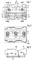
- a planing tool is shown, which is designed as a rotary body, which can preferably be used in an electric motor-driven hand plane. This is done in that the planing tool with the centering recesses 1 indicated in dashed lines in FIGS. 1 and 2, which are provided on the end faces, is placed on corresponding centering pins of the hand plane and is connected in a rotationally fixed manner to a drive with a stub shaft running through the through bore 2 .
- 1 to 3 consists of a center piece 3 provided with the bore 2, to which two flaps 5 arranged rotationally symmetrically to the longitudinal center plane 4 are connected, each of which is firmly connected to the center piece 3 with three fastening screws 6 and 6 ' .
- the fastening screws 6 engage in the internal thread 7 in the middle piece 3.
- the clamping flaps 5 have circular recesses 8, through which a hexagon socket 9 of the fastening screws 6 can be tightened or loosened.
- the contour of the profile knives 10 corresponds to the outer contour 5a of the clamping flaps 5, but the knives each protrude slightly beyond the flight circle diameter of the clamping flap 5, as can be seen from FIG. 3.
- the middle piece 3 there is also an adjustment thread for adjustment screws 11, which engage with a collar 12 in a groove 13 of the profile knives 10 and are accessible through a further recess 14 for adjustment from the outside. With their help, the position of the profile knife 10 can be adjusted relative to the center piece, as long as the tensioning flap 5 has not yet been tightened.
- the clamping flap 5 itself extends from the associated knife 10 over approximately half the circumference of the planing tool to the chip recess 30 provided for the next planer knife.
- the back 5d facing this chip recess forms part of the chip ejection groove, the bottom of which is from a recess 31 on Center piece 3 is formed.
- each tensioning flap 5 sits positively on the middle piece 3. In the exemplary embodiment, this is done via a fastening bar 5b, which engages in a groove 3b in the middle piece 3, in such a way that a fastening projection 3c on the middle piece 3 and the fastening bar 5b is attacked.
- the tensioning flap 5 is therefore inserted into the groove 3b of the center piece 3 before the fastening screws 6 are inserted into its fastening strip 5b. After the subsequent insertion of the associated profile knife 10, the fastening screws 6 are inserted. Before these are tightened, the profile knives 10 are finely adjusted via the adjusting screws 11, two of which are provided in the exemplary embodiment. After tightening the fastening screws 6, the clamping flaps 5 and the profiled knife 10 are seated firmly and precisely on the middle piece 3. With a screw fastening along a longitudinal plane, a fast, stable fastening of a clamping flap can be achieved, which at the same time forms about half the circumference of the entire planing tool.
- profiling work can be carried out with this planing tool without endangering the operator, because the scope of the tool is adapted to the profile knife used. Nevertheless, a quick conversion to another type of profile knife is possible. For this purpose, only the corresponding profile knives and new tensioning flaps adapted to them are used.
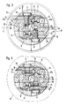
- the cutting edges of the normal planing knives 5c which are designed as reversible knives and are held by guide plates 16, lie on a flight circle 21 which is considerably smaller than the flight circle diameter 22 shown for comparison, on which the outermost cutting parts of the Profile knife 10 lie.
- the recess 31 here forms the chip ejection groove. It is designed for this smallest flight circle diameter.
- the middle piece 3 and the clamping flaps 5, 5 ' can be made from light metal by non-cutting deformation.
- the tensioning flap can then be provided with a steel sheet 20.
- At least two bores 20a are provided in the tensioning flap for the adjusting screws 11 of the planing knife, which bores are arranged perpendicular to the passage bore 8 for the fastening screws 6.
Landscapes
- Life Sciences & Earth Sciences (AREA)
- Engineering & Computer Science (AREA)
- Mechanical Engineering (AREA)
- Wood Science & Technology (AREA)
- Forests & Forestry (AREA)
- Details Of Cutting Devices (AREA)
- Milling, Drilling, And Turning Of Wood (AREA)
Description
Die Erfindung betrifft ein Hobelwerkzeug mit mindestens zwei Hobelmessern, die symmetrisch zu einer gemeinsamen Rotationsachse angeordnet und durch je eine Klappe an einem gemeinsamen und angetriebenen Mittelstück befestigt sind, die durch Befestigungsschrauben gegen das Mittelstück gedrückt wird.The invention relates to a planing tool with at least two planing knives, which are arranged symmetrically to a common axis of rotation and are each fastened by a flap to a common and driven center piece, which is pressed against the center piece by fastening screws.
Hobelwerkzeuge dieser Art sind in der Form von Klappwellen bekannt. Die Klappen bestehen dabei aus von dem Mittelstück getrennten Segmenten, die durch die Befestigungsschrauben fest am Mittelstück gehalten werden und zwischen sich und dem Mittelstück die Hobelmesser einklemmen. Ähnliche Ausgestaltungen sind auch für Hobelköpfe bekannt, die lediglich in axialer Richtung kürzer als Klappenwellen ausgebildet sind.Planing tools of this type are known in the form of folding shafts. The flaps consist of segments separated from the middle section, which are held firmly by the fastening screws on the middle section and clamp the planing knives between themselves and the middle section. Similar designs are also known for planing heads, which are only shorter in the axial direction than flap shafts.
Nachteilig ist bei bekannten Hobelwerkzeugen, dass nur Werkzeuge bzw. Messer eingespannt werden konnten, welche den Hobelkörperflugkreis im Maximum um etwa 1 mm im Umfang überragen bzw. auf diese Position eingestellt werden konnten. Insbesondere wegen der Unfallgefahr ist auch durch die Sicherheitsnormen bei allen Werkzeugen, bei welchen die Werkstücke von Hand zugeführt werden, der Werkzeugüberstand zum Körper vorgeschrieben.A disadvantage of known planing tools is that only tools or knives could be clamped which protrude a maximum of about 1 mm in circumference of the plane body flight circle or could be adjusted to this position. In particular because of the risk of accidents, the safety standards for all tools in which the workpieces are fed by hand also stipulate that the tool protrudes from the body.
Es ist zwar bekannt (DE-OS 3102065), profilierte Hobelmesser bei sogenannten Keilwellen vorzusehen, die mit Abweisern kombiniert werden, damit die Messerkante nicht mehr als ca. 1 mm vorsteht. Nachteilig ist aber, dass die Abweiser die Finger der Bedienungsperson erfassen können.It is known (DE-OS 3102065) to provide profiled planing knives in so-called spline shafts, which are combined with deflectors so that the knife edge does not protrude more than approx. 1 mm. However, it is disadvantageous that the deflectors can grip the operator's fingers.
Der Erfindung liegt die Aufgabe zugrunde, einen sicherheitstechnisch verbesserten Hobelkopf zu schaffen, der insbesondere für Profilarbeiten optimal geeignet ist.The invention has for its object to provide a safety-related planing head that is particularly suitable for profile work.
Die Erfindung besteht bei dem Hobelwerkzeug der eingangs genannten Art darin, dass sich jede Klappe ausgehend von dem zugeordneten Hobelmesser über jeweils den Umfangsbereich erstreckt, der bis zur Späneauswurfnut des nächsten Hobelmessers reicht und an ihrem vom zugeordneten Hobelmesser abgewandten Ende formschlüssig an dem Mittelstück gehalten ist. Diese Ausgestaltung ermöglicht es, jedem Hobelmesser eine in bestimmter Weise gestaltete Klappe zuzuordnen, so dass der gesamte Umfang des Hobelwerkzeuges dem zu bearbeitenden Profil angepasst ist, ohne dass die Messerkante oder ein Abweiser nach aussen übersteht und ohne dass gesonderte Hobelköpfe verwendet werden müssen. Die Klappen sind bei dem Hobelwerkzeug an zwei Stellen gehalten und lassen sich deshalb über einen weit grösseren Umfangsbereich anordnen, als das bei bekannten Klappen der Fall war. Die Verbindung einer formschlüssigen Befestigung mit der bekannten Schraubbefestigung führt trotz leichter Auswechselbarkeit der Messer und Klappen zu einem stabilen Zusammenhalt der Teile des neuen Hobelwerkzeuges, das sich aufgrund dieser Ausgestaltung nicht nur für Profilierungsarbeiten einsetzen lässt, die bisher nicht mit Handhobelmaschinen möglich waren. Durch die Erfindung wird es möglich, die Spannklappen jeweils an den Flugkreis des zugeordneten Werkzeuges und ihr Ende dem nachfolgenden Hobelmesser als Teil der Späneauswurfnut anzupassen, so dass sie zusammen mit dem erforderlichen Werkzeug am Hobelkopf gewechselt werden können. Durch das Hobelwerkzeug sind daher eine ganze Reihe von Bearbeitungsvorgängen möglich, die bisher nur mit Spezialmaschinen und nicht am Einbauort ausgeführt werden konnten.In the case of the planing tool of the type mentioned at the outset, the invention starts from the fact that each flap, starting from the associated planing knife, extends over the circumferential area which extends to the chip ejection groove of the next planing knife and is held in a form-fitting manner on the center piece at its end facing away from the associated planing knife. This configuration makes it possible to assign a flap designed in a certain way to each planing knife, so that the entire circumference of the planing tool is adapted to the profile to be machined, without the knife edge or a deflector protruding outwards and without having to use separate planing heads. The flaps are held at two points in the planing tool and can therefore be arranged over a much larger circumferential area than was the case with known flaps. The connection of a form-fitting attachment with the known screw attachment leads, despite the easy interchangeability of the knives and flaps, to a stable cohesion of the parts of the new planing tool, which due to this configuration can not only be used for profiling work that was previously not possible with hand planers. The invention makes it possible to adapt the clamping flaps to the flight circle of the associated tool and their end to the subsequent planer knife as part of the chip ejection groove, so that they can be changed together with the required tool on the planer head. The planing tool therefore enables a whole range of machining processes that could previously only be carried out with special machines and not at the installation site.
Der Formschluss zwischen Klappe und Mittelstück lässt sich in besonders einfacher Weise dadurch erreichen, dass jede Klappe mit einer an ihrem Ende angeordneten Befestigungsklaue einen Befestigungsvorsprung am Mittelstück hintergreift. Diese Befestigungsklaue kann als eine Befestigungsklaue kann als eine Befestigungsleiste ausgebildet sein, die axial in eine hinter dem Befestigungsvorsprung liegende Nut eingeschoben ist. Die neue Klappe wird daher axial auf das Mittelstück aufgeschoben und sitzt nach der Befestigung durch die zugeordneten Schrauben fest und stabil am Mittelstück.The form fit between the flap and the middle piece can be achieved in a particularly simple manner in that each flap engages behind a fastening projection on the middle piece with a fastening claw arranged at its end. This fastening claw can be designed as a fastening claw as a fastening strip which is inserted axially into a groove lying behind the fastening projection. The new flap is therefore pushed axially onto the center piece and sits securely and stably on the center piece after attachment by the assigned screws.
Vorteilhaft ist es auch, wenn die Spannklappe mit einem Stahlblatt versehen ist, das auch die dem Messer zugewandten Aussenfläche der Klappe überdecken kann. Es wird dann nämlich möglich, sowohl das Mittelstück des Hobelwerkzeuges als auch die Klappe aus Leichtmetall, beispielsweise aus Aluminium oder Aluminium-Legierung herzustellen, ohne dass die Einspannfläche zu weich wird und beim Einsatz beschädigt werden kann. Das Stahlblatt lässt sich zusammen mit dem Aluminium oder einem anderen Werkstoff sehr leicht verarbeiten und kann beispielsweise beim Guss der Klappe mit eingelegt werden.It is also advantageous if the tensioning flap is provided with a steel sheet which can also cover the outer surface of the flap facing the knife. It will then be possible to manufacture both the center piece of the planing tool and the flap from light metal, for example from aluminum or aluminum alloy, without the clamping surface becoming too soft and being damaged during use. The steel sheet can be processed very easily together with the aluminum or another material and can be inserted when the flap is cast, for example.
Vorteilhaft ist es schliesslich auch, wenn in der Klappe mindestens zwei Bohrungen vorhanden sind, die etwa senkrecht zu der Bohrung für die Befestigungsschraube verlaufen, durch die Verstellschrauben zur Radialverstellung des Hobelmessers betätigt werden können.Finally, it is also advantageous if there are at least two bores in the flap, which run approximately perpendicular to the bore for the fastening screw, through which adjusting screws for radial adjustment of the planing knife can be actuated.
Zum Zwecke der einfachen Verstellung des Hobelmessers reichen die Befestigungsschrauben durch Öffnungen im Hobelmesser hindurch, gleichzeitig ist auf der von der Messerschneide abgewandten Seite der Öffnungen eine parallel zu der Ebene, in der die Mittelachsen der Öffnungen liegen, verlaufende Nut vorgesehen, in die die Kragen der Verstellschrauben eingreifen. Durch diese Ausgestaltung ist es möglich, umlaufende und bei der Bewegung der Verstellschrauben mitgenommene Kragen in den Bereich des Fusses des Messers zu verlegen. Die Verstellschrauben selbst können dann in einfacher Weise ebenfalls von der von den Messerschneiden abgewandten Seite des Hobelkopfes her durch entsprechende Öffnungen betätigt werden.For the purpose of easy adjustment of the planer knife, the fastening screws extend through openings in the planer knife, at the same time a groove running parallel to the plane in which the central axes of the openings lie is provided on the side of the openings facing away from the knife edge, into which the collar of the Engage adjusting screws. With this configuration, it is possible to move all-round collars that are carried during the movement of the adjusting screws into the area of the base of the knife. The adjustment screws themselves can then also be actuated in a simple manner from the side of the planing head facing away from the knife edges through corresponding openings.
Diese Ausführungsart weist auch den Vorteil auf, dass das Hobelmesser im Bereich der Schneide und in dem angrenzenden Einspannbereich keinerlei Schwächung durch eine Verstellnut oder sonstige Öffnungen aufweist. Auch die Einspannstellen des Hobelkopfes bleiben von der Anordnung von Bohrungen oder Führungen unbeeinflusst und können ausschliesslich auf den Einspanneffekt ausgelegt werden. Vorteilhaft ist es, wenn die Nut auf der Brust des Messers angeordnet ist, damit der Kragen der Verstellschrauben von der Innenseite des Hobelkopfes her am Messer angreifen kann, wo mehr Platz für die Unterbringung der Verstellschrauben vorhanden ist. Die Nut kann schliesslich auch durchgehend über die Länge des Messers verlaufen, das dann in einfacher Weise von der Stirnseite des Hobelkopfes her eingeschoben wird, wobei die vorzugsweise mit einem rechteckigen Querschnitt versehene Nut über den entsprechenden Kragen geschoben wird. Die neuen Messer lassen sich bei einer solchen Ausbildung auch leicht herstellen. Insbesondere ist im Bereich der zu härtenden Messerschneide sowohl eine glatte durchgehende Brust, als auch ein entsprechender Rücken des Messers vorgesehen. Das neue Messer eignet sich besonders für speziell ausgebildete Hobelköpfe, wie sie im folgenden beschrieben werden.This embodiment also has the advantage that the planer knife has no weakening in the area of the cutting edge and in the adjacent clamping area due to an adjustment groove or other openings. The clamping points of the planing head also remain unaffected by the arrangement of holes or guides flows and can only be designed for the clamping effect. It is advantageous if the groove is arranged on the chest of the knife so that the collar of the adjusting screws can engage the knife from the inside of the planing head, where there is more space for accommodating the adjusting screws. Finally, the groove can also run continuously over the length of the knife, which is then inserted in a simple manner from the end face of the planing head, the groove, which is preferably provided with a rectangular cross section, being pushed over the corresponding collar. With such training, the new knives can also be easily manufactured. In particular, both a smooth, continuous breast and a corresponding back of the knife are provided in the area of the knife edge to be hardened. The new knife is particularly suitable for specially designed planing heads, as described below.
In der Zeichnung ist die Erfindung anhand eines Ausführungsbeispieles dargestellt und in der nachfolgenden Beschreibung erläutert. Es zeigen:
- Fig. 1 eine Ansicht eines erfindungsgemässen Hobelkopfes mit eingesetzten Profilmessern und zugeordneten Spannklappen,
- Fig. 2 die Ansicht des Hobelkopfes der Fig. 1 in Richtung des Pfeiles.1I der Fig. 1,
- Fig. 3 eine vergrösserte Darstellung des Schnittes längs der Linie 111-111 in Fig. 1.
- Fig. 4 einen Schnitt längs der Linie IV-IV, jedoch mit anstelle der Profilmesser eingesetzten Normal-Hobelmessern und
- Fig. 5 eine Ansicht des neuen Profilmessers, das in den Hobelkopf der Fig. 3 eingesetzt ist.
- 1 is a view of a planing head according to the invention with inserted profile knives and associated clamping flaps,
- 2 shows the view of the planing head of FIG. 1 in the direction of
arrow 11 of FIG. 1, - 3 is an enlarged view of the section along the line 111-111 in Fig. 1st
- Fig. 4 shows a section along the line IV-IV, but with normal planing knives used in place of the profile knives and
- Fig. 5 is a view of the new profile knife, which is inserted into the planing head of Fig. 3.
In den Fig. 1 bis 3 ist ein Hobelwerkzeug gezeigt, das als Rotationskörper ausgebildet ist, der vorzugsweise in einen elektromotorisch angetriebenen Handhobel eingesetzt werden kann. Das geschieht dadurch, dass das Hobelwerkzeug mit den in den Fig. 1 und 2 gestrichelt angedeuteten Zentrierausnehmungen 1, die an den Stirnseiten vorgesehen sind, auf entsprechende Zentrierzapfen des Handhobels gesetzt und mit einer durch die durchgehende Bohrung 2 verlaufenden Steckwelle rotationsfest mit einem Antrieb verbunden wird.1 to 3, a planing tool is shown, which is designed as a rotary body, which can preferably be used in an electric motor-driven hand plane. This is done in that the planing tool with the centering
Das Hobelwerkzeug der Fig. 1 bis 3 besteht aus einem mit der Bohrung 2 versehenen Mittelstück 3, mit dem zwei rotationssymmetrisch zu der Längsmittelebene 4 angeordnete Spannklappen 5 verbunden sind, die jeweils mit drei Befestigungsschrauben 6 bzw. 6' mit dem Mittelstück 3 fest verbunden sind. Die Befestigungsschrauben 6 greifen dabei in Innengewinde 7 im Mittelstück 3 ein. Die Spannklappen 5 besitzen im Ausführungsbeispiel kreisförmige Ausnehmungen 8, durch die jeweils ein Innensechskant 9 der Befestigungsschrauben 6 angezogen bzw. gelöst werden können.1 to 3 consists of a
Die Spannklappen 5, die im Ausführungsbeispiel eine profilierte Aussenkontur 5a besitzen, drücken jeweils ein Profilmesser 10 fest gegen die Anlagefläche 3a des Mittelstückes 3, die senkrecht zu der Achsrichtung der Befestigungsschrauben 6 verläuft. Die Kontur der Profilmesser 10 entspricht der Aussenkontur 5a der Spannklappen 5, die Messer stehen jedoch jeweils etwas über den Flugkreisdurchmesser der Spannklappe 5 vor, wie das anhand von Fig. 3 zu erkennen ist. Im Mittelstück 3 ist ausserdem noch jeweils ein Verstellgewinde für Verstellschrauben 11 vorgesehen, die mit einem Bund 12 in eine Nut 13 der Profilmesser 10 eingreifen und durch eine weitere Aussparung 14 zur Verstellung von aussen zugängig sind. Mit ihrer Hilfe kann die Lage der Profilmesser 10 relativ zum Mittelstück eingestellt werden, so lange die Spannklappe 5 noch nicht festgezogen ist.The
Die Spannklappe 5 selbst erstreckt sich von dem zugeordneten Messer 10 aus über etwa die Hälfte des Umfangs des Hobelwerkzeuges bis zu der für das nächste Hobelmesser vorgesehenen Spanausnehmung 30. Der dieser Spanausnehmung zugewandte Rücken 5d bildet einen Teil der Späneauswurfnut, deren Boden von einer Ausnehmung 31 am Mittelstück 3 gebildet wird. An diesem von der Befestigungsschraube 6 abgewandten Ende sitzt jede Spannklappe 5 formschlüssig am Mittelstück 3. Beim Ausführungsbeispiel geschieht dies über eine Befestigungsleiste 5b, die in eine Nut 3b im Mittelstück 3 eingreift, und zwar so, dass ein Befestigungsvorsprung 3c am Mittelstück 3 und der Befestigungsleiste 5b hintergriffen wird. Die Spannklappe 5 wird also vor dem Einsetzen der Befestigungsschrauben 6 in ihre Befestigungsleiste 5b in die Nut 3b des Mittelstücks 3 eingeschoben. Nach dem anschliessenden Einsetzen der zugeordneten Profilmesser 10 werden die Befestigungsschrauben 6 eingesetzt. Ehe diese festgezogen werden, erfolgt die Feineinstellung der Profilmesser 10 über die Verstellschrauben 11, von denen beim Ausführungsbeispiel zwei vorgesehen sind. Nach dem Festziehen der Befestigungsschrauben 6 sitzen Spannklappen 5 und Profilmesser 10 fest und exakt am Mittelstück 3. Mit einer Schraubbefestigung entlang einer Längsebene kann so eine schnelle stabile Befestigung einer Spannklappe erreicht werden, die hier gleichzeitig etwa die Hälfte des Umfangs des gesamten Hobelwerkzeuges bildet.The
Vorteilhaft ist bei dieser Ausführung des Hobelwerkzeuges, dass mit diesem Hobelwerkzeug Profilierungsarbeiten ohne Gefährdung der Bedienungsperson durchgeführt werden können, weil der Umfang des Werkzeuges dem verwendeten Profilmesser angepasst ist. Trotzdem ist ein schneller Umbau auf eine andere Profilmesserart möglich. Zu diesem Zweck werden lediglich die entsprechenden Profilmesser und daran angepasste neue Spannklappen eingesetzt.It is advantageous with this design of the planing tool that profiling work can be carried out with this planing tool without endangering the operator, because the scope of the tool is adapted to the profile knife used. Nevertheless, a quick conversion to another type of profile knife is possible. For this purpose, only the corresponding profile knives and new tensioning flaps adapted to them are used.
Wie aus Fig. 4 zu erkennen ist, ist es dabei auch möglich, Spannklappen 5' einzusetzen, die nicht profiliert sind. Mit Hilfe dieser Spannklappen 5' lassen sich dann übliche wendbare Hobelmesser 5c halten, die in an sich bekannter Weise über besondere Führungsplatten 16 am Mittelstück 3 geführt sind, die mit Hilfe der Verstellschrauben 11 eingestellt werden können. Die Verankerung und Befestigung der Spannklappen 5' entspricht aber jener der Ausführungsform der Fig. 1 bis 3. Mit einem einzigen Mittelstück, das drehfest mit dem Antrieb beispielsweise eines Handhobels verbunden wird, lassen sich somit verschiedene Hobelwerkzeuge verwirklichen, dadurch, dass jeweits Spannklappen und Hobelmesser ausgetauscht werden, die unter sich angepasst sind.As can be seen from Fig. 4, it is also possible to use flaps 5 'that are not profiled. With the help of these clamping flaps 5 ', customary
Wie aus Fig. 4 hervorgeht, liegen die Schneiden der Normal-Hobelmesser 5c, die als Wendemesser ausgebildet und von Führungsplatten 16 gehalten sind, auf einem Flugkreis 21, der wesentlich kleiner ist als der zum Vergleich eingezeichnete Flugkreisdurchmesser 22, auf dem die äussersten Schneidenteile der Profilmesser 10 liegen. Die Ausnehmung 31 bildet hier die Späneauswurfnut. Sie ist auf diesen kleinsten Flugkreisdurchmesser ausgelegt.As can be seen from FIG. 4, the cutting edges of the
Vorteilhaft ist bei der Ausführung nach Fig. 3, dass ein schneller Umbau auf eine andere Profilmesserart möglich ist. Zu diesem Zweck werden lediglich die entsprechenden Profilmesser und daran angepasste neue Spannklappen eingesetzt. Diese vorteilhafte Montage des neuen Messers ist bedingt durch die Ausbildung des Profilmessers 10 (Fig. 5). Dieses besitzt nämlich die Nut 13 in einem Bereich, der auf der von der Schneide 10a abgewandten Seite der Öffnungen 10b liegt, durch die die Befestigungsschrauben 6 hindurchgeführt sind. Dadurch können die Verstellschrauben 11 von der der Messerschneide 10a abgewandten Seite her zugänglich gemacht werden, was die Einjustierung und die Handhabung des Hobelkopfes wesentlich erleichtert und verbessert. Auch die Stabilität der Messer selbst wird im Bereich der Schneide und-des angrenzenden, eingespannten Bereiches ungeschwächt. Die Nut 13 weist einen rechteckigen Querschnitt auf. Sie lässt sich leicht in das Messer 10 einfügen. Der Kragen 12 der Einstellschraube erhält so ebenfalls eine leichte herstellbare Form.It is advantageous in the embodiment according to FIG. 3 that a quick conversion to another type of profile knife is possible. For this purpose, only the corresponding profile knives and new tensioning flaps adapted to them are used. This advantageous assembly of the new knife is due to the design of the profile knife 10 (Fig. 5). This is because the
Das Mittelstück 3 und die Spannklappen 5, 5' können durch spanlose Verformung aus Leichtmetall hergestellt sein. Die Spannklappe kann dann mit einem Stahlblatt 20 versehen sein.The
In der Spannklappe sind mindestens zwei Bohrungen 20a für die Verstellschrauben 11 des Hobelmessers vorgesehen, welche senkrecht zu der Durchlassbohrung 8 für die Befestigungsschrauben 6 angeordnet sind.At least two
Claims (13)
Priority Applications (1)
| Application Number | Priority Date | Filing Date | Title |
|---|---|---|---|
| AT84104180T ATE27562T1 (en) | 1983-05-24 | 1984-04-13 | PLANING TOOL AND SUITABLE PROFILE KNIFE. |
Applications Claiming Priority (4)
| Application Number | Priority Date | Filing Date | Title |
|---|---|---|---|
| DE19833318799 DE3318799A1 (en) | 1983-05-24 | 1983-05-24 | Plane iron, in particular profiled iron |
| DE3318820 | 1983-05-24 | ||
| DE19833318820 DE3318820C2 (en) | 1983-05-24 | 1983-05-24 | Planing tool |
| DE3318799 | 1983-05-24 |
Publications (2)
| Publication Number | Publication Date |
|---|---|
| EP0133197A1 EP0133197A1 (en) | 1985-02-20 |
| EP0133197B1 true EP0133197B1 (en) | 1987-06-03 |
Family
ID=25810994
Family Applications (1)
| Application Number | Title | Priority Date | Filing Date |
|---|---|---|---|
| EP84104180A Expired EP0133197B1 (en) | 1983-05-24 | 1984-04-13 | Planing tool and profile cutter suitable therefor |
Country Status (3)
| Country | Link |
|---|---|
| US (1) | US4572259A (en) |
| EP (1) | EP0133197B1 (en) |
| DE (1) | DE3464022D1 (en) |
Families Citing this family (7)
| Publication number | Priority date | Publication date | Assignee | Title |
|---|---|---|---|---|
| DE4137623A1 (en) * | 1991-11-15 | 1993-05-19 | Bosch Gmbh Robert | HAND PLANER WITH ROTATING KNIFE CARRIER |
| ES2067364B1 (en) * | 1992-06-02 | 1997-02-16 | Margareto Juan Fernandez | FIXING SYSTEM OF KNIFE HOLDER IN TUPI MACHINES AND MOLDING MACHINES FOR THE WORK OF WOOD. |
| DE19856278A1 (en) * | 1998-12-07 | 2000-06-08 | Bosch Gmbh Robert | Plane iron for planing machine, especially hand-guided plane for wood machining, has concave circular or elliptical blade formed at edge of curved aperture in base body |
| GB9903677D0 (en) * | 1999-02-18 | 1999-04-14 | Machell & Sons Ltd W | Method and apparatus for wood board manufacture |
| AT411125B (en) * | 2001-04-12 | 2003-09-25 | Siemens Ag Oesterreich | HOLDING ELEMENT FOR ELECTRICAL COMPONENTS FOR ASSEMBLY ON CIRCUIT BOARDS |
| IT1395455B1 (en) * | 2009-04-10 | 2012-09-21 | F&P Rusticolegno S R L | EQUIPMENT FOR SURFACE FINISHING OF WOOD MANUFACTURES AND METHOD IMPLEMENTED BY ITSELF |
| TWM531893U (en) * | 2016-06-01 | 2016-11-11 | Shinmax Industry Co Ltd | Spindle cutter head |
Family Cites Families (16)
| Publication number | Priority date | Publication date | Assignee | Title |
|---|---|---|---|---|
| US552435A (en) * | 1895-12-31 | Oe grooving wood | ||
| DE172912C (en) * | ||||
| US203442A (en) * | 1878-05-07 | Improvement in bench-planes | ||
| DE368930C (en) * | 1923-02-12 | Georg V Hassel | With electrically conductive paint working device for triggering alarm, defense and Loeschvorrichtungen in the destruction of doors, walls, shop windows and. like | |
| US1013540A (en) * | 1905-12-14 | 1912-01-02 | Karl Schurz Faucette | Cutter-head. |
| US920549A (en) * | 1907-09-14 | 1909-05-04 | Albert Pryibil | Cutter-head. |
| US1021202A (en) * | 1910-03-31 | 1912-03-26 | Hermance Machine Co | Cutter-head. |
| US1026053A (en) * | 1911-12-19 | 1912-05-14 | Stanley Rule & Level Co | Router-plane cutter. |
| US1150677A (en) * | 1913-11-29 | 1915-08-17 | Crescent Machine Company | Cutter-blade for jointers and planers. |
| US1629760A (en) * | 1926-02-17 | 1927-05-24 | Yates American Machine Co | Cutter head |
| FR807398A (en) * | 1936-06-18 | 1937-01-11 | Chatelot & Fils A | Metal shaft plane |
| US2710635A (en) * | 1953-02-20 | 1955-06-14 | Improved Machinery Inc | Wood chipper |
| CH320043A (en) * | 1954-01-09 | 1957-03-15 | Lennartz & Co | Cutter head with two clamping jaws with adjustable fillet knives inserted in guide grooves |
| DE2811669C2 (en) * | 1978-03-17 | 1983-11-17 | Karl M. Reich Maschinenfabrik GmbH, 7440 Nürtingen | Planer head with reversible knives |
| DE3102065C2 (en) * | 1980-03-08 | 1986-01-09 | Eugen Lutz GmbH u. Co Maschinenfabrik, 7130 Mühlacker | Knife holder for knife shafts or knife heads |
| EP0048303B1 (en) * | 1980-10-07 | 1985-06-26 | Black & Decker Inc. | Cutterhead for a power planer |
-
1984
- 1984-04-13 DE DE8484104180T patent/DE3464022D1/en not_active Expired
- 1984-04-13 EP EP84104180A patent/EP0133197B1/en not_active Expired
- 1984-05-11 US US06/609,127 patent/US4572259A/en not_active Expired - Fee Related
Also Published As
| Publication number | Publication date |
|---|---|
| EP0133197A1 (en) | 1985-02-20 |
| DE3464022D1 (en) | 1987-07-09 |
| US4572259A (en) | 1986-02-25 |
Similar Documents
| Publication | Publication Date | Title |
|---|---|---|
| DE2339873C2 (en) | Arrangement for setting and securing a block carrying a cutting tip in a groove-shaped receptacle in the tool body of a cutting tool | |
| DE2110078A1 (en) | Tool for cutting Bear embedding, especially milling cutter head | |
| DE3211766A1 (en) | SLOT CUTTER | |
| CH616611A5 (en) | ||
| DE1511046B2 (en) | METAL SHEET THAT CARRYING PUNCH KNIVES | |
| DE69923362T2 (en) | Tool for machining | |
| EP0133197B1 (en) | Planing tool and profile cutter suitable therefor | |
| CH635256A5 (en) | DRILLING TOOL. | |
| DE3013876C2 (en) | Milling cutter head | |
| DE2941179B1 (en) | Tool | |
| DE3004881A1 (en) | DEVICE FOR BEVELING EDGES ON WORKPIECES, IN PARTICULAR SHEETS | |
| DE602006000263T2 (en) | Tool chuck for a rotating machine | |
| DE2901059C2 (en) | Drilling screw produced by non-cutting deformation | |
| DE3318820C2 (en) | Planing tool | |
| DE202006007258U1 (en) | Tool for installing pipes in a heating system or water supply line comprises a cutting body, wings with cutting edges, clearance zones axially penetrating the cutting body, a cylindrical sleeve and a drive pin | |
| DE2542346B2 (en) | INTERIOR TOOL, IN PARTICULAR FOR THE PRODUCTION OF PROFILE GROOVES | |
| CH655262A5 (en) | CLAMP. | |
| DE3232495A1 (en) | DEVICE FOR THE COOLANT SUPPLY TO ROTATING CUTTING TOOLS PROVIDED WITH COOLANT CHANNELS FOR THE CUTTING METAL WORKING, IN PARTICULAR DRILLING TOOLS | |
| DE2626151C2 (en) | Cylindrical knife shaft for woodworking | |
| DE2353371A1 (en) | KNIFE DRUM, IN PARTICULAR FOR CHOPPING MACHINES FOR CRUSHING WASTE | |
| DE3405614C2 (en) | ||
| DE3802154A1 (en) | Mouthpiece for use in screwing-in and/or setting-in devices for connecting elements | |
| EP0491237A1 (en) | Cutter head | |
| DE4013050A1 (en) | Cutter-head for hand-held planers - has profiled blades keyed into counter-profiled matching groove-like depression in surface of slots | |
| DE865094C (en) | Interchangeable steel holder, especially for turning bars |
Legal Events
| Date | Code | Title | Description |
|---|---|---|---|
| PUAI | Public reference made under article 153(3) epc to a published international application that has entered the european phase |
Free format text: ORIGINAL CODE: 0009012 |
|
| AK | Designated contracting states |
Designated state(s): AT BE CH DE FR GB IT LI LU NL SE |
|
| RAP1 | Party data changed (applicant data changed or rights of an application transferred) |
Owner name: BLACK & DECKER OVERSEAS AG Owner name: EUGEN LUTZ + CO. |
|
| 17P | Request for examination filed |
Effective date: 19850820 |
|
| 17Q | First examination report despatched |
Effective date: 19860917 |
|
| GRAA | (expected) grant |
Free format text: ORIGINAL CODE: 0009210 |
|
| AK | Designated contracting states |
Kind code of ref document: B1 Designated state(s): AT BE CH DE FR GB IT LI LU NL SE |
|
| REF | Corresponds to: |
Ref document number: 27562 Country of ref document: AT Date of ref document: 19870615 Kind code of ref document: T |
|
| ITF | It: translation for a ep patent filed |
Owner name: JACOBACCI & PERANI S.P.A. |
|
| REF | Corresponds to: |
Ref document number: 3464022 Country of ref document: DE Date of ref document: 19870709 |
|
| ET | Fr: translation filed | ||
| PLBE | No opposition filed within time limit |
Free format text: ORIGINAL CODE: 0009261 |
|
| STAA | Information on the status of an ep patent application or granted ep patent |
Free format text: STATUS: NO OPPOSITION FILED WITHIN TIME LIMIT |
|
| PG25 | Lapsed in a contracting state [announced via postgrant information from national office to epo] |
Ref country code: LU Free format text: LAPSE BECAUSE OF NON-PAYMENT OF DUE FEES Effective date: 19880430 |
|
| 26N | No opposition filed | ||
| PGFP | Annual fee paid to national office [announced via postgrant information from national office to epo] |
Ref country code: SE Payment date: 19900313 Year of fee payment: 7 |
|
| PGFP | Annual fee paid to national office [announced via postgrant information from national office to epo] |
Ref country code: LU Payment date: 19900329 Year of fee payment: 7 |
|
| PGFP | Annual fee paid to national office [announced via postgrant information from national office to epo] |
Ref country code: GB Payment date: 19900331 Year of fee payment: 7 |
|
| PGFP | Annual fee paid to national office [announced via postgrant information from national office to epo] |
Ref country code: AT Payment date: 19900402 Year of fee payment: 7 |
|
| ITTA | It: last paid annual fee | ||
| PGFP | Annual fee paid to national office [announced via postgrant information from national office to epo] |
Ref country code: NL Payment date: 19900430 Year of fee payment: 7 |
|
| PGFP | Annual fee paid to national office [announced via postgrant information from national office to epo] |
Ref country code: BE Payment date: 19900515 Year of fee payment: 7 |
|
| PGFP | Annual fee paid to national office [announced via postgrant information from national office to epo] |
Ref country code: CH Payment date: 19900627 Year of fee payment: 7 |
|
| PG25 | Lapsed in a contracting state [announced via postgrant information from national office to epo] |
Ref country code: GB Effective date: 19910413 Ref country code: AT Effective date: 19910413 |
|
| PG25 | Lapsed in a contracting state [announced via postgrant information from national office to epo] |
Ref country code: SE Effective date: 19910414 |
|
| PG25 | Lapsed in a contracting state [announced via postgrant information from national office to epo] |
Ref country code: LI Effective date: 19910430 Ref country code: CH Effective date: 19910430 Ref country code: BE Effective date: 19910430 |
|
| BERE | Be: lapsed |
Owner name: BLACK & DECKER OVERSEAS A.G. Effective date: 19910430 |
|
| PG25 | Lapsed in a contracting state [announced via postgrant information from national office to epo] |
Ref country code: NL Effective date: 19911101 |
|
| GBPC | Gb: european patent ceased through non-payment of renewal fee | ||
| NLV4 | Nl: lapsed or anulled due to non-payment of the annual fee | ||
| REG | Reference to a national code |
Ref country code: CH Ref legal event code: PL |
|
| EUG | Se: european patent has lapsed |
Ref document number: 84104180.9 Effective date: 19911108 |
|
| PGFP | Annual fee paid to national office [announced via postgrant information from national office to epo] |
Ref country code: FR Payment date: 19950313 Year of fee payment: 12 |
|
| PGFP | Annual fee paid to national office [announced via postgrant information from national office to epo] |
Ref country code: DE Payment date: 19950324 Year of fee payment: 12 |
|
| PG25 | Lapsed in a contracting state [announced via postgrant information from national office to epo] |
Ref country code: FR Effective date: 19961227 |
|
| PG25 | Lapsed in a contracting state [announced via postgrant information from national office to epo] |
Ref country code: DE Effective date: 19970101 |
|
| REG | Reference to a national code |
Ref country code: FR Ref legal event code: ST |