EP0132569B1 - Selbstverriegelnde abnehmbare konische Spitzen für Löt- und Auslötwerkzeuge - Google Patents
Selbstverriegelnde abnehmbare konische Spitzen für Löt- und Auslötwerkzeuge Download PDFInfo
- Publication number
- EP0132569B1 EP0132569B1 EP84106808A EP84106808A EP0132569B1 EP 0132569 B1 EP0132569 B1 EP 0132569B1 EP 84106808 A EP84106808 A EP 84106808A EP 84106808 A EP84106808 A EP 84106808A EP 0132569 B1 EP0132569 B1 EP 0132569B1
- Authority
- EP
- European Patent Office
- Prior art keywords
- tip
- soldering
- coating
- tool
- attachment portion
- Prior art date
- Legal status (The legal status is an assumption and is not a legal conclusion. Google has not performed a legal analysis and makes no representation as to the accuracy of the status listed.)
- Expired - Lifetime
Links
Images


Classifications
-
- B—PERFORMING OPERATIONS; TRANSPORTING
- B23—MACHINE TOOLS; METAL-WORKING NOT OTHERWISE PROVIDED FOR
- B23K—SOLDERING OR UNSOLDERING; WELDING; CLADDING OR PLATING BY SOLDERING OR WELDING; CUTTING BY APPLYING HEAT LOCALLY, e.g. FLAME CUTTING; WORKING BY LASER BEAM
- B23K3/00—Tools, devices or special appurtenances for soldering, e.g. brazing, or unsoldering, not specially adapted for particular methods
- B23K3/02—Soldering irons; Bits
- B23K3/025—Bits or tips
- B23K3/026—Removable soldering bits
-
- B—PERFORMING OPERATIONS; TRANSPORTING
- B23—MACHINE TOOLS; METAL-WORKING NOT OTHERWISE PROVIDED FOR
- B23K—SOLDERING OR UNSOLDERING; WELDING; CLADDING OR PLATING BY SOLDERING OR WELDING; CUTTING BY APPLYING HEAT LOCALLY, e.g. FLAME CUTTING; WORKING BY LASER BEAM
- B23K1/00—Soldering, e.g. brazing, or unsoldering
- B23K1/018—Unsoldering; Removal of melted solder or other residues
-
- B—PERFORMING OPERATIONS; TRANSPORTING
- B23—MACHINE TOOLS; METAL-WORKING NOT OTHERWISE PROVIDED FOR
- B23K—SOLDERING OR UNSOLDERING; WELDING; CLADDING OR PLATING BY SOLDERING OR WELDING; CUTTING BY APPLYING HEAT LOCALLY, e.g. FLAME CUTTING; WORKING BY LASER BEAM
- B23K3/00—Tools, devices or special appurtenances for soldering, e.g. brazing, or unsoldering, not specially adapted for particular methods
- B23K3/02—Soldering irons; Bits
- B23K3/025—Bits or tips
Definitions
- the present invention relates to a soldering or de-soldering tool having a handle, a heating element and an operating end, a tapered tip-receiving bore being formed in the operating end of the tool for accepting a replaceable soldering or de-soldering tip, said tip having a tapered attachment portion to be introduced into the tapered tip-receiving bore of said operating end, and a soldering or de-soldering portion, the tip-receiving bore and the tapered attachment portion of the tip having matching tapers and are both frusto-conical in shape.
- soldering irons have soldering tips, and the majority of soldering irons are adapted to receive replaceable soldering tips.
- Replaceable tips are normally inserted into a tip-receiving bore of a soldering iron and are threaded or fixed in place by a set screw or similar mechanical device. The most common tips are either threaded tips or slip fit tips held in place by nuts or screws.
- soldering irons include a sensor element extending within the iron's tip-receiving bore.
- the sensor element fits within a portion of a permanent or replaceable soldering tip.
- de-soldering tools have replaceable de-soldering tips which are normally screw- threaded to the tool. These tips include a central tubular vacuum passge through which the melted solder is drawn.
- the conventional means of attaching and removing soldering and de-soldering tips from the tool are both expensive and time consuming.
- the threading of the threaded tips and the tip-receiving bore of the tool adds an additional manufacturing cost to the tool and tip.
- conventional slip fit tips require an additional mechanical feature, such as a lock bolt or set screw, to fix the tip in place.
- these mechanical features require additional machinery operations and parts.
- the removal and replacement of these conventional tips is time consuming because of the need to loosen and retighten the mechanical locking features.
- soldering and de-soldering tips in many applications have decreased substantially in size to permit precise soldering.
- the demand for smaller soldering tips increases the expense and problems associated with threaded or slip fit soldering and de-soldering tips and aggravates the problems associated with heat transfer and sealing of threaded and slip fit tips.
- FR-A-508 956 describes a soldering tool wherein additional securing means for the soldering tip are avoided by providing the tool with a tip-receiving bore of frusto-conical shape into which the tip is introduced with an attachment portion which also is frusto-conical in shape. Since the material at the tip-receiving bore consists out of aluminum to obtain a light-weight tool, whereas the tip is made of copper, there is a certain danger that the tip will be separated from the tool if the tool attains a certain temperature. The tip therefore has to be pressed into the tip-receiving bore with considerable force to securedly fix the tip in the bore.
- a further problem with soldering and de-soldering tools having a copper body is the oxidization thereof.
- An oxidization may result in freezing of the tip to the material at the tip-receiving bore.
- EP-A2--0 068 484 it is known from EP-A2--0 068 484 to use a tip having a body of carbon based material.
- the object of the present invention is to provide soldering or de-soldering tool having replaceable soldering and de-soldering tips which can easily be fixed to and removed from the tool without the need for threaded or mechanical connections and which are less expensive to manufacture and are more economical to use.
- the tip may be securedly fixed to the tool by only the manual pressing of the tip into the tip-receiving bore and it further may be removed by simply rotating the tip with respect to the tip-receiving bore.
- the tip is always securedly fixed within the tip receiving bore after heating up, and there is no danger that the tip separates from the tool during operation thereof.
- the replaceable soldering and de-soldering tips are less expensive to manufacture since there is no need for threaded or mechanical connections and a better heat transfer and sealing at the interface of the tip and the respective tool is obtained.
- the soldering or de-soldering tip can, without binding, be sized to snugly fit within the tip-receiving bore of the soldering iron and it further can snugly accept a temperature sensor of a temperature-controlled soldering iron.
- the de-soldering tip further provides a near perfect vacuum seal between the tip and the de-soldering tool.
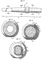
- FIG 1 is a side illustration of one embodiment of a soldering tip made according to the present invention.
- the soldering iron tip shown in Figure 1 and designated generally as numeral 10 includes a shank or attachment portion A, an intermediate portion B adjoining the attachment portion, and a solder-wetting portion C adjoining the intermediate portion.
- the shank or attachment portion A is tapered and frusto-conical in shape and has a length of at least 10% of the total length of the tip.
- the attachment portion has a length of at least 25% of the total length of the tip.
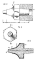
- the shank or attachment portion A is inserted into a tip-receiving bore 32 in the heating element of a soldering iron, as shown generally in Figure 8.
- the tip-receiving bore 32 is also tapered and frusto-conical in shape, and the tip is sized to fit snugly within the tip-receiving bore.
- Both the tip and the tip-receiving bore are tapered at the same angle and are essentially identical in size so that the pressing of the tip into the tip-receiving bore will serve to fix the tip in place without the need of an additional mechanical feature such as a threaded bolt or screw.
- the tip snugly fits within the bore, thereby providing a strong mechanical bond, a good heat transfer interface, and a strong seal.
- An angle of inclination of approximately 3.0 degrees (plus or minus 0.5 degrees) has provided the desired self-locking effect, but it can be shown that a wide range of angles will provide the effect, depending in part upon the materials of the tip and tool and the length of the tip and tip-receiving bore.
- the scope of the invention covers all replaceable tapered soldering or de-soldering tips which can be fixed to a tool with a matching tapered bore of a tool without additional mechanical features.
- the combination of a tapered tip and a matching tapered tip-receiving bore provides good sealing, a strong joint, and very high heat transfer.
- the working end or barrel of the soldering or de-soldering tool can be made from a wide variety of materials, including steel, bronze, brass, aluminum-bronze, and carbon.
- the barrel is made from stainless steel which has good heat conductivity and is resistant to oxidation. Both copper-based and carbon-based tapered tips will lock into the tapered-bore formed in the above materials.
- the barrel of a soldering or de-soldering tool and the respective tip of those tools will expand as the tool and tips are heated and will contract as they cool. Because the barrel of the tool and the tips are often made from different materials, the barrel and the tip may expand and contract to different degrees.
- the co-efficient of heat expansion of stainless steel is 10.1 ⁇ 10 ⁇ ° per degree Centigrade
- of different forms of carbon is between 2.4 to 5.Ox10- 6 per degree Centigrade
- of copper is 17.1 x 10- 6 per degree Centigrade.
- the joint between the tip and tool increases in strength as the tip is heated.
- the tip and tool can be designed so that the attachment portion of the tip has a lower coefficient of heat expansion than that of the heater barrel. The tip can then be more easily removed when the tool and tip are heated.
- the attachment portion of the tip can be coated with different materials to provide the desired heat expansion and contraction effect.
- the soldering tip 10 may include a ferrite iron heat sensing element or "magnestat" 12 fixed to the distal end of the attachment portion A.
- the magnestat contacts with a temperaturesens- ing device in the soldering iron.
- the attachment portion A is preferentially frusto-conical in shape, and the tip 10 tapers generally along the intermediate portion B and the solder-wetting portion C.
- the working end 14 of the tip 10 can be formed in a shape most beneficial to the particular application for which the tip is designed. If desired, the tip can include a shoulder 16 with bevel edges 18. This shoulder serves as a barrier to stop any possible upward flow of solder from the solder-wetting portion C toward the attachment portion A.
- the soldering has an integral body 20.
- the body of the tip can be made from a wide variety of materials, including the conventional copper body.
- the tip has an integral carbon body made, for example, from pure carbon, carbon graphite or pyrolytic carbon.
- Each of these materials have a high carbon content.
- the applicant has found that each of these above carbon-based materials provides an acceptable soldering or de-soldering tip base with sufficient heat conductivity. It is believed that other carbon-based materials, in which the predominant element is carbon, may be likewise acceptable.
- carbon graphite is the preferred carbon body material for most commercial applications.
- Carbon graphite has sufficient heat conductivity and is low in cost.
- Carbon graphite has a thermal conductivity which approximates 60% of the normal thermal conductivity of pure copper and costs 1/3 to 1/5 as much.
- other carbon-based materials may be more appropriate.
- pyrolytic carbon can be fashioned to provide a much better thermal conductivity than copper.
- the cost of pyrolytic carbon is 3-5 times as much as copper.
- a carbon base provides several advantages over copper and other known base materials for soldering and de-soldering tips. If the attachment portion of the tip is left uplated, the heat transfer between the tip and the tool is increased because iron plating added to conventional tips is less heat conductive than carbon. An unplated attachment portion of a carbon-based tip overcomes this problem. Another advantage of a carbon-based tip is that the tapered shank of bare carbon-based material is soft enough that, if the fit between the tip and tip-receiving bore is not perfect, it can be corrected by rotating the tip in the tip-receiving bore several times, thereby removing a small amount of carbon and conforming the shape of the tip to the individual tip-receiving bore.
- Carbon based tips provide further advantages. For example, if the tip does become bound in the tip-receiving bore, the carbon tip can be easily removed by breaking it and reaming the remains out of the tip-receiving bore with a hand reamer, pocket knife or similar tool. In addition, carbon does not dissolve when place in contact with solders. Furthermore, the carbon does not oxidize or react with other elements at high temperatures and does not have a liquid state. Moreover, carbon materials are easily fabricated on standard machine tools, often at lesser costs than copper. Finally, as will be explained below, the carbon base readily accepts platings of metals during a plating process.
- the copper or carbon soldering tip includes a coating of iron 22 formed over the entire exterior body of the tip.
- a coating of nickel plating 24 is formed over the iron coating 22 along the intermediate portion B and the attachment portion A, but not along the solder-wetting portion C.
- a coating 26 of chromium is formed over the nickel plating 24 along the intermediate portion B and the attachment portion A, but not along the solder-wetting portion C.
- the iron coating 22 provides a wettable surface in the working area 14 of the tip.
- the nickel-chrome coating localizes the wettable working surface so that precision soldering can be achieved.
- the nickel-chrome coating also impedes the upward-flow of solder along the intermediate portion B and toward the attachment portion A. Without the coating, solder would flow to the point where the soldering tip and soldering iron meet and might bond the tip and iron together.
- the attachment portion includes the exterior coatings of iron, nickel and chrome. As will be discussed below, it is possible to strip some or all coatings from the attachment portion A so that only nickel coated or uncoated, bare copper or carbon-based material interfaces with the soldering iron.
- a second embodiment of a soldering tip made according to the invention is shown in Figures 4, 5, 6, and 7, wherein like numbers are used to refer to like parts.
- the soldering tip 10 shown in Figure 4 includes an elongated bore 19 formed in the attachment portion A and sized to receive snugly a temperature-sensing element of a soldering iron.
- the soldering tip in Figure 4 is similar to the tip in Figure 1 and includes a copper or carbon body 20, an iron coating 22, a nickel coating 24, and a chrome coating 26.
- the attachment portion A of the tip is tapered and sized to securely fit the tip to the tool by only the manual pressing of the tip into a similarly sized tip-receiving base of the tool.
- the tip includes a thin coating of dull nickel 21 formed between the body 20 and the iron coating 22 along the intermediate portion B and the solder-wetting portion C.
- the primary distinction between the embodiment shown in Figures 1 and 4 is that the attachment portion A does not include any metal coatings in the finished product. Furthermore, there is no coating on the inner surface of the elongated bore 19.
- soldering tip when used with a carbon base, is the present preferred embodiment of the soldering tip made in accordance with the invention. It prevents any possible oxidation or freezing of the attachment portion A to the soldering iron or to the temperature-sensing element of the soldering iron. In addition, it provides the best heat-transfer between the tip and the tool and can be rotated in the tip-receiving bore to improve the fit by slightly wearing away any imperfect surfaces.
- the coating of iron has a thickness in the range of 50.8 to 254 11m (2 to 10 mils)
- the outer coating of nickel has a thickness in the range of 1.27 to 25.4 pm (0.05 to 1 mil)
- the coating of chrome has a thickness in the range of 12.7 to 25.4 pm (0.5 to 1 mil). If an inner coating of dull nickel is used, that coating is approximately (12.7 11m (0.5 mils) thick.
- Figure 8 illustrates an embodiment of the present invention comprising a soldering tip attached to a temperature-controlled soldering iron with a temperature-sensing element.
- the soldering iron includes a general body portion 30 with a tip-receiving bore 32. That tip-receiving bore is frusto-conical in shape and is preferably tapered at an angle of approximately 3.0 degrees (plus or minus 0.5 degrees).
- a sensor element 34 for sensing the temperature of the soldering tip.
- the removable soldering tip 10 is attached to the tool by pressing the tip into the tip-receiving bore. Because of the mating tapers of the tip and the tip-receiving bore, the manual pressing of the tip into the bore will form a joint between the tip and tool. To remove the tip, a wrench or similar tool engages the two opposed flat surfaces 31 and 33, best shown in Figure 1, to rotate the tip approximately 5 degrees which will loosen it for its removal. Thus, it is apparent that the tip can be easily attached and removed from the tool.
- FIGS 9 through 11 illustrate an embodiment of the de-soldering tip 40 and tool made according to the invention.
- the de-soldering tip 40 includes an attachment portion A, an intermediate portion B adjoining the attachment portion A, and a solder-wetting portion C adjoining the intermediate portion B.
- the attachment portion A is frusto-conical in shape and has a length and taper similar to that previously described in reference to the tip of a soldering tool.
- the attachment portion A is sized to fit within a tip-receiving bore 43 of a de-soldering tool.
- the tip 40 includes a central, tubular vacuum passage 42 which aligns with a vacuum tube on the de-soldering tool.
- the materials for the tip and the geometry of the attachment portion of the tip and its attachment to the de-soldering tool are the same as those previously discussed with respect to the soldering tip.
- the tip is heated and then brought into contact with solder which the operator desires to remove from a circuit.
- a vacuum source is connected to the vacuum passage 42 so that after the solder is melted, the melted solder is drawn off through the tube 42.
- the de-soldering tip 40 as shown in Figure 11 has an integral body 46.
- the body 46 can be made of conventional materials such as copper, or can be carbon-based. Similarly, the body can be plated with iron, nickel, and chromium platings in a similar manner and for the same purposes as previously discussed regarding the soldering tip.
- the de-soldering tip is a carbon-based tip having an uncoated attachment portion.
- the wall of tubular vacuum passage 42 is uncoated, bare carbon. The melted solder will not adhere to this carbon and therefore it is unnecessary to plate the passage or place a stainless steel tube in the passage.
- the preferred carbon-based soldering and de-soldering tip of the present invention provides several benefits not found in commercial copper soldering and de-soldering tips.
- the carbon body is not prone to oxidation or dissolving. Because of these characteristics, the carbon body will not cavitate or oxidize at points of discontinuity or wear in the metal coatings.
- the tip of the present invention therefore, eliminates the problems of pitting, heat transfer loss by oxidation, and freezing by oxidation.
- the present invention also provides a longer lasting tip at a lower cost.
- the carbon tip can be coated more quickly than copper, and the porous material of the carbon tip absorbs impurities in the plating baths and results in a more defect-free plating job.
- the self-locking tapered feature of the present invention is less expensive to manufacture and more economical to use since the tips can be easily inserted and removed. It has also been found that the tapered tips transfer heat better than threaded tips and slip fit tips. De-soldering tips made in accordance with the present invention provide a near perfect vacuum seal because the spaces around the tapered sections are small and the taper can be finished very smoothly at a relatively low cost. In addition, tapers are easier to plate smooth.
- a copper or carbon-based tip is machined to the desired shape by a typical machining element such as a lathe or turning machine. It has been found that the preferred carbon materials are easily adaptable to such machining. Due to the production of dust during machining of carbon-based tips, special dust collecting equipment should be used.
- the desired coatings are electroplated on the base by a rack or barrel coating process, or a desired combination of both. Both of these coating processes are well-known in the art. The preferred process depends upon the availability of coating machinery, the number of tips to be produced, and the economics of operation.
- the tips are to be coated by a rack coating process, the tips are first electroplated with a coating of iron through the use of a common iron plating bath, such as iron fluoroborate. Next, a coating of nickel is electroplated over the iron coating, and finally a coating of chrome is electroplated over the nickel coating.
- Plating baths for electroplating nickel and chrome are well-known.
- the nickel and chrome coatings are stripped from the solder-wetting portion of the tip to expose the iron coating as the wetting surface. If desired, the nickel and chrome coatings can also be stripped from the attachment portion of the tip.
- the barrel coating process may be more economical than a rack coating process, particularly if the tips are produced on a large scale. If tips are to be made by the barrel coating process, it is preferable first to place a thin dull coating of nickel over the base by a rack coating process. This thin coating strengthens the pointed end of the tip so it will not break during the barrel coating process. The remaining steps of electroplating iron, nickel and chrome can be made in a barrel coating process. Then, at least the solder-wetting portion is stripped of any nickel or chrome coatings to expose the iron coating as a wetting surface.
- soldering tip shown in Figure 4
- two different procedures are possible. First, it is possible to coat the entire length of the tip and then strip any iron, nickel, and chrome coatings from the attachment portion of the soldering tip. In the alternative, the attachment portion can be masked during the electroplating process so that no coating is initially formed on the attachment portion of the tip.
Landscapes
- Engineering & Computer Science (AREA)
- Mechanical Engineering (AREA)
- Electric Connection Of Electric Components To Printed Circuits (AREA)
- Gripping Jigs, Holding Jigs, And Positioning Jigs (AREA)
- Arc Welding In General (AREA)
Claims (16)
Priority Applications (1)
| Application Number | Priority Date | Filing Date | Title |
|---|---|---|---|
| AT84106808T ATE56381T1 (de) | 1983-06-16 | 1984-06-14 | Selbstverriegelnde abnehmbare konische spitzen fuer loet- und ausloetwerkzeuge. |
Applications Claiming Priority (2)
| Application Number | Priority Date | Filing Date | Title |
|---|---|---|---|
| US06/504,970 US4560101A (en) | 1983-06-16 | 1983-06-16 | Self-locking, removeable tapered tips for soldering and de-soldering tools |
| US504970 | 1983-06-16 |
Publications (3)
| Publication Number | Publication Date |
|---|---|
| EP0132569A2 EP0132569A2 (de) | 1985-02-13 |
| EP0132569A3 EP0132569A3 (en) | 1987-02-04 |
| EP0132569B1 true EP0132569B1 (de) | 1990-09-12 |
Family
ID=24008478
Family Applications (1)
| Application Number | Title | Priority Date | Filing Date |
|---|---|---|---|
| EP84106808A Expired - Lifetime EP0132569B1 (de) | 1983-06-16 | 1984-06-14 | Selbstverriegelnde abnehmbare konische Spitzen für Löt- und Auslötwerkzeuge |
Country Status (9)
| Country | Link |
|---|---|
| US (1) | US4560101A (de) |
| EP (1) | EP0132569B1 (de) |
| JP (1) | JPS6061165A (de) |
| AT (1) | ATE56381T1 (de) |
| AU (1) | AU577048B2 (de) |
| BR (1) | BR8402941A (de) |
| CA (1) | CA1232031A (de) |
| DE (1) | DE3483187D1 (de) |
| HU (1) | HU190872B (de) |
Families Citing this family (23)
| Publication number | Priority date | Publication date | Assignee | Title |
|---|---|---|---|---|
| USD328018S (en) | 1990-03-07 | 1992-07-21 | Esab Welding Products, Inc. | Nozzle for plasma arc torch |
| US5569400A (en) * | 1994-02-28 | 1996-10-29 | Lee; In S. | Soldering gun with U-shaped insertable terminal structure and tip having differing impedance layers |
| DE29600771U1 (de) * | 1996-01-17 | 1997-05-28 | Cooper Industries, Inc., Houston, Tex. | Lötkolben |
| US6386423B1 (en) * | 1997-02-10 | 2002-05-14 | Delaware Capital Formation, Inc. | Soldering iron tips |
| DE29714929U1 (de) * | 1997-08-20 | 1998-12-17 | Cooper Tools GmbH, 74354 Besigheim | Befestigungsvorrichtung |
| JP3221850B2 (ja) * | 1997-10-01 | 2001-10-22 | 中島銅工株式会社 | 加熱用チップおよびその製造方法 |
| AU4186799A (en) * | 1998-05-14 | 1999-11-29 | Plato Products, Inc. | Polished soldering tip and method of manufacturing |
| US7030339B2 (en) * | 2002-11-26 | 2006-04-18 | Hakko Corporation | Soldering iron tip with metal particle sintered member connected to heat conducting core |
| US8237091B2 (en) * | 2002-11-26 | 2012-08-07 | Hakko Corporation | Soldering iron with replaceable tip |
| US20050011876A1 (en) * | 2002-11-26 | 2005-01-20 | Takashi Uetani | Soldering iron with replaceable tip cap |
| FR2851435B1 (fr) | 2003-02-24 | 2006-07-14 | Oreal | Dispositif de conditionnement et d'application d'un produit cosmetique. |
| CN1575900A (zh) | 2003-07-04 | 2005-02-09 | 白光株式会社 | 焊料加热工具 |
| US7699208B2 (en) | 2007-11-30 | 2010-04-20 | Nordson Corporation | Soldering tip, soldering iron, and soldering system |
| JP4896085B2 (ja) * | 2008-07-01 | 2012-03-14 | アポロ精工株式会社 | 半田付け装置 |
| US20100269325A1 (en) * | 2009-04-24 | 2010-10-28 | Hassard Michael P | Snap ring expansion tool and method of use |
| JP5704994B2 (ja) * | 2011-03-31 | 2015-04-22 | インターナショナル・ビジネス・マシーンズ・コーポレーションInternational Business Machines Corporation | 半導体接合装置 |
| DE202014001956U1 (de) * | 2014-02-28 | 2015-05-29 | Weller Tools Gmbh | Lötspitzenbefestigungssystem |
| US9776271B2 (en) * | 2014-12-19 | 2017-10-03 | Hakko Corporation | Desoldering tool nozzle and method of manufacturing the nozzle |
| JP6647817B2 (ja) * | 2015-08-21 | 2020-02-14 | 白光株式会社 | 加熱カートリッジ及び加熱工具 |
| US10307850B2 (en) * | 2017-08-24 | 2019-06-04 | Micron Technology, Inc. | Solder removal from semiconductor devices |
| USD854263S1 (en) * | 2018-01-25 | 2019-07-16 | Guilbert Express | Horn remover for animals |
| USD905770S1 (en) * | 2019-05-16 | 2020-12-22 | Thomas Klamm | Reamer |
| FR3110362B1 (fr) | 2020-05-13 | 2022-05-20 | Pro Am Profession Amenageur | Bureau autoporteur à plateau pliant |
Family Cites Families (13)
| Publication number | Priority date | Publication date | Assignee | Title |
|---|---|---|---|---|
| FR508956A (fr) * | 1918-03-07 | 1920-10-28 | Jean Nadaud | Fer à souder électrique |
| FR875667A (fr) * | 1941-09-30 | 1942-09-30 | Panne pour fer à souder | |
| US2418781A (en) * | 1944-07-17 | 1947-04-08 | George E Lewis | Welding electrode |
| US2763762A (en) * | 1952-03-19 | 1956-09-18 | Sunbeam Corp | Electric dehorner and means for converting same to soldering iron |
| US3120598A (en) * | 1961-04-27 | 1964-02-04 | Siegel | Device for shaping heat softenable materials |
| US3358897A (en) * | 1964-03-31 | 1967-12-19 | Tempress Res Co | Electric lead wire bonding tools |
| US3646577A (en) * | 1970-03-30 | 1972-02-29 | Ncr Co | Temperature-controlled soldering tool |
| JPS523870Y2 (de) * | 1974-06-29 | 1977-01-27 | ||
| JPS5122119A (ja) * | 1974-08-16 | 1976-02-21 | Hitachi Ltd | Setsuzokupaipu |
| JPS51106230A (ja) * | 1975-03-15 | 1976-09-21 | Matsushita Electric Works Ltd | Kanrenketsusochi |
| US4187972A (en) * | 1978-03-28 | 1980-02-12 | Pace Incorporated | Apparatus including general purpose desolderer and means for converting the general purpose desolderer to either a soldering iron or a special purpose desolderer |
| US4424930A (en) * | 1981-06-29 | 1984-01-10 | Cooper Industries, Inc. | Carbon-based soldering and de-soldering tip and method of manufacturing same |
| US6014919A (en) * | 1996-09-16 | 2000-01-18 | Precision Vascular Systems, Inc. | Method and apparatus for forming cuts in catheters, guidewires, and the like |
-
1983
- 1983-06-16 US US06/504,970 patent/US4560101A/en not_active Expired - Fee Related
-
1984
- 1984-06-13 AU AU29319/84A patent/AU577048B2/en not_active Ceased
- 1984-06-14 DE DE8484106808T patent/DE3483187D1/de not_active Expired - Fee Related
- 1984-06-14 AT AT84106808T patent/ATE56381T1/de active
- 1984-06-14 EP EP84106808A patent/EP0132569B1/de not_active Expired - Lifetime
- 1984-06-15 BR BR8402941A patent/BR8402941A/pt not_active IP Right Cessation
- 1984-06-15 CA CA000456726A patent/CA1232031A/en not_active Expired
- 1984-06-15 HU HU842320A patent/HU190872B/hu not_active IP Right Cessation
- 1984-06-16 JP JP59124371A patent/JPS6061165A/ja active Granted
Also Published As
| Publication number | Publication date |
|---|---|
| BR8402941A (pt) | 1985-05-28 |
| US4560101A (en) | 1985-12-24 |
| JPH0472635B2 (de) | 1992-11-18 |
| CA1232031A (en) | 1988-01-26 |
| DE3483187D1 (de) | 1990-10-18 |
| JPS6061165A (ja) | 1985-04-08 |
| EP0132569A2 (de) | 1985-02-13 |
| HUT35568A (en) | 1985-07-29 |
| HU190872B (en) | 1986-11-28 |
| AU2931984A (en) | 1984-12-20 |
| EP0132569A3 (en) | 1987-02-04 |
| ATE56381T1 (de) | 1990-09-15 |
| AU577048B2 (en) | 1988-09-15 |
Similar Documents
| Publication | Publication Date | Title |
|---|---|---|
| EP0132569B1 (de) | Selbstverriegelnde abnehmbare konische Spitzen für Löt- und Auslötwerkzeuge | |
| EP0068484B1 (de) | Löt- und Entlötspitze auf Kohlenstoffbasis und Verfahren zu ihrer Herstellung | |
| US7699208B2 (en) | Soldering tip, soldering iron, and soldering system | |
| KR100449568B1 (ko) | 용접용콘택트팁 | |
| US8569657B2 (en) | Soldering iron with replaceable tip | |
| US4187972A (en) | Apparatus including general purpose desolderer and means for converting the general purpose desolderer to either a soldering iron or a special purpose desolderer | |
| US20050011876A1 (en) | Soldering iron with replaceable tip cap | |
| EP0417468A1 (de) | Schweissapparat, welcher mit einer spritzerfesten und elektrisch leitenden Schicht überzogen ist | |
| US4442182A (en) | One-piece, composite electrical connector | |
| EP0059642B1 (de) | Zusammengesetzte Kohlestäbe zum Fugenhobeln und zum Bearbeiten von metallischen Gegenständen mittels Pressluft und eines elektrischen Lichtbogens | |
| US2679223A (en) | Soldering instrument | |
| US3109231A (en) | Method of producing soldering tips for electric soldering irons | |
| US4000026A (en) | Method and cement for bonding carbon articles | |
| JP3753859B2 (ja) | ハンダ鏝及び鏝先部材 | |
| JP3227420U (ja) | アーク溶接用キャップ式コンタクトチップ | |
| JPH06277849A (ja) | 溶接用ノズル | |
| EP1685922A1 (de) | Lötspitze mit einer Verschleiss- und Korrosionsbeständigen Schutzschicht, welche dispergierte Hartstoffe enthält | |
| JPH1157996A (ja) | こて先部材および半田ごて | |
| US2462002A (en) | Cutting tip for cutting tools | |
| EP0202799A2 (de) | Verfahren zur Herstellung eines hohlen Werkzeuges | |
| JPH0670961U (ja) | はんだごて用こて先 | |
| JPH0723105Y2 (ja) | 半田こて先用ビット | |
| HU188896B (en) | Hand soldering bit and method for producing same | |
| CN101077543A (zh) | 带有抗磨损抗腐蚀涂层的钎焊焊嘴 | |
| MXPA97002412A (en) | Contact point for solder |
Legal Events
| Date | Code | Title | Description |
|---|---|---|---|
| PUAI | Public reference made under article 153(3) epc to a published international application that has entered the european phase |
Free format text: ORIGINAL CODE: 0009012 |
|
| AK | Designated contracting states |
Designated state(s): AT CH DE FR GB IT LI NL |
|
| PUAL | Search report despatched |
Free format text: ORIGINAL CODE: 0009013 |
|
| AK | Designated contracting states |
Kind code of ref document: A3 Designated state(s): AT CH DE FR GB IT LI NL |
|
| RHK1 | Main classification (correction) |
Ipc: B23K 3/02 |
|
| 17P | Request for examination filed |
Effective date: 19870721 |
|
| 17Q | First examination report despatched |
Effective date: 19881215 |
|
| GRAA | (expected) grant |
Free format text: ORIGINAL CODE: 0009210 |
|
| RAP1 | Party data changed (applicant data changed or rights of an application transferred) |
Owner name: COOPER INDUSTRIES, INC. |
|
| AK | Designated contracting states |
Kind code of ref document: B1 Designated state(s): AT CH DE FR GB IT LI NL |
|
| REF | Corresponds to: |
Ref document number: 56381 Country of ref document: AT Date of ref document: 19900915 Kind code of ref document: T |
|
| ITF | It: translation for a ep patent filed | ||
| REF | Corresponds to: |
Ref document number: 3483187 Country of ref document: DE Date of ref document: 19901018 |
|
| ET | Fr: translation filed | ||
| PLBE | No opposition filed within time limit |
Free format text: ORIGINAL CODE: 0009261 |
|
| STAA | Information on the status of an ep patent application or granted ep patent |
Free format text: STATUS: NO OPPOSITION FILED WITHIN TIME LIMIT |
|
| 26N | No opposition filed | ||
| ITTA | It: last paid annual fee | ||
| PGFP | Annual fee paid to national office [announced via postgrant information from national office to epo] |
Ref country code: AT Payment date: 19940519 Year of fee payment: 11 |
|
| PGFP | Annual fee paid to national office [announced via postgrant information from national office to epo] |
Ref country code: FR Payment date: 19940613 Year of fee payment: 11 |
|
| PGFP | Annual fee paid to national office [announced via postgrant information from national office to epo] |
Ref country code: CH Payment date: 19940718 Year of fee payment: 11 |
|
| PGFP | Annual fee paid to national office [announced via postgrant information from national office to epo] |
Ref country code: NL Payment date: 19950425 Year of fee payment: 12 |
|
| PGFP | Annual fee paid to national office [announced via postgrant information from national office to epo] |
Ref country code: GB Payment date: 19950509 Year of fee payment: 12 |
|
| PG25 | Lapsed in a contracting state [announced via postgrant information from national office to epo] |
Ref country code: AT Effective date: 19950614 |
|
| PGFP | Annual fee paid to national office [announced via postgrant information from national office to epo] |
Ref country code: DE Payment date: 19950629 Year of fee payment: 12 |
|
| PG25 | Lapsed in a contracting state [announced via postgrant information from national office to epo] |
Ref country code: LI Effective date: 19950630 Ref country code: CH Effective date: 19950630 |
|
| PG25 | Lapsed in a contracting state [announced via postgrant information from national office to epo] |
Ref country code: FR Effective date: 19960229 |
|
| REG | Reference to a national code |
Ref country code: CH Ref legal event code: PL |
|
| REG | Reference to a national code |
Ref country code: FR Ref legal event code: ST |
|
| PG25 | Lapsed in a contracting state [announced via postgrant information from national office to epo] |
Ref country code: GB Effective date: 19960614 |
|
| PG25 | Lapsed in a contracting state [announced via postgrant information from national office to epo] |
Ref country code: NL Effective date: 19970101 |
|
| GBPC | Gb: european patent ceased through non-payment of renewal fee |
Effective date: 19960614 |
|
| PG25 | Lapsed in a contracting state [announced via postgrant information from national office to epo] |
Ref country code: DE Effective date: 19970301 |
|
| NLV4 | Nl: lapsed or anulled due to non-payment of the annual fee |
Effective date: 19970101 |