EP0202799A2 - Verfahren zur Herstellung eines hohlen Werkzeuges - Google Patents
Verfahren zur Herstellung eines hohlen Werkzeuges Download PDFInfo
- Publication number
- EP0202799A2 EP0202799A2 EP86303276A EP86303276A EP0202799A2 EP 0202799 A2 EP0202799 A2 EP 0202799A2 EP 86303276 A EP86303276 A EP 86303276A EP 86303276 A EP86303276 A EP 86303276A EP 0202799 A2 EP0202799 A2 EP 0202799A2
- Authority
- EP
- European Patent Office
- Prior art keywords
- blank
- external profile
- inductor
- cast
- undersized
- Prior art date
- Legal status (The legal status is an assumption and is not a legal conclusion. Google has not performed a legal analysis and makes no representation as to the accuracy of the status listed.)
- Withdrawn
Links
- 238000004519 manufacturing process Methods 0.000 title claims abstract description 32
- 238000000034 method Methods 0.000 claims abstract description 60
- 239000000463 material Substances 0.000 claims abstract description 55
- 239000011248 coating agent Substances 0.000 claims abstract description 35
- 238000000576 coating method Methods 0.000 claims abstract description 35
- 238000002844 melting Methods 0.000 claims abstract description 21
- 230000008018 melting Effects 0.000 claims abstract description 21
- 238000005266 casting Methods 0.000 claims abstract description 19
- 239000002131 composite material Substances 0.000 claims abstract description 18
- 239000007787 solid Substances 0.000 claims abstract description 12
- 238000010438 heat treatment Methods 0.000 claims abstract description 11
- 239000004020 conductor Substances 0.000 claims abstract description 5
- 230000001939 inductive effect Effects 0.000 claims abstract description 4
- 229910045601 alloy Inorganic materials 0.000 claims description 36
- 239000000956 alloy Substances 0.000 claims description 36
- 230000006698 induction Effects 0.000 claims description 27
- RYGMFSIKBFXOCR-UHFFFAOYSA-N Copper Chemical compound [Cu] RYGMFSIKBFXOCR-UHFFFAOYSA-N 0.000 claims description 20
- 239000010949 copper Substances 0.000 claims description 20
- 229910052802 copper Inorganic materials 0.000 claims description 18
- 238000004070 electrodeposition Methods 0.000 claims description 8
- 239000007788 liquid Substances 0.000 claims description 6
- 239000000126 substance Substances 0.000 claims description 5
- 229910052797 bismuth Inorganic materials 0.000 claims description 3
- JCXGWMGPZLAOME-UHFFFAOYSA-N bismuth atom Chemical compound [Bi] JCXGWMGPZLAOME-UHFFFAOYSA-N 0.000 claims description 3
- 239000004033 plastic Substances 0.000 claims description 3
- 229920003023 plastic Polymers 0.000 claims description 3
- 229910000881 Cu alloy Inorganic materials 0.000 claims description 2
- 229910000990 Ni alloy Inorganic materials 0.000 claims description 2
- 238000011065 in-situ storage Methods 0.000 claims description 2
- 230000000063 preceeding effect Effects 0.000 claims 5
- 239000012811 non-conductive material Substances 0.000 claims 2
- 239000002184 metal Substances 0.000 description 9
- 229910052751 metal Inorganic materials 0.000 description 9
- XLYOFNOQVPJJNP-UHFFFAOYSA-N water Substances O XLYOFNOQVPJJNP-UHFFFAOYSA-N 0.000 description 7
- 230000015572 biosynthetic process Effects 0.000 description 5
- 239000003792 electrolyte Substances 0.000 description 5
- 238000009713 electroplating Methods 0.000 description 5
- 238000003754 machining Methods 0.000 description 5
- 238000009835 boiling Methods 0.000 description 3
- PXHVJJICTQNCMI-UHFFFAOYSA-N Nickel Chemical compound [Ni] PXHVJJICTQNCMI-UHFFFAOYSA-N 0.000 description 2
- 238000010276 construction Methods 0.000 description 2
- 238000001816 cooling Methods 0.000 description 2
- 239000000498 cooling water Substances 0.000 description 2
- 238000000151 deposition Methods 0.000 description 2
- 230000008021 deposition Effects 0.000 description 2
- 238000004090 dissolution Methods 0.000 description 2
- 238000000227 grinding Methods 0.000 description 2
- 229910001092 metal group alloy Inorganic materials 0.000 description 2
- 150000002739 metals Chemical class 0.000 description 2
- 238000012360 testing method Methods 0.000 description 2
- 241000870659 Crassula perfoliata var. minor Species 0.000 description 1
- 239000002253 acid Substances 0.000 description 1
- 150000007513 acids Chemical class 0.000 description 1
- 239000000654 additive Substances 0.000 description 1
- 238000013019 agitation Methods 0.000 description 1
- 238000005275 alloying Methods 0.000 description 1
- 238000013459 approach Methods 0.000 description 1
- 238000005219 brazing Methods 0.000 description 1
- 238000003486 chemical etching Methods 0.000 description 1
- 239000000470 constituent Substances 0.000 description 1
- 230000008602 contraction Effects 0.000 description 1
- 238000007796 conventional method Methods 0.000 description 1
- 238000005520 cutting process Methods 0.000 description 1
- 238000009760 electrical discharge machining Methods 0.000 description 1
- 238000010291 electrical method Methods 0.000 description 1
- 238000002848 electrochemical method Methods 0.000 description 1
- 238000011049 filling Methods 0.000 description 1
- 239000004519 grease Substances 0.000 description 1
- 238000003780 insertion Methods 0.000 description 1
- 230000037431 insertion Effects 0.000 description 1
- 230000001788 irregular Effects 0.000 description 1
- 238000011068 loading method Methods 0.000 description 1
- 238000010297 mechanical methods and process Methods 0.000 description 1
- 239000000155 melt Substances 0.000 description 1
- 239000012528 membrane Substances 0.000 description 1
- 239000007769 metal material Substances 0.000 description 1
- 239000002480 mineral oil Substances 0.000 description 1
- 235000010446 mineral oil Nutrition 0.000 description 1
- 229910052759 nickel Inorganic materials 0.000 description 1
- 238000010422 painting Methods 0.000 description 1
- 229920000642 polymer Polymers 0.000 description 1
- -1 special Substances 0.000 description 1
- 238000004381 surface treatment Methods 0.000 description 1
- 238000012546 transfer Methods 0.000 description 1
- 239000001993 wax Substances 0.000 description 1
Images

Classifications
-
- B—PERFORMING OPERATIONS; TRANSPORTING
- B22—CASTING; POWDER METALLURGY
- B22D—CASTING OF METALS; CASTING OF OTHER SUBSTANCES BY THE SAME PROCESSES OR DEVICES
- B22D19/00—Casting in, on, or around objects which form part of the product
- B22D19/06—Casting in, on, or around objects which form part of the product for manufacturing or repairing tools
-
- B—PERFORMING OPERATIONS; TRANSPORTING
- B22—CASTING; POWDER METALLURGY
- B22D—CASTING OF METALS; CASTING OF OTHER SUBSTANCES BY THE SAME PROCESSES OR DEVICES
- B22D19/00—Casting in, on, or around objects which form part of the product
-
- B—PERFORMING OPERATIONS; TRANSPORTING
- B22—CASTING; POWDER METALLURGY
- B22D—CASTING OF METALS; CASTING OF OTHER SUBSTANCES BY THE SAME PROCESSES OR DEVICES
- B22D25/00—Special casting characterised by the nature of the product
Definitions
- This invention relates to a method of making a hollow working tool for the treatment of a predetermined shaped portion of a workpiece, the tool having a predetermined external profile which corresponds generally with the shaped portion of the workpiece which is to be treated by the working tool.
- the present invention has been developed primarily, though not exclusively, in relation to the manufacture of a hollow inductor for use in an induction hardening machine.
- Inductors are used for hardening workpieces made of metals and metal alloys.
- the term "inductor” is used to define an actual element, through which electrical current passes, and a magnetic intensifier incorporated in the inductor, to cause eddy currents to be induced in the adjacent metal of the workpiece.
- the method of this invention is particularly suitable for making inductors to be used for the hardening of gear teeth, though it should be understood that the method has many other applications for making hollow working tools for the treatment of a predetermined shaped portion of a workpiece, in which the tool is formed with a predetermined external profile which corresponds generally with the shaped portion of the workpiece which is to be treated by the working tool.
- the method has applciation in the manufacture of hollow conductors of intricate construction and closely toleranced dimensions, when required.
- An induction hardening machine which includes an inductor which is caused to traverse along the gap defined between an adjacent pair of gear teeth of a gear in order to carry out induction hardening.
- the process is carried out according to a carefully controlled set of operating parameters, in order to achieve the formation of a surface-hardened layer along the working surfaces of the gear teeth, which provides enhanced operating performance of the gear wheel so as to be able to operate satisfactorily for prolonged periods of time under arduous loading conditions.
- One of the crucial parameters in a successful operation of the process concerns the size and positioning of the inductor within the gear tooth space.
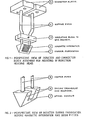
- Figure 1 is a perspective view of the inductor and a connector block assembly for mounting in an induction heating head.
- Figure 2 is a perspective view of the inductor during fabrication, but before a magnetic intensifier has been fitted therein.
- Figure 3 is a sectional elevation showing the arrangement of the inductor as it traverses along the gear tooth space, and also shows the clearances at the root and along the flanks of the adjacent gear teeth which define the gear tooth space.
- FIG. 1 shows an inductor which comprises a copper fabrication 1 enclosing a magnetic intensifier 2.
- the inductor is supported via copper pipes 4 from connector blocks 5, which may be secured to the induction heating head (not shown) of the apparatus.
- the size of the inductor will be determined by the tooth gap space defined between a pair of adjacent teeth of a gear wheel which is to receive induction hardening, and necessarily the inductor 1 will be of a relatively small size.
- the inductor is shown in an enlarged perspective view in Figure 2, which illustrates the complexity of the copper fabrication 1, which obviously gives rise to considerable manufacturing difficulties of assembly for the actual size (smaller) of the inductor than that shown in Figure 2.
- the inductor basically comprises two hollow triangular end sections 6 whciha re connected at their apices by a conduit 7.
- Annealed copper plate is used for the manufacture, as copper is the preferred material of construction in order to conduct the high level of alternating current required for induction heating.
- the entire fabrication is hollow so that the cooling water can pass down one pipe 8, via one end section 6, apical conduit 7, second end section 6 and out via the second copper pipe 8.
- the leakage of cooling water from the inductor cannot be tolerated.
- the present invention has been developed primarily with a view to providing an improved method of manufacture of an inductor for use in an induction hardening method and apparatus, though the invention is not limited to manufacture of such hollow working tools, and has application to the manufacture of other hollow working tools in which it is necessary to provide a carefully controlled predetermined external profile.
- a method of making a hollow working tool for the treatment of a predetermined shaped portion of a workpiece the tool having a predetermined external profile which corresponds generally with the shaped portion of the workpiece which is to be treated by the working tool, and the method comprising:
- the coating is made of a material having a significantly higher melting point than that of the cast solid blank, and the cast material is removed from the composite structure by the application of sufficient heat to melt the cast material, which may then be poured out of the composite structure.
- the coating it is not essential for the coating to have much higher melting point than the case material and other means than the application of heat material and other means than the application of heat may be employed in order to remove the cast material e.g. chemical means, which selectively dissolve the cast material and leaves the thick coating substantially intact.
- the thick metallic coating is applied by electrodeposition, in which case conveniently the cast material which forms the blank is metallic.
- electrodeposition is not the only means which may be adopted to form the thick metallic coating.
- the cast material does not have to be metallic, as other materials, such as specialised electrically conductive plastics materials, may be used as the core on which the electrodeposition of the metallic coating takes place.
- the cast material may even be non-conductive, provided that a conductive film is applied onto its external surface in order to promote electrodeposition of the coating thereon.
- the method according to the invention is particularly, though not exclusively, suitable for making a hollow workign tool in the form of a hollow inductor for use in an induction hardening machine.
- a method of making a hollow inductor for use in inductive heat treatment of a predetermined shaped portion of a workpiece by traversing the inductor along the surface of the shaped portion, the inductor having an external profile which corresponds generally with the shaped portion of the workpiece, and the method comprising:
- the method according to the further aspect of the invention is particularly useful in making a hollow inductor for use in induction hardening of gear teeth to provide surface hardening of the working surfaces of the gear teeth, and also to a significant depth below the surface, in which the inductor is caused to traverse along the gap defined between each pair of adjacent teeth during the induction hardening process.
- An inductor made by the method according to the further aspect of the invention can have its external profile made to accurate requirements concerning clearances between the external profile of the inductor and the flank and root surfaces of the gear teeth, which is one of a number of important parameters to be carefully controlled, to achieve satisfactory surface hardening, as taught by the disclosure in GB specification No. 2 143 854A.
- the blank is cast in situ in the gap defined between a typical pair of adjacent gear teeth of the gear which is to be induction hardened.
- the material from which the blank is cast is an alloy having a melting point in the range 70 to 80°C, so that the cast material can readily be removed from the composite structure - (formed by application of the metallic coating thereon) by the use of very hot water.
- One preferred method of making a hollow inductor for use in induction hardening machines comprises the following steps:
- the working surface of the component which is to be treated by the inductor may be covered with a lining, prior to casting of the blank therein, to reduce the amount of cast material which has to be removed to form the undersized blank.
- the lining is of variable thickness and/or held out of contact with the working surfaces of the component, to further reduce the amount of cast material which has to be removed from the blank in the formation of the undersized blank.
- the material from which the blank is cast is an alloy having a melting point in the range of 70 to 80°C in the preferred method referred to above, and conveniently an alloy based on the metal bismuth may be used. Alloys with a melting point in the range of 70 to 80°C will be molten in very hot water, thereby facilitating the subsequent removal of the cast material from the composite structure.
- the blank is electroplated with a metallic coating of copper or copper/nickel alloy.
- the electroplating may be done in alternating layers of copper and copper/nickel to improve the electrical and/or mechanical properties.
- the blank which is actually electroplated may be composed of more than one blank which has been cast and/or otherwise produced separately, and subsequently joined together in an electrically conductive manner. Furthermore, sections of the blank may be removed, to produce the required shape of blank which is to be electroplated.
- Figures 1 to 3 there is shown an inductor which is suitable for use in the induction hardening method and apparatus which is disclosed in more detail in our published GB specification No. 2 143 854A. Figures 1 to 3 have already been described in more detail in the introduction to this specification.
- the inductor 1 there is first formed, by casting, a solid blank which has an external profile which corresponds generally with the required external profile of the inductor, the blank being (a) cast in a shape having an external provile which is undersized in a predetermined manner relative to the required external profile of the inductor or (b) subsequently reduced in size so as to provide this undersized external profile.
- a thick metallic coating is applied so as to provide a composite structure having an external profile which corresponds, or which is subsequently worked so as to correspond with the required external profile of the inductor.
- the coating is made of a material having a significantly higher melting point that that of the cast solid blank, and is of sufficient thickness to provide a rigid structure, upon subsequent removal of the material forming the cast blank. Thereafter, the cast material is heated to liquid form and then is removed from the composite structure, thereby forming the hollow inductor with the required external profile.
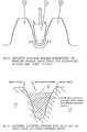
- FIG. 4 there is shown the formation of a cast solid alloy blank B in the tooth space defined between a pair of adjacent gear teeth 10 of a gear which is to be induction hardened.
- the blank B is cast in a low melting point alloy, and a range of low melting point alloys is well known, the exact melting point being determined by varying the proportions of the alloying constituents.
- an alloy having a melting point of 70 to 80° is ideal, and alloys having melting points in this range are frequently based on the metal bismuth.
- An alloy with a melting point in this range will be molten in very hot water.
- the blank B with a profile of the gear tooth space can be obtained by placing blanking plates at each end of the tooth space, and filling the casting mould formed thereby with a molten alloy of the type referred to above.
- Figure 4 is a sectional elevation of the results achieved by this casting process. It is not necessary to use a space on the actual gear to form the casting mould. Frequently, "test arcs" of teeth are machined in order to ascertain the exact parameters for hardening, prior to hardening the actual gear wheel. One of the spaces on a test arc could readily be used instead, to form the required casting mould. Alternatively, a piece of another material, e. g. a non-metallic substance, such as Tufnol (Registered Trade Mark) could be specially prepared on the gear cutting machine to give the required profile, for use as the casting mould. It may be appropriately undersized, if required.
- Tufnol Registered Trade Mark
- the blank B is removed from the gear tooth space. It is probable that differential contraction on cooling will break the bond between alloy and gear teeth, but if this is not the case, a gentle tap on the end of the blank should serve equally well.
- Surface treatment of the gear teeth e. g. polish, grease, etc. may also be used to facilitate the removal of the blank.
- the casting may be performed at an intermediate stage in the machining process.
- the volume of alloy which must subsequently be removed may be reduced to a minimum.
- the tooth space 11 of an essentially finished machined gear may be lined with a lining membrane 12, as shown in Figure 5.
- the lining 12 may be metallic, e.g. an annealed copper sheet bent, and gently worked to the profile of the gear teeth 10.
- lining 12 may be moved away from the addendum of gear teeth 10, e.g. by wedges 13 as shown in Figure 6.
- Non-metallic linings 12 could also be used.
- the thickness of lining 12 would be such as to minimise subsequent alloy-removal from the blank.
- the alloy When the alloy has solidified and been removed from the gear space, it will be reduced in size, if necessary, to the final dimensions by one, or more of the methods previously outlined.
- the advantages of casting the alloy along the full width of a gear tooth are that several blanks makes it easier to hold during machining operations.
- One method of alloy removal after casting could be:-
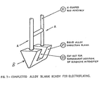
- rods will be cast from the same alloy.
- the rods will be cast in an 'H' section (20, Figure 7), using conventional techniques, i.e. running liquid alloy into a hot mould, allowing to cool and separating the two halves of the mould to remove the casting.
- the H-shaped rod assembly 20 may be fitted by pushing the ends of the rods into the holes previously drilled in the blanks. The rods are then secured into the holes by careful use of a cool brazing torch. Alternatively, an artist's paint brush, dipped in boiling water and then applied to the joint may well create sufficient local heating to fuse the two components.
- Figure 7 shows the completed alloy blank. The cut out 22 is for subsequent insertion of the magnetic intensifier 2 ( Figure 1).
- the completed alloy block ( Figure 7) is now placed in a bath of electrolyte and plated with copper.
- a chemical etching is sometimes used before electroplating to clean the alloy surfce and so encourage deposition of a uniformly thick layer.
- the blank is a metallic alloy it will be electrically conducting.
- the cross bar on the H-shaped rod assembly 20 serves two functions. They are firstly to provide rigidity to the two vertical rods and secondly to improve the flow of electrical current over the blank so that a more uniform deposition takes place.
- various known techniques may be adopted to obtain a coating of as uniform a thickness as possible. Such techniques could include the use of multiple anodes, agitation of the electrolyte, special, additives in the electrolyte, specially chosen current densities, etc.
- the block is removed from the electrolyte, washed and checked dimensionally.
- the copper surface of the inductor is now smoothed to remove 'high points' and give the final dimensions. This operation would probably be done carefully by a craftsman using a file or scraper; however, as the copper surface is well supported, careful handling on, for example a grinding wheel, may be possible.
- the magnetic intensifier (2) may be fitted and smoothed to the final dimensions at the same time as the rest of the inductor.
- the H-shaped rods 20 are cut-off along the plane AA.
- the component is now placed in boiling water and allowed to thoroughly heat through.
- the alloy When the alloy has melted, it may be run out via one of the copper pipes which have formed around the H-shaped rods 20. It is possible that gentle air or water pressure may have to be applied to one copper pipe, in order to cause the molten alloy to run out of the other.
- the inductor Once the inductor is free of alloy, it will be pressure tested to check for leaks and dimensionally checked. It will then be incorporated into the complete inductor assembly, as shown in Figure 1.
- inductors may be more easily, cheaply and accurately manufactured than by the existing fabrication techniques.
- inductors for helically cut teeth could be made as easily as those for cross-cut teeth, whereas the fabrication method would be much more complex for helically cut teeth.
- smaller inductors could be made with the fabrication method, so extending downwards the size range of gears which can be hardened by the method and apparatus disclosed in our GB specification No. 2 143 854A.
- the cast blank B is made of electrically conductive material, to enable the subsequent application of the metallic coating thereon by electrodeposition, this is not essential to the invention.
- electrically conductive casting materials may be used, such as speciallised electrically conductive plastics material.
- non-conductive cast materials may be used, such as waxes and polymers, provided that an electrically conductive film is applied thereon, to form a cathode surface on which the electrodeposited metallic coating may be applied.
Landscapes
- Engineering & Computer Science (AREA)
- Mechanical Engineering (AREA)
- Manufacturing & Machinery (AREA)
- Heat Treatment Of Articles (AREA)
Applications Claiming Priority (2)
| Application Number | Priority Date | Filing Date | Title |
|---|---|---|---|
| GB08512168A GB2175921A (en) | 1985-05-14 | 1985-05-14 | Electroformed tool |
| GB8512168 | 1985-05-14 |
Publications (1)
| Publication Number | Publication Date |
|---|---|
| EP0202799A2 true EP0202799A2 (de) | 1986-11-26 |
Family
ID=10579101
Family Applications (1)
| Application Number | Title | Priority Date | Filing Date |
|---|---|---|---|
| EP86303276A Withdrawn EP0202799A2 (de) | 1985-05-14 | 1986-04-30 | Verfahren zur Herstellung eines hohlen Werkzeuges |
Country Status (6)
| Country | Link |
|---|---|
| EP (1) | EP0202799A2 (de) |
| JP (1) | JPS61270336A (de) |
| KR (1) | KR860008820A (de) |
| AU (1) | AU5736186A (de) |
| FI (1) | FI861928A7 (de) |
| GB (1) | GB2175921A (de) |
Cited By (2)
| Publication number | Priority date | Publication date | Assignee | Title |
|---|---|---|---|---|
| CN104451096A (zh) * | 2014-12-09 | 2015-03-25 | 唐山大隆机械制造有限责任公司 | 用于连续曲面工件淬火的可随动回转的淬火感应器 |
| CN112055793A (zh) * | 2018-05-08 | 2020-12-08 | 索尼公司 | 柔性齿轮的制造方法、柔性齿轮单元的制造方法以及齿轮 |
Families Citing this family (1)
| Publication number | Priority date | Publication date | Assignee | Title |
|---|---|---|---|---|
| CN113290231B (zh) * | 2021-05-31 | 2022-07-05 | 华中科技大学 | 消失模铸造液液复合铝镁双金属的方法及铝镁双金属 |
Family Cites Families (12)
| Publication number | Priority date | Publication date | Assignee | Title |
|---|---|---|---|---|
| GB1063098A (en) * | 1964-06-03 | 1967-03-30 | Herbert Fernyhough Maddocks | Improvements in heat exchangers |
| GB1061684A (en) * | 1965-04-22 | 1967-03-15 | Simmonds Precision Products | An improved method for the manufacture of thin metal tubes |
| GB1249972A (en) * | 1967-09-22 | 1971-10-13 | Plessey Co Ltd | Improvements in or relating to fluidics devices |
| US3560350A (en) * | 1968-10-01 | 1971-02-02 | Budd Co | Irregular shaped tubing formed by electrodeposition |
| GB1455872A (en) * | 1973-05-25 | 1976-11-17 | Boc International Ltd | Cutting nozzles |
| US3939046A (en) * | 1975-04-29 | 1976-02-17 | Westinghouse Electric Corporation | Method of electroforming on a metal substrate |
| GB1542939A (en) * | 1976-06-01 | 1979-03-28 | Plessey Co Ltd | Manufacture of hollow metallic structures by electrodeposition |
| DE2828993C2 (de) * | 1978-07-01 | 1984-04-12 | Kernforschungszentrum Karlsruhe Gmbh, 7500 Karlsruhe | Verfahren zur galvanoplastischen Herstellung eines Düsenkörpers |
| JPS593152B2 (ja) * | 1979-05-30 | 1984-01-23 | 株式会社リコー | 微細孔形成方法 |
| US4326928A (en) * | 1981-01-26 | 1982-04-27 | General Dynamics, Pomona Division | Method of electroforming |
| US4428801A (en) * | 1982-09-30 | 1984-01-31 | General Dynamics, Pomona Division | Method and device for providing shaped electroformed parts using shrinkable tube members |
| GB2167444B (en) * | 1984-11-22 | 1988-05-25 | Risis Private Limited | Electroforming |
-
1985
- 1985-05-14 GB GB08512168A patent/GB2175921A/en not_active Withdrawn
-
1986
- 1986-04-30 EP EP86303276A patent/EP0202799A2/de not_active Withdrawn
- 1986-05-08 FI FI861928A patent/FI861928A7/fi not_active Application Discontinuation
- 1986-05-12 AU AU57361/86A patent/AU5736186A/en not_active Abandoned
- 1986-05-14 JP JP61110449A patent/JPS61270336A/ja active Pending
- 1986-05-14 KR KR1019860003756A patent/KR860008820A/ko not_active Withdrawn
Cited By (3)
| Publication number | Priority date | Publication date | Assignee | Title |
|---|---|---|---|---|
| CN104451096A (zh) * | 2014-12-09 | 2015-03-25 | 唐山大隆机械制造有限责任公司 | 用于连续曲面工件淬火的可随动回转的淬火感应器 |
| CN112055793A (zh) * | 2018-05-08 | 2020-12-08 | 索尼公司 | 柔性齿轮的制造方法、柔性齿轮单元的制造方法以及齿轮 |
| US12222029B2 (en) | 2018-05-08 | 2025-02-11 | Sony Corporation | Method of manufacturing flexible gear, method of manufacturing flexible gear unit, and gear |
Also Published As
| Publication number | Publication date |
|---|---|
| FI861928A7 (fi) | 1986-11-15 |
| KR860008820A (ko) | 1986-12-18 |
| JPS61270336A (ja) | 1986-11-29 |
| GB2175921A (en) | 1986-12-10 |
| FI861928A0 (fi) | 1986-05-08 |
| GB8512168D0 (en) | 1985-06-19 |
| AU5736186A (en) | 1987-01-22 |
Similar Documents
| Publication | Publication Date | Title |
|---|---|---|
| US3352770A (en) | Electrochemical machining of small diameter holes in high temperature superalloys | |
| EP1521657B2 (de) | Verfahren zur Herstellung eines metallischen Werkstücks | |
| DE69200134T2 (de) | Verfahren zum Auftragen von Hartlötlegierung auf Basismetalloberflächen mittels elektrischer Entladungen. | |
| JP3694354B2 (ja) | 電気機械のステータコイルロッドの中空の導体エレメントへの冷却液の給排のため及び電流接続のために働く接続装置を修復する方法 | |
| DE3544123C2 (de) | ||
| CA1179023A (en) | Method for welding railroad rails and means therefor | |
| DE2633829A1 (de) | Verfahren zum verbinden von metallteilen mittels lichtbogen- schmelzschweissen | |
| Rennie et al. | Electroforming of rapid prototyping mandrels for electro-discharge machining electrodes | |
| US20190177872A1 (en) | Electrolytic polishing method and device and method for producing a cathode | |
| EP0202799A2 (de) | Verfahren zur Herstellung eines hohlen Werkzeuges | |
| JP3241936B2 (ja) | 絶縁材料の放電加工方法 | |
| RU2325257C2 (ru) | Способ производства металлического изделия, металлическое изделие, способ соединения металлических деталей и конструкция с соединением | |
| Brown | Modern manufacturing processes | |
| EP0561571B1 (de) | Schweissverfahren | |
| EP0264936A2 (de) | Verfahren zur Herstellung einer Verbundstahlwelle | |
| CN1125649A (zh) | 电渣熔铸导叶工艺方法及设备 | |
| CN208019574U (zh) | 一种电火花放电加工机电极块 | |
| US3550259A (en) | Nipple or nozzle buildup by the electroslag consumable nozzle technique | |
| JP2003201591A (ja) | 電着ドラムとその製造方法 | |
| US2775811A (en) | Methods for forming contact surfaces | |
| US3322185A (en) | Method of making electrical discharge machining electrodes | |
| US3316626A (en) | Method of making an airfoil shaped electrode | |
| Bocking et al. | Relationships Between Wall Thickness and Erosion Depth of Thin Walled Electroformed EDM Electrodes Produced From RP Models 469 | |
| RU2071858C1 (ru) | Способ изготовления штампов | |
| Lobanov et al. | Influence of parameters of electrodynamic treatment on residual stresses of welded joints of alloy AMg6 |
Legal Events
| Date | Code | Title | Description |
|---|---|---|---|
| PUAI | Public reference made under article 153(3) epc to a published international application that has entered the european phase |
Free format text: ORIGINAL CODE: 0009012 |
|
| AK | Designated contracting states |
Kind code of ref document: A2 Designated state(s): CH DE FR GB IT LI NL SE |
|
| STAA | Information on the status of an ep patent application or granted ep patent |
Free format text: STATUS: THE APPLICATION HAS BEEN WITHDRAWN |
|
| 18W | Application withdrawn |
Withdrawal date: 19870629 |
|
| RIN1 | Information on inventor provided before grant (corrected) |
Inventor name: ALLDREAD, MICHAEL DAVID |