EP0130438B1 - Isolierverglasungskonstruktion - Google Patents
Isolierverglasungskonstruktion Download PDFInfo
- Publication number
- EP0130438B1 EP0130438B1 EP84106856A EP84106856A EP0130438B1 EP 0130438 B1 EP0130438 B1 EP 0130438B1 EP 84106856 A EP84106856 A EP 84106856A EP 84106856 A EP84106856 A EP 84106856A EP 0130438 B1 EP0130438 B1 EP 0130438B1
- Authority
- EP
- European Patent Office
- Prior art keywords
- glass
- spacer
- sealed unit
- unit
- section
- Prior art date
- Legal status (The legal status is an assumption and is not a legal conclusion. Google has not performed a legal analysis and makes no representation as to the accuracy of the status listed.)
- Expired
Links
- 125000006850 spacer group Chemical group 0.000 title claims description 128
- 239000011521 glass Substances 0.000 claims description 158
- 239000000565 sealant Substances 0.000 claims description 34
- 150000001875 compounds Chemical class 0.000 claims description 10
- 238000003780 insertion Methods 0.000 claims description 7
- 230000037431 insertion Effects 0.000 claims description 7
- 229920002367 Polyisobutene Polymers 0.000 claims description 3
- 229920005549 butyl rubber Polymers 0.000 claims description 2
- 238000010276 construction Methods 0.000 description 14
- 239000000463 material Substances 0.000 description 11
- 238000000034 method Methods 0.000 description 11
- RAPBNVDSDCTNRC-UHFFFAOYSA-N Chlorobenzilate Chemical compound C=1C=C(Cl)C=CC=1C(O)(C(=O)OCC)C1=CC=C(Cl)C=C1 RAPBNVDSDCTNRC-UHFFFAOYSA-N 0.000 description 8
- 239000007789 gas Substances 0.000 description 8
- 229910052751 metal Inorganic materials 0.000 description 7
- 239000002184 metal Substances 0.000 description 7
- 238000004519 manufacturing process Methods 0.000 description 6
- 230000008901 benefit Effects 0.000 description 5
- 238000009434 installation Methods 0.000 description 5
- 229920001296 polysiloxane Polymers 0.000 description 5
- 239000000853 adhesive Substances 0.000 description 4
- 230000001070 adhesive effect Effects 0.000 description 4
- 229910052782 aluminium Inorganic materials 0.000 description 4
- XAGFODPZIPBFFR-UHFFFAOYSA-N aluminium Chemical compound [Al] XAGFODPZIPBFFR-UHFFFAOYSA-N 0.000 description 4
- 238000009833 condensation Methods 0.000 description 3
- 230000005494 condensation Effects 0.000 description 3
- 238000005192 partition Methods 0.000 description 3
- 238000012360 testing method Methods 0.000 description 3
- XKRFYHLGVUSROY-UHFFFAOYSA-N Argon Chemical compound [Ar] XKRFYHLGVUSROY-UHFFFAOYSA-N 0.000 description 2
- 125000000484 butyl group Chemical group [H]C([*])([H])C([H])([H])C([H])([H])C([H])([H])[H] 0.000 description 2
- 238000013461 design Methods 0.000 description 2
- 229920001971 elastomer Polymers 0.000 description 2
- 239000000806 elastomer Substances 0.000 description 2
- 238000012986 modification Methods 0.000 description 2
- 230000004048 modification Effects 0.000 description 2
- -1 polyethylene Polymers 0.000 description 2
- 230000001681 protective effect Effects 0.000 description 2
- 238000007789 sealing Methods 0.000 description 2
- 239000004698 Polyethylene Substances 0.000 description 1
- 229920002323 Silicone foam Polymers 0.000 description 1
- 229910000831 Steel Inorganic materials 0.000 description 1
- 229910052786 argon Inorganic materials 0.000 description 1
- 230000004888 barrier function Effects 0.000 description 1
- 238000005452 bending Methods 0.000 description 1
- 230000008859 change Effects 0.000 description 1
- 239000011248 coating agent Substances 0.000 description 1
- 238000000576 coating method Methods 0.000 description 1
- 230000008602 contraction Effects 0.000 description 1
- 230000001419 dependent effect Effects 0.000 description 1
- 230000000694 effects Effects 0.000 description 1
- 230000007613 environmental effect Effects 0.000 description 1
- 238000001125 extrusion Methods 0.000 description 1
- 239000012530 fluid Substances 0.000 description 1
- 230000005484 gravity Effects 0.000 description 1
- 238000011065 in-situ storage Methods 0.000 description 1
- 238000002347 injection Methods 0.000 description 1
- 239000007924 injection Substances 0.000 description 1
- 230000007774 longterm Effects 0.000 description 1
- 239000000203 mixture Substances 0.000 description 1
- 239000002808 molecular sieve Substances 0.000 description 1
- 238000010943 off-gassing Methods 0.000 description 1
- 230000002093 peripheral effect Effects 0.000 description 1
- 229920001084 poly(chloroprene) Polymers 0.000 description 1
- 229920000573 polyethylene Polymers 0.000 description 1
- 229920002635 polyurethane Polymers 0.000 description 1
- 239000004814 polyurethane Substances 0.000 description 1
- 230000008569 process Effects 0.000 description 1
- 238000003908 quality control method Methods 0.000 description 1
- 230000006903 response to temperature Effects 0.000 description 1
- 230000000717 retained effect Effects 0.000 description 1
- 239000003566 sealing material Substances 0.000 description 1
- 239000013514 silicone foam Substances 0.000 description 1
- 229920002379 silicone rubber Polymers 0.000 description 1
- 239000004590 silicone sealant Substances 0.000 description 1
- URGAHOPLAPQHLN-UHFFFAOYSA-N sodium aluminosilicate Chemical compound [Na+].[Al+3].[O-][Si]([O-])=O.[O-][Si]([O-])=O URGAHOPLAPQHLN-UHFFFAOYSA-N 0.000 description 1
- 239000010959 steel Substances 0.000 description 1
- 239000011345 viscous material Substances 0.000 description 1
Images


Classifications
-
- E—FIXED CONSTRUCTIONS
- E04—BUILDING
- E04D—ROOF COVERINGS; SKY-LIGHTS; GUTTERS; ROOF-WORKING TOOLS
- E04D3/00—Roof covering by making use of flat or curved slabs or stiff sheets
- E04D3/02—Roof covering by making use of flat or curved slabs or stiff sheets of plane slabs, slates, or sheets, or in which the cross-section is unimportant
- E04D3/06—Roof covering by making use of flat or curved slabs or stiff sheets of plane slabs, slates, or sheets, or in which the cross-section is unimportant of glass or other translucent material; Fixing means therefor
- E04D3/08—Roof covering by making use of flat or curved slabs or stiff sheets of plane slabs, slates, or sheets, or in which the cross-section is unimportant of glass or other translucent material; Fixing means therefor with metal glazing bars
-
- E—FIXED CONSTRUCTIONS
- E06—DOORS, WINDOWS, SHUTTERS, OR ROLLER BLINDS IN GENERAL; LADDERS
- E06B—FIXED OR MOVABLE CLOSURES FOR OPENINGS IN BUILDINGS, VEHICLES, FENCES OR LIKE ENCLOSURES IN GENERAL, e.g. DOORS, WINDOWS, BLINDS, GATES
- E06B3/00—Window sashes, door leaves, or like elements for closing wall or like openings; Layout of fixed or moving closures, e.g. windows in wall or like openings; Features of rigidly-mounted outer frames relating to the mounting of wing frames
- E06B3/54—Fixing of glass panes or like plates
- E06B3/5427—Fixing of glass panes or like plates the panes mounted flush with the surrounding frame or with the surrounding panes
-
- E—FIXED CONSTRUCTIONS
- E06—DOORS, WINDOWS, SHUTTERS, OR ROLLER BLINDS IN GENERAL; LADDERS
- E06B—FIXED OR MOVABLE CLOSURES FOR OPENINGS IN BUILDINGS, VEHICLES, FENCES OR LIKE ENCLOSURES IN GENERAL, e.g. DOORS, WINDOWS, BLINDS, GATES
- E06B3/00—Window sashes, door leaves, or like elements for closing wall or like openings; Layout of fixed or moving closures, e.g. windows in wall or like openings; Features of rigidly-mounted outer frames relating to the mounting of wing frames
- E06B3/66—Units comprising two or more parallel glass or like panes permanently secured together
- E06B3/6621—Units comprising two or more parallel glass or like panes permanently secured together with special provisions for fitting in window frames or to adjacent units; Separate edge protecting strips
-
- E—FIXED CONSTRUCTIONS
- E06—DOORS, WINDOWS, SHUTTERS, OR ROLLER BLINDS IN GENERAL; LADDERS
- E06B—FIXED OR MOVABLE CLOSURES FOR OPENINGS IN BUILDINGS, VEHICLES, FENCES OR LIKE ENCLOSURES IN GENERAL, e.g. DOORS, WINDOWS, BLINDS, GATES
- E06B3/00—Window sashes, door leaves, or like elements for closing wall or like openings; Layout of fixed or moving closures, e.g. windows in wall or like openings; Features of rigidly-mounted outer frames relating to the mounting of wing frames
- E06B3/68—Window bars
-
- E—FIXED CONSTRUCTIONS
- E04—BUILDING
- E04D—ROOF COVERINGS; SKY-LIGHTS; GUTTERS; ROOF-WORKING TOOLS
- E04D3/00—Roof covering by making use of flat or curved slabs or stiff sheets
- E04D3/02—Roof covering by making use of flat or curved slabs or stiff sheets of plane slabs, slates, or sheets, or in which the cross-section is unimportant
- E04D3/06—Roof covering by making use of flat or curved slabs or stiff sheets of plane slabs, slates, or sheets, or in which the cross-section is unimportant of glass or other translucent material; Fixing means therefor
- E04D3/08—Roof covering by making use of flat or curved slabs or stiff sheets of plane slabs, slates, or sheets, or in which the cross-section is unimportant of glass or other translucent material; Fixing means therefor with metal glazing bars
- E04D2003/0806—Roof covering by making use of flat or curved slabs or stiff sheets of plane slabs, slates, or sheets, or in which the cross-section is unimportant of glass or other translucent material; Fixing means therefor with metal glazing bars the supporting section of the glazing bar consisting of one single extruded or rolled metal part
-
- E—FIXED CONSTRUCTIONS
- E04—BUILDING
- E04D—ROOF COVERINGS; SKY-LIGHTS; GUTTERS; ROOF-WORKING TOOLS
- E04D3/00—Roof covering by making use of flat or curved slabs or stiff sheets
- E04D3/02—Roof covering by making use of flat or curved slabs or stiff sheets of plane slabs, slates, or sheets, or in which the cross-section is unimportant
- E04D3/06—Roof covering by making use of flat or curved slabs or stiff sheets of plane slabs, slates, or sheets, or in which the cross-section is unimportant of glass or other translucent material; Fixing means therefor
- E04D3/08—Roof covering by making use of flat or curved slabs or stiff sheets of plane slabs, slates, or sheets, or in which the cross-section is unimportant of glass or other translucent material; Fixing means therefor with metal glazing bars
- E04D2003/0843—Clamping of the sheets or glass panes to the glazing bars by means of covering strips
-
- E—FIXED CONSTRUCTIONS
- E04—BUILDING
- E04D—ROOF COVERINGS; SKY-LIGHTS; GUTTERS; ROOF-WORKING TOOLS
- E04D3/00—Roof covering by making use of flat or curved slabs or stiff sheets
- E04D3/02—Roof covering by making use of flat or curved slabs or stiff sheets of plane slabs, slates, or sheets, or in which the cross-section is unimportant
- E04D3/06—Roof covering by making use of flat or curved slabs or stiff sheets of plane slabs, slates, or sheets, or in which the cross-section is unimportant of glass or other translucent material; Fixing means therefor
- E04D3/08—Roof covering by making use of flat or curved slabs or stiff sheets of plane slabs, slates, or sheets, or in which the cross-section is unimportant of glass or other translucent material; Fixing means therefor with metal glazing bars
- E04D2003/0887—Glazing bars for coverings consisting of more than one sheet or glass pane
Definitions
- This invention relates to insulating sealed units and in particular to sealed units made from glass plates.
- a glass insulating sealed unit made from two or more spaced-apart sheets of glass with the glass plates being separated by spacers that are made to act as vapour seals or combined with such seals.
- the gas or air between the glass plates is made vapour free and generally a dessicant material is provided in or in the region of the spacers to maintain the moisture-free environment between the glass plates. It is necessary to maintain a moisture-free condition between the glass plates if the sealed unit is to be kept in a condition where condensation does not form and the unit can always brought to a very clear, transparent condition.
- United States Patent No. 3,981,111 issued September 21, 1976 to N.T.L. Berthagen describes and illustrates an insulating unit wherein the glass plates are sealingly joined together around their peripheral edges by spacers which act as seals.
- the spacers are constructed to permit a pivoting movement of one of the transparent plates towards and away from the opposing plate, thereby to increase or decrease the volume of the enclosed gas or air in response to temperature changes.
- Recent U.S. Patent No. 4,348,435 issued September 7, 1982 to PPG Industries Inc. teaches a multiple glazed unit having an organic elastomer sealant about its periphery.
- the unit is mounted into a curtainwall system by first coating the exposed organic elastomer sealant with a suitable primer before bonding the unit to the curtainwall system with silicone elastomer adhesive.
- a glass insulating sealed unit capable of being mounted on a building without the use of exterior stops comprising at least two spaced-apart glass plates or a glass plate and an insulating panel and spacer means to join and seal the edge portions of said two glass plates or said glass plate and said insulating panel arranged about the entire periphery thereof and between said plates or said plate and said panel
- said spacer means providing means for fastening said sealed unit to said building along at least one side of said unit so that the exterior glass surface thereof is the outermost point of the unit and adjacent surrounding surfaces of said building, said fastening means including a channel-shaped recess that is open along the edge of the unit, and connectors for connecting said sealed unit by said fastening means to an adjoining support member, each connector having a flat end portion, wherein said sealed unit is fastened to said support member by insertion of said flat end portion into said recess and by attachment of said connectors to the adjoining support member.
- a glass insulating sealed unit according to the preamble of claim 1, is characterized by said spacer means including at least one connecting spacer device extending along at least one side of said unit, projecting therefrom, and adapted for the connection of said unit to an adjoining support member in order to support and fix said unit so that the exterior glass surface thereof is the outermost point of the unit and adjacent surrounding surfaces of the building.
- FIGs 1 and 2 of the drawings illustrate alternative methods now used for mounting a glass insulating sealed unit without exterior stops or caps. Other methods are also known in the glazing industry but none of these methods employ the spacer itself to support the sealed unit.
- Figures 1 and 2 there are two, separated glass plates or lights 10 and 12. These lights are separated by a spacer 14, one of which extends along each of the edges of the sealed unit.
- the spacer preferably forms a substantially enclosed elongate cavity for holding a dessicant 16.
- a gap 18 is formed in the inner wall of the spacer so that the dessicant material can remove moisture from the gas or air enclosed by the plates 10 and 12.
- unit sealing material 20 which preferably is a one part or two part silicone.
- the sides of the spacer 14 adjacent the glass plates have an elongate recess running along their length at 22 and 24. Located in these recesses is a vapour seal which provides protection from moisture laden air leaking into the space between the glass plates.
- the interior glass plate 12 is attached to a mullion frame 26 by means of a structural seal 28.
- a glass seat 30 is provided along the edge of the structural seal furthest from the edge 32 of plate 12.
- the sealed unit shown in Figure 2 is mounted to a different type of mullion frame, which frame has an outward extension 36 that projects to a point in the plane of the exterior surface of plate 10. Extending between the edge of the glass plate 10 and the extension 36 is a combination weather and structural seal 38. In this embodiment the interior light 12 is not bonded to the mullion. Instead there is simply a glass seat 40 positioned between the light 12 and the mullion. It will thus be appreciated that the entire glass sealed unit is held in place by the adhesive bond between the exterior light and the extension 36.
- a disadvantage of the prior art constructions shown in Figures 1 and 2 is the fact that there is a high stress placed on the structural seals 28 and 38.
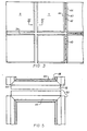
- Figure 3 of the drawings shows several of such units 11 mounted on a suitable mullion frame (not shown).
- a gap is formed between adjacent sides of the units 11 and this gap is preferably closed by means of the weather seal 34.
- the weather seal has not been put in place in order to illustrate the elongate clamping bars 40 used to attach the sealed units to the mullion frame.
- Bolts 42 or other suitable fasteners are used to attach the clamping barto the mullion frame. These bolts 42 extend into holes in the mullion frame as will be explained hereinafter with reference to Figure 4.
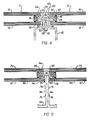
- each device 44 joins and seals the edge portions of the glass plates 10 and 12 and part thereof is located between these glass plates.
- Each device 44 comprises a first section 46 forming a substantially enclosed, elongate cavity for holding dessicant, which section is positioned between the two glass plates 10 and 12 adjacent the edges 48 and 50 thereof.
- the spacer device also has a second section 52 in the form of an integral extension of the first section projecting outwardly to a position 53 beyond the adjacent edges 48 and 50 of the glass plates.
- the second section 52 is made from a thicker metal than the major portion of the first section 46.
- the spacer device is preferably constructed from aluminum and the device is shaped as required by an extrusion process.
- a third section 54 which is an integral extension of the first section 46 and which projects outwardly . away from the center of the sealed unit to a location directly between the adjacent edges 48 and 50.ofthe glass plates.
- a structural sealant 56 which preferably is a two part, fast cure silicone sealant. This type of sealant does not break down under ultraviolet light.
- Each of the two spacer devices 44 is clamped to the end of the mullion frame 45 by means of the clamping bar 40 and bolts 42. If necessary, a suitable cutout can be provided on the outer end of the section 52 to permit passage of the bolts 42. Threaded holes 58 are formed in the mullion frame to receive the bolts 42.
- An optional glass seat (not shown) can be provided between mullion frame 45 and each plate 12 if desired.
- the preferred dessicant material is molecular sieve. Instead of using dessicant material such as that shown, it is possible to use a light gas such as argon or argon-halocarbon mixture in the space between the glass lights. Such a gas will not form condensation in the interior of the unit. The use of such gases is well known in the art.
- moisture barrier sealant 62 also called the vapour seal.
- the preferred sealant 62 is polyisobutylene which is a viscous material which remains viscous during the life of the sealed unit.
- the silicone seals 56 and the structural spacer devices 44 in this embodiment and those described hereinafter should be constructed and arranged to minimize the movement of the vapour seal 62. This can be accomplished by making the hollow first section 46 slightly flexible and by making each silicone seal 56 relatively wide, preferably approximately 8 mm., and relatively thin in the direction perpendicular to the glass plates, preferably approximately 3 mm.
- the seals should have parallel sides, should not be thinner than 2.5 mm., and should be made with a high modulus silicone.
- the overall stress on the spacers in units constructed in accordance with this invention are not significantly greater than stresses in the spacers of typical capped' units because temperature and pressure loads (i.e. inside loads) are usually greater than wind suction loads (outside loads).
- each connecting spacer device 74 joins and seals the edge portions of the two glass plates that make up each unit.
- Each device 74 comprises a first section 76 that forms a cavity for holding dessicant in the same manner as the first section 46 of the embodiment shown in Figure 4.
- the first section 76 extends to a location directly between the edges of the glass plates.
- the spacer device 74 also has a second section 78 in the form of an integral extension of the first section 76 and this second section comprises all of the portion of the device 74 located outside the space between the two glass plates. Again the second section 78 is thicker than the material forming the first section 76.
- the second section 78 has first and second legs 82 and 84 with the second leg being considerably longer than the first leg.
- the first leg 82 extends from the first section 76 parallel to the glass plates to a position located out from the adjacent edges of the glass plates.
- the second leg 84 extends perpendicularly from the first leg and past the adjacent edge 80 of the inner light to a location beyond the plane of the outer surface 86 of the inner light.
- the second section 78 also has a third leg 88 that extends perpendicularly from the end of the second leg that is furthest from the first leg 82. If desired the two second legs 84 can be connected to one another to provide stability and support.
- the spacer devices 74 will typically only be used on two opposite sides of a sealed unit.
- the second leg 84 can be bonded to the adjacent edge 80 of the inner light by structural sealant 90. Further structural sealant 92 is provided between the first section 76 and the inner surface of the outer light 70. It will thus be appreciated that the spacer device 74 provides direct structural support for both the inner and outer lights.
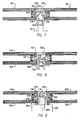
- the first sections 46 and 76 each have two sides 94 that extend generally parallel to the major surfaces of the glass plates.
- the portion of the side 94 closest to the edge of the adjacent glass plate is flat but the side bends outwardly at 96 towards the adjacent glass plate. This bend in each side forms a cavity between the flat portion of the side 94 and the adjacent glass plate, which cavity is suitable for the reception of the structural sealant.
- the glass plates of the unit 98 are connected to a mullion frame (not shown) by means of a spacer device 102.
- the device 102 includes a first section 104 forming the dessicant-holding cavity and located between the two glass plates.
- the device 102 has a second section 106 in the form of an integral extension of the first section and comprising first and second legs 112 and 114.
- the second section 106 first projects outwardly to a position beyond the glass edges 108 and 110 and then inwardly past the edge 108.
- the second leg 114 may be extended (as shown by the dashed lines 116) into a third leg similar to that shown in Figure 6. Again the second leg 114 is connected to the edge 108 by structural sealant 118.
- FIG. 7 there is a third section 120 in the form of an integral extension of the first section 104.
- This third section has a primary leg 122 parallel to the glass plates and extending to a position out from the edges 108 and 110 of the glass plates and a secondary leg 124 extending perpendicularly from the primary leg and along the adjacent edge 110.
- the secondary leg 124 is bonded to the adjacent edge 110 by structural sealant 126.
- a weather seal 128 bridges the gap between the secondary leg 124 and a similar adjacent leg.
- the connecting spacer device 130 has a first section 132 with a cavity for holding dessicant and a second section 134, which is either an integral extension of the first section or a separate element, projecting outwardly to a position 136 beyond the adjacent edges of the glass plates.
- a third section 138 integral with the section 132 which projects to and ends at a location directly between the adjacent edges of the glass plates.
- the third section 138 is bonded to the adjacent glass plate 140 by structural sealant 142.
- Located between the second section 134 and the inner surface and edge of the glass plate 144 is a glass seat 146.
- the second section has a first leg extending from the first section 132 parallel to the glass plates to the aforementioned position 136.
- the second section also has a second leg 148 extending perpendicularly from the first leg and past the adjacent edge of the glass plate 144 to a location beyond the plane of the outer surface of the glass plate 144.
- a flange 150 extends from one side of the second leg 148 along the outer surface of plate 144.
- the flange 150 is an integral part of the spacer device 130. Again a weather seal at 152 is provided to bridge the gap between adjacent sealed units.
- the spacer devices along adjoining edges of adjacent sealed units differ in a manner which permits them to be interconnected to each other.
- the right spacer device 154 joins and seals the edge portions of the glass plates 155 and 156.
- the left spacer device 158 joins and seals the edge portions of the glass plates 159 and 160.
- Each of the spacer devices 154 and 158 has a first section forming an elongate cavity for holding dessicant.
- a second section 162 of the right spacer device is an integral extension of the first section, projects parallel to the major surfaces of the glass plates, and is positioned midway between the planes defined by the outer surfaces of plates 155 and 156.
- the second section projects outwardly to a position between the adjacent edge portions 163 and 164 of the plates 159 and 160.
- the section 162 also has holes formed therein for the reception of threaded fasteners 166. These fasteners extend through holes in a spacer 168 and into threaded holes in the mullion frame 170.
- the left spacer device 158 has a second section 172 in the form of an integral extension of the first section projecting outwardly to a position directly between the edges of plates 159 and 160.
- the left spacer device also has a third section 174 in the form an integral extension of the first section projecting outwardly to a position directly between the edges of the plates 159 and 160.
- a channel-shaped recess 176 Formed between the second and third sections 172 and 174 is a channel-shaped recess 176 that is open along the edge of the sealed unit. It will be appreciated that the second section 162 of the right spacer device forms connecting means for fastening the left spacer device 158. The second section 162 provides a flat end portion 178 with a thickness substantially equal to the width of the recess 176. When the sealed unit of plates 159 and 160 is to be installed in place, the recess 176 is slid over the flat end portion 178.
- the sealed unit of plates 159 and 160 is adapted to be held in place and supported on an adjoining support member or frame 170 by the combination of the spacer device 158 and connecting means in the form of an integral extension of the spacer device of an adjoining sealed unit.
- Each spacer device 186 has a first section 187, which section is positioned generally between the glass plates and a second section 188 which, as before, in an integral extension of the first section and which projects outwardly to a position beyond the adjacent edge 190 of the interior light 184.
- the second section includes a first leg 192 and a second leg 194 perpendicular to the first leg.
- the two adjacent second legs 194 are clamped to the mullion frame 198 by a clamping bar 200.
- the spacer device 186 shall be considered as projecting from the side of the sealed unit even though only the second leg 194 projects beyond the edge 201 of the outer light.
- the embodiment shown in Figure 11 has a spacer device with no dessicant-receiving cavity.
- the spacer device 202 in cross-section comprises at least three parts integrally connected together.
- the second part 206 extends perpendicularly from the inner end of the first part 204 and the third part 208 is connected to the second part and extends parallel to the first part to a position beyond the adjacent edges of the glass plates.
- Structural sealant 214 bonds the first and third parts to the inner surfaces of the adjacent glass plates.
- a compound 216 Immediately adjacent to the inside surface of the second part 206 is a compound 216 capable of providing a dessicant and a vapour seal.
- This compound extends between the glass plates and it can be held in place by a flange 218.
- the compound 216 can be that marketed by Tremco which comprises dessicant impregnated butyl.
- the third parts 208 are clamped to the mullion frame 210 by clamping bar 212.
- each sealed unit comprises three spaced apart glass plates, that is the units connected to the mullion frame by the spacer device 220 are tripled glazed units.
- the device 220 has a first part 222 extending parallel to the glass plates and disposed entirely and directly between adjacent portions of the exterior glass plate 224 and the interior glass plate 225. It also has a second part 226 extending perpendicularly from the inner end of the first part.
- a third part consists of a series of five legs 231 to 235, each of which is perpendicular to the adjacent leg or legs.
- the leg 231 is connected to the second part 226 and extends parallel to the first part to a position beyond the edge of plate 230.
- a glass seat 236 which is held in place by the legs 231, 232 and 233.
- Structural sealant 237 firmly fastens the fifth leg 235 to the inner surface of the plate 225. Also it is the fifth leg 235 that is clamped to the mullion frame by the clamping bar 238.
- the glass plates 224, 225, and 230 are arranged first in their respective relative positions and the compound 216 is applied. The spacer devices 220 are then attached while their ends are unconnected to one another.
- the structural spacer 240 shown in Figure 13 is similar to that shown in Figure 11 and is clamped to a mullion frame in the same manner.
- the device in cross-section has three parts integrally connected together including a first part 241 extending parallel to the glass plates and disposed entirely between adjacent edge portions 242 of the plates.
- a second part 243 extends perpendicularly from the inner end of the first part and is spaced inwardly from the edges of the plates.
- a third part 244 is connected to the second part and extends parallel to the first part to a position beyond the adjacent edges of the glass plates.
- Structural sealant 245 bonds the first and third parts to the glass plates.
- spacer member 246 positioned adjacent to the spacer device 240 on the side of the second part 243 furthest from the adjacent edges 247 and 248 of the glass plates.
- the spacer member 246 forms a substantially enclosed elongate chamber for holding dessicant and can be held in place by the sealant 245.
- the spacer device 250 comprises two separate members securely fastened together.
- This embodiment allows "standard” manufacturing techniques to be used in the construction of the unit. It has the further advantage of permitting the sealed unit to be fixed in place from the interior of the building if required.
- the first member 252 forms a substantially enclosed, elongate cavity 253 for holding dessicant.
- the first member also has means on the outer wall 254 for holding the second member 256. While the first member 252 is located entirely between the glass plates, the second member extends outwardly from the first member to a position beyond the adjacent edges of the glass plates.
- the holding means of the first member 252 define an elongate slot 258 which is wider at the bottom than at the mouth thereof.
- the second member 256 has an anchor portion 260 adapted to be inserted in "snap" fashion in the slot 258 and too wide to be pulled through the mouth of the slot.
- the second member may be constructed in any manner suitable for connecting the spacer device to the adjoining frame.
- the illustrated second member extends past the edge of the interior light to a flange 263 and beyond.
- the flange 263 extends parallel to the outer surface of the interior light and is close to this outer surface.
- a glass seat 264 is inserted between the flange 263 and the edge portion of the interior light.
- structural sealant 266 bonds the exterior surfaces of the holding means to the glass plates on opposite sides of the first member 252.
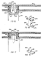
- FIGs 15 and 16 illustrate another form of combination that can be used to provide a structural spacer capable of supporting a sealed glass unit.
- each spacer device 269 is constructed in essentially the same manner as the left spacer device 158 in Figure 9.
- each device forms a channel-shaped recess 270 that is open aong the edge of the unit.
- H-shaped connectors 271 are provided to fasten adjoining spacer devices to the mullion frame 272. Typically these connectors can be spaced apart 6 inches or so with the spacing based upon wind suction design load.
- the construction of each connector 271 can be seen clearly from Figure 16.
- the connector includes a stem portion 272 having a square or rectangular cross-section, and two generally flat arms 273 projecting perpendicularly from one end of the stem portion 272.
- Each of these flat arms has a thickness indicated by the arrow T slightly less or substantially less than the width of the aforementioned recess 270.
- the top surface of the arms 273 is separated by a groove or slot 274 into which the end of a standard screwdriver or other suitable tool can be inserted for rotating the connector about a longitudinal axis extending through the center of the stem portion 272.
- Extending outwardly from the bottom end of stem portion 272 are hook members 276.
- Each hook member has an upwardly extending lip 278 adapted to snap under another lip 280 formed in the mullion frame as shown in Figure 15.
- the complete sealed units 282 are put in the required position on the mullion frame and are set on setting blocks in the conventional manner. At this time there is an open gap 284 between the sealed units and the connectors 271 can be inserted through this gap when the arms 273 extend parallel to the edges of the sealed units.
- a slot is provided in the mullion frame to accommodate the bottom end of the connector therein. The width of the connector indicated by the arrow W in Figure 16 is less than the width of this slot in the mullion frame. After insertion of the bottom end of the connector into the slot, it is then possible to turn the connector by inserting a screwdriver in the slot 274 so that it is brought to the position shown in Figure 15.
- the hook members 276 are locked into the mullion frame.
- the arms 273 extend into the two opposing recesses 270.
- the arms act to clamp the sealed unit to the mullion frame via the spacer device.
- Glass seats 285 are provided between the interior light of each sealed unit and the mullion frame. After the connectors have been installed, the gap 284 can be closed by means of a weather seal material 286.
- FIG. 17 is similar to that shown in Figure 15.
- the spacer devices 269 of the sealed units are exactly the same as are the glass seats 285.
- Extending between the adjacent spacer devices at intervals of about 6 inches are flat, elongate metal plates 287, the construction of which can be seen clearly from Figure 18.
- Located in the center of each plate is a hmole 288 for receiving a threaded fastener 289.
- the plate 287 rests on a spacer sleeve or bar 290 through which extends a hole for passage of the fastener 289.
- the aforementioned plate 287 is sufficiently narrow that it can be inserted through the gap 284 between the edges of the sealed units.
- the plate can then be turned 90° into the recesses 270 of the spacer devices.
- a nib is provided in the bottom of each plate 287 and this nib locates a groove in the spacer 290 at the correct rotation. If a nib and groove are used, then the spacer 290 should be an integral part of the mullion.
- the end portions 291 of each metal plate have a thickness slightly less or substantially less than the width of the recesses 270. The thickness of the end portions is such that a sliding fit is preferably formed between these end portions and the two spacer devices connected thereto. If desired each end portion 291 can be bevelled as shown to permit easy insertion into the recesses 270.
- the plates 287 are adapted to clamp the sealed units to the frame via the spacer devices 269.
- FIGs 19 and 20 illustrate structural spacer devices constructed in accordance with the present invention which permit the glass units to be installed from the interior of the building. This is particularly advantageous when the sealed units must be installed on the upper floors of high buildings where scaffolding cannot be employed.
- the spacer devices 269 are constructed in the same manner as earlier described embodiments such as those illustrated in Figures 15 and 17. Thus each spacer device provides a channel-shaped recess 270 that is open along the edge of the unit.
- the left hand sealed unit 292 shown in Figure 19 is connected directly to the mullion frame 293 which is formed with an integral hook 294, the flat end of which fits snugly in the recess 270. If desired the flat end of the hook 294 can be bevelled at 295 to permit easy insertion.
- a glass seat 296 is provided between the outer surface of the interior light and the mullion frame.
- the left hand edge of each sealed unit is mounted in a different manner than the right hand edge.
- the left hand edge of the unit 297 can be seen in Figure 19.
- This edge is connected by means of substantially L-shaped metal plates 298, each of which has a flat end portion 299 provided by one leg.
- the plate 298 can be a continuous plate along each edge of the unit if desired or there can be a number of individual plates 298 along each edge.
- a hole for the passage of a threaded fastener 300 is formed in the other leg of the connector.
- a locating tab 301 can be formed on the mullion frame to properly orient the plate 298 if desired.
- the gap between the mullion frame and the outside surface of the interior light can be filled in by means of a suitable channel member 302 and a glass seat 303.
- the innermost side of the channel 302 is held by an integral clip 304 formed on the outwardly facing surface of the mullion frame.
- the spacer devices 269 are the same as those shown in Figure 19 and previous figures.
- the sealed units are connected to a mullion frame 305 by H-shaped connectors or clips 306.
- the connectors 306 are constructed in the same manner as the connectors 271 shown in Figure 15 except that they are provided with means on their inner ends to permit rotation about their central axis.
- Prior to installation of the sealed units there is a passageway through the mullion frame provided by openings 307 and 308 and the cavity 309 in the frame.
- the cover plate 310 is detached from the mullion frame.
- each connector can be rotated about the central axis of its stem so that the arms are brought into engagement with the recesses.
- the hook members 312 are snapped over the inwardly directed lips 313 of the mullion frame.
- each of the required cover plates 310 can be attached to the innermost wall of the frame 305.
- the weather seal 314 can be applied from the exterior of the building without difficulty in a well known manner.
- FIG 21 illustrates how a structural spacer constructed in accordance with the present invention can be used in conjunction with an insulated panel such as a spandrel glass panel.
- Each spandrel unit 316 has a glass light 317 forming the outside surface, an insulating space 318 and an insulating panel 319 having dimensions lengthwise and widthwise similar to those of the glass plate.
- a structural spacer device 320 constructed in essentially the same manner as the spacer devices 44 shown in Figure 4 joins the light 317 to the panel 319.
- Structural sealant is provided at 321 to join the spacer device to the light 317 and the panel 319.
- a reflective material 322 is applied along the inside surface of the light 317 so that the panel 319 can not be readily seen by an outside observer.
- Each of the panels 319 can be constructed with the use of two, spaced apart metal sheets separated by a layer of polyurethane or polyethylene 328. Insulating panels of this nature are well known as building products.
- the preferred metal for sheets 329 is either aluminum or steel.
- a spacer device 330 has a channel-shaped recess 332 that is open along the edge of the unit.
- Structural sealant 334 is located on two opposite sides of the device 330 and this sealant bonds each of the sides to an adjacent inside surface of a respective glass plate.
- the spacer device 330 which is generally U-shaped, has small longitudinal flanges 336 that extend perpendicularily from each of the opposite sides and towards the adjacent glass plate. These flanges help to secure an elongate strip of compound 338 extending between the glass plates and immediately adjacent to the surface of the device 330 which faces toward the centre of the sealed unit.
- the compound 338 is capable of providing both a dessicant and a vapour seal and can be the same compound as the compound 216 used in the embodiment of Figure 11.
- the preferred material is dessicant impregnated butyl that adheres to the inside surfaces of glass plates and is capable of continuing to adhere to either glass plate in the event the structural sealant 334 should fail.
- the compound 338 preferably extends around and covers the flanges 336. Thus the edge of each flange does not come into contact with the adjacent glass plate.
- the sealed units of Figure 22 are connected to the mullion frame 340 by means of clips 342,which can be of the same construction as that shown in Figure 18. These clips clamp the sealed units to the mullion frame by means of threaded fasteners 344.
- a glass seat 346 is arranged between the edge of the sealed unit and the mullion frame before the sealed unit is claimped into place.
- the preferred compound 338 such as a combination of butyl rubber and polyisobutylene is a fluid material and it can be sized and shaped so that in the event that the structural sealant should fail, the compound 338 will flow and remain adhered to the glass surface. The end result is that the air space between the glass plates remains sealed.
- the outer light 348 If a high negative wind load acts on the outer light 348, the light will move relative to the inner light 350 and thereby increase the volume of the air space between the two lights until the pressure is equalized on both sides of the outer light 348. At this point the outer light will be carrying virtually no load and the inner light 350 which is mechanically held will carry the majority of the wind load. Thus the outer light should remain in place if the sealant 334 has failed.
- the spacer devices 330 are preferably made from extruded aluminum which is notched and cut to length.
- the spacer device 330 can be clear anodized for good long term adhesion and low friction with the clip 342.
- the next step in the manufacturing process is to roll the compound 338 onto the spacer device which at this stage has a length equal to the sum of the length of the four sides of the unit.
- the aforementioned notching is carried out in order to permit the device to be bent into a rectangle.
- the butyl compound 338 is fused at the previously unconnected fourth corner.
- the bent spacer device is jigged so that it is square and is placed on one light of glass.
- the second light of glass is then put in place and the entire unit is rolled through a heated roller press.
- the silicone structural sealant 334 is then put in place by means of a suitable caulking gun and nozzle.
- FIG. 23 of the drawings A variation on a construction shown in Figure 22 is illustrated in Figure 23 of the drawings.
- the exterior light 348 will still normally be held in place.
- the inside light 350 is held in place by mechanical means which include the spacer device 330, clips 342 and threaded fasteners 344.
- the exterior light 348 is normally held in place by the structural sealant 334 as well as the aforementioned compound 338.
- the embodiment of Figure 23 differs from that shown in Figure 22 in that the weather seal 352 has pressure equalization holes 354 distributed along its length and on each side of the sealed unit.
- the provision of these holes means that the pressure on the inside of the outer light 348 and in a bar chamber 356 will be equal with the pressure on the outside of the building in the event of total seal failure as indicated at 358.
- the air seal 346 between the inner light 350 and the glazing bar 360 should be a good air seal although not necessarily perfect.
- partitions 362 should be located at the corner of each lite. Each of these partitions extends tranversely across the bar chamber 356 and the effect of the partitions is to isolate the air into pressure compartments. This can be accomplished by the injection of an expandible silicone foam.
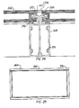
- the sealed units 362 are mounted on a special frame 364 which is shown separately in Figure 25.
- the frame has the same shape and size as the sealed unit which is mounted on one side of the frame.
- the frame is constructed from aluminum and has a hook portion 366. It will be appreciated that the hook portion extends completely around the perimeter of the frame as indicated in Figure 25.
- the hook portion has a L-shape in cross-section and this portion is in the illustrated embodiment connected to a channel portion 368 to construct the complete assembly, the frame 364 is built around the sealed unit 362.
- a flat end section 370 of the hook portion projects into the recess 372 formed by the spacer device.
- the sections of the frame 364 are assembled by means of well known port-hole screws 374 or alternative methods typically used with window frames.
- an air seal 376 is installed between the interior light and the channel portion of the frame.
- FIG. 26 of the drawings Another embodiment employing clips 380 is shown in Figure 26 of the drawings.
- the clips are used to connect sealed units 382 to a mullion frame 384.
- Metal spacer means 386 are similar in their construction to known spacer means but, unlike the known spacers, they are inset from the edges of the unit. Preferably the inset 388 is approximately 1/2" (13 mm). Except for the inset, the manufacture of the sealed units 382 is conventional.
- each clip is provided with glass protective seats 392, one at each end.
- the preferred material for such seats is neoprene. It will be appreciated that each end portion of the clip 380 with the glass protective seat in place must have a thickness less than or equal to the distance between the glass plates.
- the sealed unit 382 is fastened to the mullion frame 384 by insertion of the end portions of a number of clips 380 into the edge recess formed by the inset 388 and by attachment of the clips to the adjoining support member or frame 384.
- a glass seat 394 is preferably provided to protect the inner light.
- the second method involves the use of the well known "due point" apparatus to test the unit.
- pressure testing gas is blown into the unit via a breather tube installed during manufacture. A failure of the seal during this test will not result in glass fallout but by an almost instantaneous pressure drop, indicating failure.
- One method of constructing many of the sealed units, herein described comprises assembling the spacer frame to form a rectangle with either temporary or permanent corner pieces. Each corner is then-dip-soldered at 53 (see Figure 5) in a well known manner to seal the corner and permanently fasten the end of one spacer to the adjoining spacer. The glass plates are then attached to the sealed frame.
Landscapes
- Engineering & Computer Science (AREA)
- Civil Engineering (AREA)
- Structural Engineering (AREA)
- Architecture (AREA)
- Load-Bearing And Curtain Walls (AREA)
- Securing Of Glass Panes Or The Like (AREA)
Claims (14)
Applications Claiming Priority (4)
| Application Number | Priority Date | Filing Date | Title |
|---|---|---|---|
| US06/509,652 US4500572A (en) | 1983-06-30 | 1983-06-30 | Structural spacer glazing with connecting spacer device |
| US509652 | 1983-06-30 | ||
| US583221 | 1984-02-24 | ||
| US06/583,221 US4552790A (en) | 1983-06-30 | 1984-02-24 | Structural spacer glazing with connecting spacer device |
Publications (4)
| Publication Number | Publication Date |
|---|---|
| EP0130438A2 EP0130438A2 (de) | 1985-01-09 |
| EP0130438A3 EP0130438A3 (en) | 1985-09-25 |
| EP0130438B1 true EP0130438B1 (de) | 1989-09-06 |
| EP0130438B2 EP0130438B2 (de) | 1995-11-08 |
Family
ID=27056617
Family Applications (1)
| Application Number | Title | Priority Date | Filing Date |
|---|---|---|---|
| EP84106856A Expired - Lifetime EP0130438B2 (de) | 1983-06-30 | 1984-06-15 | Isolierverglasungskonstruktion |
Country Status (4)
| Country | Link |
|---|---|
| US (1) | US4552790A (de) |
| EP (1) | EP0130438B2 (de) |
| AU (1) | AU564504B2 (de) |
| DE (1) | DE3479679D1 (de) |
Cited By (3)
| Publication number | Priority date | Publication date | Assignee | Title |
|---|---|---|---|---|
| DE3439436A1 (de) * | 1984-10-27 | 1986-04-30 | SCHÜCO Heinz Schürmann GmbH & Co, 4800 Bielefeld | Aussenwand- und dachverglasung |
| FR2854421A1 (fr) | 2003-04-29 | 2004-11-05 | Norsk Hydro As | Element de facade pour l'habillage d'un mur de batiment |
| WO2006078165A2 (en) | 2005-01-21 | 2006-07-27 | Permasteelisa International B.V. | Device and method for fixing glass windows to an outer wall construction |
Families Citing this family (92)
| Publication number | Priority date | Publication date | Assignee | Title |
|---|---|---|---|---|
| IT1202093B (it) * | 1985-08-21 | 1989-02-02 | C C Di Costa & C Srl | Sistema di fissaggio di laster vetrocamera isolante a telai metallici di supporto |
| EP0228641A3 (de) * | 1985-12-20 | 1988-04-06 | Marco Fratti | Zarge mit festem und/oder bewegbarem Flügel für Türen, Fenster und dergleichen |
| AU591293B2 (en) * | 1986-04-28 | 1989-11-30 | Midland Glass Company | Double-paned window securement |
| US4766709A (en) * | 1986-04-28 | 1988-08-30 | Midland Glass Company | Double-paned window securement |
| FR2599405B1 (fr) * | 1986-05-27 | 1991-05-24 | Ouest Sa Vitrages Isolants | Dispositif de securite pour batiment a paroi vitree |
| IT1189582B (it) * | 1986-06-19 | 1988-02-04 | Manfredo Alessi | Vetrate strutturali con giunzioni realizzate mediante sigillanti strutturali ed elementi metallici |
| DE3624491C3 (de) * | 1986-07-19 | 1997-04-24 | Hueck Eduard Gmbh Co Kg | Scheibenhalterung zum Aufhängen von Scheibenfeldern an einer Trägerkonstruktion bei Ganzglas-Fassaden |
| DE3633618A1 (de) * | 1986-07-22 | 1988-02-04 | Gartner & Co J | Rahmenlose verglasung |
| BE1000298A5 (fr) * | 1987-02-10 | 1988-10-11 | Portal S A | Vitre et dispositif pour sa fixation a un support. |
| ATE55796T1 (de) * | 1987-03-05 | 1990-09-15 | Koller Metallbau Ag | Plattenkonstruktion fuer eine fassade oder ein dach. |
| DE3714629C2 (de) * | 1987-05-02 | 1997-08-21 | Johann Henkenjohann | Fassadenwand eines Gebäudes |
| CH673863A5 (de) * | 1987-07-17 | 1990-04-12 | Thermopane Ag | |
| IT1221850B (it) * | 1987-08-07 | 1990-07-12 | Col Diego Da | Sistema di rivestimento a specchiature formantifacciata continua per edifici |
| NL8701895A (nl) * | 1987-08-12 | 1989-03-01 | Tapper Beheer En Management B | Gevelelement uitgevoerd als structurele beglazing. |
| DE3734576A1 (de) * | 1987-10-13 | 1989-04-27 | Conzelmann Flachglas | Haltevorrichtung fuer glasfassaden von gebaeuden |
| DE3740059C3 (de) * | 1987-11-26 | 1998-03-26 | Schueco Int Gmbh & Co | Fassadenverkleidung |
| ES2030822T3 (es) * | 1987-12-09 | 1992-11-16 | Metallbau Koller Gmbh | Estructuras de paneles para la formacion de una fachada o similares en una obra. |
| CA1331851C (en) * | 1987-12-14 | 1994-09-06 | Gerhard Reichert | Insulating multiple layer sealed units and insulating spacers therefor |
| DE3807426A1 (de) * | 1987-12-16 | 1989-06-29 | Gartner & Co J | Brandsicheres verglasungssystem |
| US4912898A (en) * | 1987-12-31 | 1990-04-03 | Holmes Thomas G | Glass butt joints for curtain wall construction |
| FR2630766B1 (fr) * | 1988-04-28 | 1992-07-24 | Saint Gobain Vitrage | Element de vitrage pour facade rideau |
| CH677690A5 (en) * | 1988-08-03 | 1991-06-14 | Michel Kowalski | Double-glazing unit for building facade - has peripheral channel-section open to outside, secured between panes by mastic |
| US4961975A (en) * | 1988-11-14 | 1990-10-09 | Walter Bejnar | Sealed glass unit |
| US4893443A (en) * | 1989-01-18 | 1990-01-16 | W & W Glass Products Ltd. | Sealed double glazing unit |
| IT1229297B (it) * | 1989-04-28 | 1991-08-08 | Poly Eng Co Ltd | Finestra strutturata perfezionata. |
| US5026581A (en) * | 1989-08-03 | 1991-06-25 | Shea Jr John R | Invisible mullion assembly |
| DE3939619C1 (de) * | 1989-10-30 | 1991-06-27 | Josef Gartner & Co, 8883 Gundelfingen, De | |
| EP0431230A1 (de) * | 1989-12-06 | 1991-06-12 | Wehr S.A. | Befestigung für Verglasungen in Vorhangfassaden |
| US5177921A (en) * | 1990-02-16 | 1993-01-12 | Space Biospheres Venture | Low leakage glazing system |
| US5138820A (en) * | 1990-02-16 | 1992-08-18 | Space Biospheres Venture | Low leakage glazing system for space frame structures |
| WO1992001136A1 (fr) * | 1990-07-03 | 1992-01-23 | Bogaert Eugene Albert Jean Luc | Vitrage exterieur colle a paroi double et a fixation mecanique avec coupure thermique |
| US5113628A (en) * | 1990-09-20 | 1992-05-19 | Anthony's Manufacturing Company, Inc. | Railless refrigerator display door |
| USRE35149E (en) * | 1990-09-20 | 1996-01-30 | Anthony's Manufacturing Company, Inc. | Railless refrigerator display door |
| US5097642A (en) * | 1990-09-20 | 1992-03-24 | Anthony's Manufacturing Company, Inc. | Glass refrigerator door structure |
| BE1003942A4 (fr) * | 1990-10-01 | 1992-07-22 | Portal S A | Vitre, procede et outil pour sa fabrication. |
| DE59101574D1 (de) * | 1991-01-10 | 1994-06-09 | Gartner & Co J | Fassadenkonstruktion. |
| CA2041364C (en) * | 1991-04-26 | 1993-09-21 | Glenn Robert Allen | Insulated glass/flush outer surface arrangement |
| IT224785Z2 (it) * | 1991-07-12 | 1996-06-27 | Focchi Giuseppe Di Focchi Ugo | Telaio strutturale ad ingombro ridotto per vetri-camera |
| ATE173523T1 (de) * | 1991-07-26 | 1998-12-15 | Fensterbau Stoll | Halteglied für isolierglasscheiben |
| SE468606B (sv) * | 1991-09-24 | 1993-02-15 | Nils Gunnar Jansson | Foerfarande jaemte anordning foer saekrande av fasadelement av glas |
| WO1993021400A1 (en) * | 1992-04-16 | 1993-10-28 | Farag F Aziz | A stopless butt-joint curtainwall system |
| DE4227889A1 (de) * | 1992-08-22 | 1994-02-24 | Goetz Metall Anlagen | Lackierkabine |
| US5579616A (en) * | 1992-08-26 | 1996-12-03 | Farag; F. Aziz | Panel-securing system |
| US5355645A (en) * | 1992-08-26 | 1994-10-18 | Farag F Aziz | Stopless butt-joint multiple curtainwall system |
| GB9218150D0 (en) * | 1992-08-26 | 1992-10-14 | Pilkington Glass Ltd | Insulating units |
| AT398796B (de) * | 1993-06-08 | 1995-01-25 | Brueder Eckelt & Co Glastech | Isolierglaselement für glasfassaden od.dgl. |
| US5544461A (en) * | 1994-09-30 | 1996-08-13 | Sommerstein; Michael | Panel mounting structure |
| DE4438113A1 (de) * | 1994-10-26 | 1996-05-02 | Eberspaecher J | Brandsichere Halterung mindestens einer Scheibe |
| DE4443132A1 (de) * | 1994-12-03 | 1996-06-05 | Eberspaecher J | Halterung einer eine Gebäudeöffnung abdeckenden Doppel- und Mehrfachscheibe |
| BE1010537A3 (fr) * | 1994-12-22 | 1998-10-06 | Glaverbel | Vitrage multiple et procede de fabrication d'un tel vitrage. |
| GB2296279B (en) * | 1994-12-22 | 1998-04-15 | Glaverbel | A multiple glazing unit and method for its construction |
| WO1997023561A1 (en) * | 1995-12-26 | 1997-07-03 | Asahi Glass Company Ltd. | Resin composition for building materials and double-glazed unit |
| FR2744165A1 (fr) * | 1996-01-25 | 1997-08-01 | Vivet Jean Claude | Double vitrage autonome et porteur |
| DE19642175C2 (de) * | 1996-10-12 | 2002-12-19 | Eckelt Glas Gmbh Steyr | Fenster mit einem Holzrahmen und einer Isolierglasscheibe |
| MXPA99005203A (es) | 1996-12-05 | 2006-07-18 | Sashlite Llc | Unidad de ventana con cristales multiples integrados y montaje de marco y metodo para fabricarlo. |
| ATE292734T1 (de) * | 1998-01-19 | 2005-04-15 | Simon Joseph Kenny | Verglasungssystem |
| US6401428B1 (en) | 1999-10-07 | 2002-06-11 | Bowmead Holding Inc. | Fenestration sealed frame, insulating glazing panels |
| NL1016724C2 (nl) * | 2000-11-28 | 2002-05-29 | Reynolds Architectuursystemen | Vliesgevel en werkwijze voor de vervaardiging daarvan. |
| US6662523B2 (en) * | 2001-06-15 | 2003-12-16 | Sashlite, Llc | Insulating glass sash assemblies with adhesive mounting and spacing structures |
| BR0210440A (pt) * | 2001-06-15 | 2005-06-07 | Sashlite Llc | Caixilho de janela com múltiplos painéis integrados e método para a fabricação do caixilho de janela com múltiplos painéis integrados |
| WO2003016665A1 (de) * | 2001-08-13 | 2003-02-27 | Franz Feldmeier | Profilrahmenkonstruktion mit unterdruckglas |
| US20030084622A1 (en) * | 2001-11-05 | 2003-05-08 | Sashlite, Llc | Components for multipane window unit sash assemblies |
| US6679013B2 (en) | 2001-11-15 | 2004-01-20 | Sashlite, Llc | Window assembly with hinged components |
| SE524721C2 (sv) * | 2002-07-29 | 2004-09-21 | Upglaze Hb | Fästanordning vid glasfasader för montering av isolerglas |
| CN2658254Y (zh) * | 2003-06-30 | 2004-11-24 | 珠海市晶艺玻璃工程有限公司 | 幕墙及屋面玻璃紧固装置 |
| US20060005482A1 (en) * | 2003-07-31 | 2006-01-12 | Bennison Stephen J | Point attachment systems for laminated glass and a process for preparing same |
| NL1028914C2 (nl) * | 2005-04-29 | 2006-10-31 | Hendriks Aluminium Geveltechni | Gevelpaneel. |
| DE202005012108U1 (de) * | 2005-08-02 | 2005-11-24 | Clad Engineering | Verglasungssystem |
| DE202005016444U1 (de) | 2005-10-20 | 2006-02-02 | SCHÜCO International KG | Isolierglasscheibe |
| US20070169427A1 (en) * | 2006-01-24 | 2007-07-26 | Lee David E Iii | Decorative grid system and method |
| EP1936096A1 (de) * | 2006-12-19 | 2008-06-25 | Steindl Glas GmbH | Feuerhemmende Glasfassade |
| DE102007025153B4 (de) | 2007-05-29 | 2010-12-30 | Htk Synerg Ltd. | Rahmen für Isolierglasscheiben |
| US20080313982A1 (en) * | 2007-06-20 | 2008-12-25 | Thornton-Termohlen Group Corporation | Curtain Wall Systems and Methods |
| CN101942954A (zh) * | 2009-07-03 | 2011-01-12 | 贾天民 | 一种可监测和调节修复空腔内压力值的负压式中空玻璃 |
| ES2590380T3 (es) | 2010-05-07 | 2016-11-21 | Technical Glass Products | Dispositivo de montaje para acristalamiento estructural resistente al fuego |
| EP2444579B1 (de) | 2010-10-20 | 2014-05-07 | Cuhadaroglu Metal Sanayi Ve Pazarlama Anonim Sirketi | Vorhangwandsystem, in dem ein spezielles Verbindungssystem für Plattenmaterialien wie Glas, Aluminiumblech usw. verwendet wird |
| KR101524507B1 (ko) | 2010-12-23 | 2015-06-01 | 생-고뱅 퍼포먼스 플라스틱스 코포레이션 | 구조적 글레이징 스페이서 |
| NL1039435C2 (nl) * | 2012-03-06 | 2013-09-09 | Luxlight B V | Verbindingssysteem voor meerlaagsruiten, en een lichtstraat omvattende meerlaagsruiten en een verbindingssysteem. |
| ITPD20120184A1 (it) * | 2012-06-06 | 2013-12-07 | Uniform S P A | Serramento |
| EP2778309A1 (de) * | 2013-03-11 | 2014-09-17 | 3M Innovative Properties Company | Verfahren zur Herstellung von Haftverbindungen |
| DE112014001831T5 (de) * | 2013-04-05 | 2015-12-17 | Advanced Building Systems, Inc. | Opakes Außenwandelement mit verdecktem Rahmen |
| US10202762B2 (en) * | 2014-04-24 | 2019-02-12 | New Jersey Institute Of Technology | Concealed fastener window or curtain wall assemblies |
| US10443234B2 (en) | 2015-02-18 | 2019-10-15 | Erie Architectual Products Inc. | Curtain wall system and components thereof |
| WO2017049609A1 (en) * | 2015-09-25 | 2017-03-30 | Trane Air Conditioning Systems (China) Co., Ltd. | Fixing device for heat exchanger |
| US10562274B1 (en) | 2016-02-22 | 2020-02-18 | Apple Inc. | Glass fastening and sealing systems |
| CA2945338C (en) * | 2016-10-14 | 2021-12-14 | Stouffville Glass Inc. | Dutchy with integrated pressure indicator |
| PL239746B1 (pl) * | 2017-11-23 | 2022-01-03 | Boguslaw Szarejko | Wezel mocujacy zespolone szyby elewacyjne |
| US11885118B1 (en) | 2020-09-02 | 2024-01-30 | CDM Capital Asset Group, Inc. | Gasket for prefabricated wall panel systems |
| CN112780161A (zh) * | 2021-02-05 | 2021-05-11 | 周金华 | 一种装配式隐框幕墙 |
| WO2022266348A1 (en) * | 2021-06-17 | 2022-12-22 | Carlex Glass America, Llc | Glass product |
| CA3256635A1 (en) * | 2022-05-06 | 2023-11-09 | Ddp Specialty Electronic Materials Us, Llc | WATER DRAINAGE PIPE FOR DOUBLE SEAL ASSEMBLY |
| WO2023215079A1 (en) * | 2022-05-06 | 2023-11-09 | Ddp Specialty Electronic Materials Us, Llc | Wall panel module comprising dual gasket assembly |
Family Cites Families (16)
| Publication number | Priority date | Publication date | Assignee | Title |
|---|---|---|---|---|
| US2173649A (en) * | 1937-08-26 | 1939-09-19 | Gen Motors Corp | Multiple windowpane construction |
| US2327974A (en) * | 1942-01-30 | 1943-08-24 | Robert Mitchell Co Ltd | Preformed multipane glazing unit |
| US2589064A (en) * | 1946-02-26 | 1952-03-11 | Libbey Owens Ford Glass Co | Multiple sheet glazing units |
| US2489962A (en) * | 1946-11-29 | 1949-11-29 | Christopher L Hardwick | Oven door |
| US2708774A (en) * | 1949-11-29 | 1955-05-24 | Rca Corp | Multiple glazed unit |
| US2933780A (en) * | 1955-08-24 | 1960-04-26 | Multipane Inc | Multiple pane window units |
| DE1509904A1 (de) * | 1965-08-27 | 1969-09-11 | Ludwig Schweinsteiger | Isolierglasfenstereinheit |
| US3367077A (en) * | 1966-02-15 | 1968-02-06 | Aluminum Fronts Inc | Enclosure structure for buildings |
| DE1972259U (de) * | 1967-08-04 | 1967-11-09 | Rehau Plastiks | Verglasungsprofil fuer isolierglasscheiben. |
| DE2315223A1 (de) * | 1972-05-02 | 1973-11-22 | Siler Ag | Fenster mit einer isolierglasscheibe |
| SE390185B (sv) * | 1974-03-01 | 1976-12-06 | Berthagen N T L | Isolerruta |
| US3971178A (en) * | 1974-03-25 | 1976-07-27 | Ppg Industries, Inc. | Add-on multiple glazing with hygroscopic material |
| SE401385B (sv) * | 1977-01-21 | 1978-05-02 | Eriksson Lars | Distanselement for isolerrutor |
| US4102099A (en) * | 1977-05-11 | 1978-07-25 | Frank Robert Gross | Insulating panel |
| DE7734416U1 (de) * | 1977-11-10 | 1978-02-09 | Schueco Heinz Schuermann Gmbh & Co, 4800 Bielefeld | Fenster mit isolierverglasung |
| US4348435A (en) * | 1980-03-19 | 1982-09-07 | Ppg Industries, Inc. | Primed multiple glazed units for curtainwall systems |
-
1984
- 1984-02-24 US US06/583,221 patent/US4552790A/en not_active Expired - Fee Related
- 1984-06-15 DE DE8484106856T patent/DE3479679D1/de not_active Expired
- 1984-06-15 EP EP84106856A patent/EP0130438B2/de not_active Expired - Lifetime
- 1984-06-29 AU AU30056/84A patent/AU564504B2/en not_active Ceased
Cited By (4)
| Publication number | Priority date | Publication date | Assignee | Title |
|---|---|---|---|---|
| DE3439436A1 (de) * | 1984-10-27 | 1986-04-30 | SCHÜCO Heinz Schürmann GmbH & Co, 4800 Bielefeld | Aussenwand- und dachverglasung |
| FR2854421A1 (fr) | 2003-04-29 | 2004-11-05 | Norsk Hydro As | Element de facade pour l'habillage d'un mur de batiment |
| WO2006078165A2 (en) | 2005-01-21 | 2006-07-27 | Permasteelisa International B.V. | Device and method for fixing glass windows to an outer wall construction |
| JP2008528828A (ja) * | 2005-01-21 | 2008-07-31 | ペルマスティーリザ インターナショナル ビー.ヴイ. | ガラス窓を外壁構造に固定するための装置および方法 |
Also Published As
| Publication number | Publication date |
|---|---|
| EP0130438B2 (de) | 1995-11-08 |
| AU564504B2 (en) | 1987-08-13 |
| EP0130438A3 (en) | 1985-09-25 |
| US4552790A (en) | 1985-11-12 |
| DE3479679D1 (de) | 1989-10-12 |
| EP0130438A2 (de) | 1985-01-09 |
| AU3005684A (en) | 1985-01-03 |
Similar Documents
| Publication | Publication Date | Title |
|---|---|---|
| EP0130438B1 (de) | Isolierverglasungskonstruktion | |
| US4500572A (en) | Structural spacer glazing with connecting spacer device | |
| CA1286158C (en) | Structural interface and weatherseal for structurally bonded glazing | |
| US20240368937A1 (en) | Frame providing restriction of thermal deflection of a vig unit edge | |
| US5490358A (en) | Retainer and weatherseal for structurally bonded glazing | |
| US6889480B2 (en) | Unitary insulated glass unit and method of manufacture | |
| US5546713A (en) | Overlapping framing system for glazing elements | |
| US7562504B2 (en) | Architectural panel fabrication system | |
| US4799344A (en) | Mechanical-adhesion glazing | |
| US4835926A (en) | Spacer element for multiglazed windows and windows using the element | |
| EP0124608A1 (de) | Fenstereinheit. | |
| RU2144118C1 (ru) | Система застекления для зданий | |
| WO1993021400A1 (en) | A stopless butt-joint curtainwall system | |
| JPH0373705B2 (de) | ||
| US4766709A (en) | Double-paned window securement | |
| CA2181010A1 (en) | Building extensions | |
| WO2019072935A2 (en) | FRAME SEALING SYSTEM, CURTAIN WALL SYSTEM, AND METHOD FOR MOUNTING CURTAIN WALL | |
| US4817351A (en) | Glazing system | |
| US3931699A (en) | Glazing system | |
| US5252154A (en) | Gasket system | |
| CA1265705A (en) | Structural spacer glazing | |
| AU591293B2 (en) | Double-paned window securement | |
| US20070028538A1 (en) | Glazing system | |
| EP4198246B1 (de) | Befestigungsvorrichtung für eine befestigungsnut einer isolierenden glaseinheit | |
| EP0740726B1 (de) | Modulares system zum errichten von fassaden |
Legal Events
| Date | Code | Title | Description |
|---|---|---|---|
| PUAI | Public reference made under article 153(3) epc to a published international application that has entered the european phase |
Free format text: ORIGINAL CODE: 0009012 |
|
| AK | Designated contracting states |
Designated state(s): DE FR GB |
|
| PUAL | Search report despatched |
Free format text: ORIGINAL CODE: 0009013 |
|
| AK | Designated contracting states |
Designated state(s): DE FR GB |
|
| 17P | Request for examination filed |
Effective date: 19860306 |
|
| 17Q | First examination report despatched |
Effective date: 19870623 |
|
| RAP1 | Party data changed (applicant data changed or rights of an application transferred) |
Owner name: VISION ENGINEERING & DESIGN INC. |
|
| RIN1 | Information on inventor provided before grant (corrected) |
Inventor name: FRANCIS, GEOFFREY VERNON |
|
| GRAA | (expected) grant |
Free format text: ORIGINAL CODE: 0009210 |
|
| AK | Designated contracting states |
Kind code of ref document: B1 Designated state(s): DE FR GB |
|
| ET | Fr: translation filed | ||
| REF | Corresponds to: |
Ref document number: 3479679 Country of ref document: DE Date of ref document: 19891012 |
|
| PLBI | Opposition filed |
Free format text: ORIGINAL CODE: 0009260 |
|
| 26 | Opposition filed |
Opponent name: JOSEF GARTNER & CO. Effective date: 19900529 |
|
| PUAH | Patent maintained in amended form |
Free format text: ORIGINAL CODE: 0009272 |
|
| STAA | Information on the status of an ep patent application or granted ep patent |
Free format text: STATUS: PATENT MAINTAINED AS AMENDED |
|
| ET1 | Fr: translation filed ** revision of the translation of the patent or the claims | ||
| 27A | Patent maintained in amended form |
Effective date: 19951108 |
|
| AK | Designated contracting states |
Kind code of ref document: B2 Designated state(s): DE FR GB |
|
| REG | Reference to a national code |
Ref country code: GB Ref legal event code: 732E |
|
| EN | Fr: translation not filed | ||
| APAC | Appeal dossier modified |
Free format text: ORIGINAL CODE: EPIDOS NOAPO |
|
| APAC | Appeal dossier modified |
Free format text: ORIGINAL CODE: EPIDOS NOAPO |
|
| EN | Fr: translation not filed |
Free format text: BO 96/14 PAGES: 215, IL Y A LIEU DE SUPPRIMER: LA MENTION DE LA NON REMISE DE CETTE TRADUCTION. LA MENTION DE LA REMISE DE CETTE TRADUCTION EST PUBLIEE DANS LE PRESENT BOPI. |
|
| ET3 | Fr: translation filed ** decision concerning opposition | ||
| REG | Reference to a national code |
Ref country code: GB Ref legal event code: IF02 |
|
| PGFP | Annual fee paid to national office [announced via postgrant information from national office to epo] |
Ref country code: GB Payment date: 20030522 Year of fee payment: 20 |
|
| PGFP | Annual fee paid to national office [announced via postgrant information from national office to epo] |
Ref country code: FR Payment date: 20030618 Year of fee payment: 20 |
|
| PGFP | Annual fee paid to national office [announced via postgrant information from national office to epo] |
Ref country code: DE Payment date: 20030718 Year of fee payment: 20 |
|
| PG25 | Lapsed in a contracting state [announced via postgrant information from national office to epo] |
Ref country code: GB Free format text: LAPSE BECAUSE OF EXPIRATION OF PROTECTION Effective date: 20040614 |
|
| REG | Reference to a national code |
Ref country code: GB Ref legal event code: PE20 |
|
| APAH | Appeal reference modified |
Free format text: ORIGINAL CODE: EPIDOSCREFNO |
|
| PLAB | Opposition data, opponent's data or that of the opponent's representative modified |
Free format text: ORIGINAL CODE: 0009299OPPO |