EP0129021B1 - Umhüllungsvorrichtung für Rundballen in Ballenpressen - Google Patents
Umhüllungsvorrichtung für Rundballen in Ballenpressen Download PDFInfo
- Publication number
- EP0129021B1 EP0129021B1 EP19840104553 EP84104553A EP0129021B1 EP 0129021 B1 EP0129021 B1 EP 0129021B1 EP 19840104553 EP19840104553 EP 19840104553 EP 84104553 A EP84104553 A EP 84104553A EP 0129021 B1 EP0129021 B1 EP 0129021B1
- Authority
- EP
- European Patent Office
- Prior art keywords
- cutting
- wrapping
- web
- wrapping material
- operating lever
- Prior art date
- Legal status (The legal status is an assumption and is not a legal conclusion. Google has not performed a legal analysis and makes no representation as to the accuracy of the status listed.)
- Expired
Links
- 230000007246 mechanism Effects 0.000 title claims description 4
- 238000005520 cutting process Methods 0.000 claims abstract description 64
- 239000000463 material Substances 0.000 claims abstract description 23
- 238000003780 insertion Methods 0.000 claims description 8
- 230000037431 insertion Effects 0.000 claims description 8
- 230000009471 action Effects 0.000 claims description 7
- 238000006073 displacement reaction Methods 0.000 claims description 6
- 230000000284 resting effect Effects 0.000 claims description 2
- 238000007493 shaping process Methods 0.000 claims 4
- 238000003475 lamination Methods 0.000 claims 1
- 238000000034 method Methods 0.000 description 21
- 230000008569 process Effects 0.000 description 21
- 238000000465 moulding Methods 0.000 description 13
- 239000000523 sample Substances 0.000 description 8
- 230000005540 biological transmission Effects 0.000 description 2
- 238000010276 construction Methods 0.000 description 2
- 230000000694 effects Effects 0.000 description 2
- 241000446313 Lamella Species 0.000 description 1
- 238000004026 adhesive bonding Methods 0.000 description 1
- 238000005253 cladding Methods 0.000 description 1
- 230000006835 compression Effects 0.000 description 1
- 238000007906 compression Methods 0.000 description 1
- 230000003247 decreasing effect Effects 0.000 description 1
- 238000000605 extraction Methods 0.000 description 1
- 239000002184 metal Substances 0.000 description 1
- 230000004048 modification Effects 0.000 description 1
- 238000012986 modification Methods 0.000 description 1
- 230000000750 progressive effect Effects 0.000 description 1
- 238000009420 retrofitting Methods 0.000 description 1
- 230000007704 transition Effects 0.000 description 1
- 238000004804 winding Methods 0.000 description 1
Images




Classifications
-
- A—HUMAN NECESSITIES
- A01—AGRICULTURE; FORESTRY; ANIMAL HUSBANDRY; HUNTING; TRAPPING; FISHING
- A01F—PROCESSING OF HARVESTED PRODUCE; HAY OR STRAW PRESSES; DEVICES FOR STORING AGRICULTURAL OR HORTICULTURAL PRODUCE
- A01F15/00—Baling presses for straw, hay or the like
- A01F15/07—Rotobalers, i.e. machines for forming cylindrical bales by winding and pressing
- A01F15/071—Wrapping devices
- A01F15/0715—Wrapping the bale in the press chamber before opening said chamber
-
- Y—GENERAL TAGGING OF NEW TECHNOLOGICAL DEVELOPMENTS; GENERAL TAGGING OF CROSS-SECTIONAL TECHNOLOGIES SPANNING OVER SEVERAL SECTIONS OF THE IPC; TECHNICAL SUBJECTS COVERED BY FORMER USPC CROSS-REFERENCE ART COLLECTIONS [XRACs] AND DIGESTS
- Y10—TECHNICAL SUBJECTS COVERED BY FORMER USPC
- Y10T—TECHNICAL SUBJECTS COVERED BY FORMER US CLASSIFICATION
- Y10T83/00—Cutting
- Y10T83/869—Means to drive or to guide tool
- Y10T83/8776—Constantly urged tool or tool support [e.g., spring biased]
- Y10T83/8782—Stored energy furnishes cutting force
Definitions
- the invention relates to a device that can be attached to a baler for wrapping a round bale from agricultural crop material contained in the forming chamber of the baler with a section of an enveloping web, according to the preamble of claim 1.
- a drive which can be switched on and off is provided for one of the two pull-off rollers of the pull-off device, which is derived from a motor, from a towing vehicle pulling the baler or from another drive device, and comprises a chain drive.
- a belt drive is provided instead of the chain drive, the drive belt of which can be brought into drive transmission engagement with the belt pulleys of the belt drive by a pressure roller carried by a first pivoting control lever and can be deactivated by triggering the pressure engagement of the pressure roller on the V-belt.
- the cutting member consists of an elongated, one-piece knife with an approximately central tip of the envelope, which is attached to a displaceably guided carrier. Acting against the two directions of displacement of the carrier, effective compression springs act on the carrier, which prescribe a rest position for the carrier and with it the cutting element, in which the cutting element is at a distance above the enveloping path plane which the enveloping path occupies in the cutting area during a wrapping process. By means of a second pivot control lever, the cutting member can be lowered against the action of the first group of springs into a cutting end position in which the cutting knife passes through the plane of the enveloping path.
- an operator actuates the first pivoting operating lever in order to switch on the drive for the take-off rollers of the take-off device and to pull off a piece of enveloping web from the supply roller and to feed the material inlet opening to the molding chamber.
- the drive on the take-off rollers can be switched off by returning the first pivoting operating lever to its initial position.
- the wrapping sheet Due to the fact that the wrapping sheet is entrained by the round bale, which usually executes a rotational movement about its longitudinal central axis during the wrapping process with the aid of conveying elements that are effective in the molding space, the wrapping of the round bale takes place by progressive wrapping in the wrapping sheet until a desired degree of wrapping is achieved. This is generally at least about 390 ° wrap angle, but can also e.g. B. 720 ° or 900 ° wrap angle. In the latter cases, the degree of wrapping, without gluing the overlapping winding areas of the wrapping web, ensures that the wrapping web remains firmly on the outer circumference of the round bale when it is ejected from the molding chamber and deposited on the field.
- the wrapping process can be ended by actuating the second pivoting operating lever and cutting the wrapping sheet along with it, the wrapping process.
- the invention has for its object to provide a device of the type specified in the preamble of claim 1, which can be put into operation by actuating a single swivel control lever and automatically ends the wrapping process when a predetermined wrapping degree is reached.
- the device according to the invention enables simple single-lever operation, the wrapping process only having to be started by actuating the pivoting operating lever.
- a measuring process takes place, by means of which a predetermined degree of wrapping for the round bale can be determined and at the end of which the web section enveloping the round bale is automatically cut off from the wrapping web on the supply roll.
- the device With the automatic completion of the wrapping process, the device at the same time returns to a starting position for wrapping a subsequent round bale by actuating the single swivel control lever again. Simultaneously with the simplification of the operation, there is also an increased accuracy of the wrapping, since all bales are wrapped in the wrapping web independently of being observed by an operator with the same degree of wrapping.
- the design of the device according to the invention enables a particularly simple retrofitting of balers with such a device without any noteworthy modification work on the baler and with minimal assembly effort.
- the balers can already be manufactured by the manufacturer without any noteworthy information Additional expenditure for such a later retrofit must be prepared.
- the special design of the cutting element ensures quick and particularly clean cutting of all types of wrapping materials, including mesh-like or lattice-shaped web materials, since the entire area of the cutting line is cut by a real cutting process, which also takes place so quickly that fraying occurs caused by tears due to a non-uniform, simultaneous overall cut.
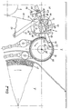
- Fig. 1 illustrates a baler 1 with a molding chamber 2, a crop receiving device 3 in the direction of travel 4 in front of and below a crop entry opening 5 to the molding chamber 2, and conveying elements 6, which transport the harvested crop into the molding chamber 2 up to the completion of the molding process for the to form round bales.
- Balers of this type are known for themselves. Their special design is not important for the wrapping device according to the invention, which can also be connected to balers of a construction other than that shown.
- the wrapping device is designated in its entirety by 7 and, in the installed position on the baler 1, has a position in front of and relatively close above the material entry opening 5. It forms an overall assembly that can be subsequently inserted into the front area of the press housing 8.
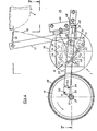
- the wrapping device 7 comprises a supply roll 9 of an endless wrapping web 10 and a take-off device 11 in the form of two take-off rolls 12, 13 which are in constant mutual pressure engagement and which are driven promote the envelope between them together towards the good entry opening. Furthermore, the wrapping device comprises a drive device 14 for the trigger device 11, specifically in the form of a friction gear with two friction wheels 15, 16, which can be moved in and out of mutual frictional engagement by means of a pivoting control lever 17.
- the wrapping device comprises a cutting device 18 which can be actuated towards the end of the wrapping process and which has a cutting element 20 which can be moved transversely to the direction of travel 19 of the wrapping web 10 from its starting cutting position illustrated in FIG , which is arranged in the region between the material inlet opening 5 and the extraction device 11 and is fastened to a carrier 21, on which springs 22 engage.
- the first friction wheel 15 of the friction wheel transmission 14 is fastened on one end of a drive shaft 23 for the conveying elements 6 of the molding chamber 2 of the baling press 1.
- the associated end of the drive shaft 23 is supported in a bearing 24 in a first wall 25 of the press housing 8 and carries the friction wheel 15 on a part 26 projecting outwards beyond the bearing 24.
- the friction wheel 15 rotates continuously with the drive shaft 23 if, for example, during the bale forming process and during the wrapping process. is driven by the towing vehicle for the baler 1.
- one full revolution of the drive shaft 23 and thus of the friction wheel 15 corresponds to an angle of rotation for the round bale 27 or a circumferential angle which, depending on the design of the baler, is, for. B. corresponds to an eighth of the total circumferential angle of 360 °.
- the second friction wheel 16 of the friction gear 14 is fixedly attached to the shaft end of the shaft 12 'of the pull-off roller 12 of the pull-off device 11 and can be pressed from its starting position according to FIG. 2 apart from frictional engagement with the friction wheel 15 in frictional engagement on the friction edge 15.
- the first friction wheel 15 has on its circumference a lining 28 which increases the friction factor, e.g. made of rubber, plastic or the like, and the friction wheel 16 has e.g. a corrugation not illustrated in detail.
- the first friction wheel 15 is assigned a cantilevered, measurable measuring element 29, which in a particularly simple embodiment is designed as a threaded bolt, the threads of which form a measuring section.
- the threaded bolt 29 is in one in the end 26 of the drive shaft 23 coaxially arranged blind threaded bore 30 can be screwed in and fixed in its respective screw-in position by means of a lock nut 31.
- the screw-in position is determined in view of a desired degree of wrapping of the round bale 27 by the wrapping web 10, in such a way that, for example with a wrapping degree of 720 ° wrap angle, the projecting end of the threaded bolt 29 16 full, freely palpable threads in the area between the lock nut 31 and the Provides the outer end of the threaded bolt 29.
- 16 full revolutions of the drive shaft 23 and thus of the threaded bolt 29 correspond to two full revolutions of the round bale 27.
- the shaft ends of the shaft 12 'of the take-off roller 12 are supported in bearings by end bearing plates 32, 33, and the bearing plates 32, 33 are connected to one another via axially parallel connecting means to form a structural unit.
- a sheet metal angle profile 34 can be used as the connecting means, the z. B. with mutually facing inner sides of the bearing plates 32, 33 (not shown in Fig. 5 for reasons of clarity).
- the swivel control lever 17 engages on a swivel shaft 35 which is also mounted in the two bearing plates 32, 33, axially parallel to the take-off rollers 12, 13 and which also serves as a bearing axis for swivel bracket 36 which is freely pivotably mounted on it.
- These swivel brackets 36 support the second pull-off roller 13 via shaft bearings, which can accordingly be moved in a swivel movement about the central axis 37 of the swivel shaft 35 against the pull-off roller 12 in pressure engagement.
- the tension springs 22 serve to bring about constant pressure engagement, the ends of which, opposite the carrier 21 for the cutting member 20, engage the swivel brackets 36.
- the take-off roller 13 is freely rotatably mounted in its shaft bearings on the swivel brackets 36 and receives its rotational movement from the take-off roller 12 as a result of the pressure intervention via the envelope web 10 arranged between the two take-off rollers 12, 13.
- the assembly comprising the bearing plates 32, 33, their connecting means 34 and the parts carried by the bearing plates 32, 33 can be inserted into the wall 25 of the press housing 8 through an insertion opening 38 in the manner of an insert.
- the bearing plate 33 of the structural unit facing away from the friction gear 14 can be firmly connected to an associated second wall 25 'of the press housing 8 of the baling press 1, while the bearing plate 32 facing the friction gear 14 is supported in the insertion opening 38 so as to be horizontally displaceable to a limited extent.
- the insertion opening 38 is at least in the horizontal direction somewhat wider than the bearing plate 32 in this direction, in order to make it possible for the bearing plate 32 to be displaceable from the initial position according to FIG. 2 to the position according to FIG.
- a spring 39 engages on the bearing plate 32 on the side facing away from the friction wheel 15 and serves to hold the bearing plate 32 in its starting position according to FIG. 2 or after a displacement movement in the direction of the friction wheel 15 back into the starting position according to FIG 2 to move back.
- the spring 39 engages with its other end on a pin 40 on the wall 25 of the press housing.
- the carrier 21 for the cutting member 20 is formed by a carrier strip 21 which extends approximately over the width of the enveloping web 10 and parallel to the take-off rollers 12, 13 and on which cranked lever arms 41 which act on the pivot shaft 35 of the pivot control lever 17 and which engage the drive shafts of the take-off rollers 12, 13 overlap.
- the cutting member 20 receives its orientation, as can be seen in particular in FIGS. 2 to 4.
- the cutting member consists of a plurality of approximately triangular knife blades arranged in two rows and fastened next to one another on the carrier strip 21, of which the knife blades arranged in the first row with 42 and those in the second row are designated by 43.
- the knife blades 42 of the first row are arranged at a distance parallel to the surface and offset from the knife blades 43 of the second row, in such a way that the knife blades 42, 43 point with a triangular tip to the enveloping web 10 and - seen in front view - the sharpened cutting edges 44 of the blades 43 of the second row intersect with the cutting edges 44 of the blades 42 of the first row in points that form approximately cutting edge bisection points.
- the distance between the knife blades 42 of the first row and the knife blades 43 of the second row is determined in the exemplary embodiment shown by the thickness of the carrier strip 21, on the rear or front side of which the first and the second row of the knife blades 42, 43 are screwed.
- This special design of the cutting member enables a clean cutting cut, which simultaneously covers the entire width of an enveloping web 10, even when the enveloping web is e.g. has a net or lattice structure.
- the swivel control lever 17, at the upper end of which a pull cord 45 can engage, is firmly connected at its lower end to a lever arm 46, which in turn is connected to a connecting bush 47 on the end of the swivel shaft 35.
- the lever arm 46 At the end facing away from the bushing 47, the lever arm 46 is connected to an angle arm 48, which carries a probe arm 50 on the outside of its leg 49, which is advanced over the plane of the friction gear mechanism 14.
- This probe arm 50 extends into the central region of the friction wheel 15 and is designed as a spring lamella that is only flexible in the transverse direction.
- the probe arm carries at its free end 50 a swivel locking pawl 51 which is fastened to the sensing arm 50 to a limited extent by means of an articulated bolt 52.
- the probe arm 50 has an arcuate limiting slot 53 into which a stop pin 54 engages the pawl 51.
- the arrangement is selected such that when the probe arm 50 moves upward, the pivoting locking pawl 51 can swing out of its locking position, which it assumes in FIGS. 2 and 4, counterclockwise when it hits the measuring member 29 and, after passing through the measuring member 29 in their locking position falls back. If, in the locking position of the swivel locking pawl, it rests on the measuring element 29, it engages with a lower sensing edge 55 in the thread, i.e. the measuring section, of the measuring element 29, while at the same time preventing the sensing arm 50 from moving out of its position in FIG. 4 to return to the starting position according to FIG. 2.
- an angle piece 56 is attached to the wall 25 of the press housing 8, which carries an adjustable stop 57 for the swivel control lever 17.
- This stop 57 forms a thrust abutment on which the pivot control lever 17 bears shortly before reaching its actuation end position, with the result that a continuous pivoting movement of the pivot control lever 17 (in e.g. FIG. 4 clockwise) leads to the entire end on the lever side the assembly and thus the friction wheel 16 is moved in the direction of the friction wheel 15 and the two friction wheels 15, 16 come into drive-transmitting friction.
- an adjustable stop 58 is provided on the lever part 48, which, in engagement with the angle piece 56, limits the starting position of the pivoting operating lever 17 (FIG. 2) and at the same time prevents the assembly from shifting in the direction of the friction wheel 15.
- the above-described wrapping device works as follows: If a round bale 27 has been completed in the molding chamber 2, the pivoting operating lever 17 in FIG. 2 is actuated clockwise starting from the starting position of all parts of the wrapping device 7 illustrated in FIG. 2, e.g. by pulling on the towing line 45. As a result, the device is brought into the state according to FIG. 3. In the position of the parts according to FIG. 3, the swivel control lever 17 has reached its final actuation position, which is defined by the application of the friction wheel 16 on the friction wheel 15.
- This application is brought about by a sliding movement of the bearing plate 32 in the direction of the friction wheel 15 in the insertion opening 38, which is caused by the thrust effect of the swivel control lever 17 resting on the thrust abutment 57.
- the swivel control lever 17 was transferred from its initial position in FIG. 2 to its final actuation position according to FIG. 3, by pivoting the swivel shaft 35, the cutting member 20 of the cutting device 18 has undergone a swivel displacement from its rest position according to FIG. 1 into an end position, which is approximately the later cutting starting position corresponds.
- the tension springs 22 which were already tensioned in the rest position of the cutting member 20 according to FIG.
- the take-off device 11 receives its drive from the friction gear 14, which is maintained until the leading end of the enveloping web 10, which is conveyed by the take-off rollers 12, 13, has reached the material inlet opening 5 and further into the molding chamber and there is now taken from the round bale 27 itself.
- the operator stops pulling on the pull line 45, whereby the parts assume their position as illustrated in FIG. 4 due to the pulling action of the tension springs 22 and also of the tension springs 39.
- the swivel locking pawl 51 rests with its lower contact edge 55 on the threaded bolt 29, with the result that the feeler arm 50 and by this the swivel control lever 17, the swivel shaft 35 and the cutting member 20 are locked in a position which is the starting position for cutting the cutting member 20 corresponds.
- the drive engagement between the friction wheels 15, 16 is interrupted, while together with the drive shaft 23 for the conveying elements 6, the friction wheel 15 and the threaded bolt 29 continue to rotate.
- the swivel locking pawl 51 scans the threads of the threaded bolt 29, as a result of which (FIG. 5) the probe arm 50 progressively bends out until the end of the threaded bolt 29 the swivel locking pawl 51 is released from the last thread turn and allows the probe arm 50 to drop back into the starting position according to FIG. 2. 4, and the cutting element 20 moves under the action of the tension springs 22 in a sudden cutting movement, which is reinforced by the weight of the parts, into the cutting end position according to FIG. 2, severing the envelope on the way.
- the wrapping process is thus completed and the wrapping device is again in its starting position according to FIG. 2, in which it is ready for the execution of a new wrapping process.
- the conveyor drive for the round bale 27 can now be interrupted and the wrapped round bale 27 ejected by opening the molding chamber 2 and placed on the floor.
- the above-described wrapping device is structurally extremely simple and is particularly well suited to the rough agricultural operation. This also applies in particular to the parts 29, 51 etc. which form the measuring and triggering device on the one hand and the locking device for locking the cutting member 20 in its starting position.
- a suitable measuring and triggering device e.g. one that does not determine the degree of cladding depending on the path of the conveying elements 6, but e.g. directly measures the length of a peeled web part and then triggers the locking of the cutting member 20 when a predetermined measuring length is reached.
- the locking device formed by the parts 50, 51 instead of the locking device formed by the parts 50, 51 to provide another z. B. acts on the carrier 21 or its pivot arms 41 and comprises a locking body which is then actuated by the measuring and triggering device.
Landscapes
- Life Sciences & Earth Sciences (AREA)
- Environmental Sciences (AREA)
- Storage Of Harvested Produce (AREA)
- Preliminary Treatment Of Fibers (AREA)
- Auxiliary Devices For And Details Of Packaging Control (AREA)
Priority Applications (1)
| Application Number | Priority Date | Filing Date | Title |
|---|---|---|---|
| AT84104553T ATE33191T1 (de) | 1983-06-18 | 1984-04-21 | Umhuellungsvorrichtung fuer rundballen in ballenpressen. |
Applications Claiming Priority (2)
| Application Number | Priority Date | Filing Date | Title |
|---|---|---|---|
| DE3322024 | 1983-06-18 | ||
| DE3322024A DE3322024C1 (de) | 1983-06-18 | 1983-06-18 | Umhuellungsvorrichtung fuer Rundballen in Ballenpressen |
Publications (3)
| Publication Number | Publication Date |
|---|---|
| EP0129021A2 EP0129021A2 (de) | 1984-12-27 |
| EP0129021A3 EP0129021A3 (en) | 1986-03-05 |
| EP0129021B1 true EP0129021B1 (de) | 1988-03-30 |
Family
ID=6201795
Family Applications (1)
| Application Number | Title | Priority Date | Filing Date |
|---|---|---|---|
| EP19840104553 Expired EP0129021B1 (de) | 1983-06-18 | 1984-04-21 | Umhüllungsvorrichtung für Rundballen in Ballenpressen |
Country Status (5)
| Country | Link |
|---|---|
| US (1) | US4604855A (enExample) |
| EP (1) | EP0129021B1 (enExample) |
| JP (1) | JPS6016524A (enExample) |
| AT (1) | ATE33191T1 (enExample) |
| DE (2) | DE3322024C1 (enExample) |
Families Citing this family (39)
| Publication number | Priority date | Publication date | Assignee | Title |
|---|---|---|---|---|
| JPS60100955U (ja) * | 1983-12-15 | 1985-07-10 | ゲブリユ−ダ−・クラ−ス・ゲゼルシヤフト・ミツト・ベシユレンクテル・ハフツング | 有茎物より成るロ−ル形ベ−ル及びロ−ル形ベ−ル形成機 |
| DE3421427A1 (de) * | 1984-06-08 | 1985-12-12 | Claas Ohg, 4834 Harsewinkel | Rundballenpresse fuer erntegut |
| DE3432251A1 (de) * | 1984-09-01 | 1986-03-13 | Maschinenfabriken Bernard Krone Gmbh, 4441 Spelle | Rundballenpresse fuer landwirtschaftliches erntegut |
| DE3771363D1 (de) * | 1986-03-05 | 1991-08-22 | Deere & Co | Maschine zur bildung von rundballen. |
| EP0235650B1 (en) * | 1986-03-05 | 1991-08-28 | Deere & Company | Machine for forming cylindrical bales of crop |
| DE3617155A1 (de) * | 1986-05-22 | 1987-11-26 | Zweegers & Zonen P J | Rundballenpresse |
| US4677807A (en) * | 1986-07-08 | 1987-07-07 | Deere & Company | System for automatically enveloping a large round bale with a wrapping |
| US4697402A (en) * | 1986-07-08 | 1987-10-06 | Deere & Company | Mechanism for feeding wrap material into a bale-forming chamber for enveloping a large round table |
| DE8627212U1 (de) * | 1986-10-06 | 1986-12-04 | Claas Ohg, 4834 Harsewinkel | Großballenpresse |
| US4779526A (en) * | 1987-02-02 | 1988-10-25 | Deere & Company | Machine for forming cylindrical bales of crop |
| US4781291A (en) * | 1987-08-24 | 1988-11-01 | New Holland Inc. | Netting for wrapping round bales |
| DE3734850A1 (de) * | 1987-10-14 | 1989-04-27 | Zweegers & Zonen P J | Verfahren zum herstellen von erntegut-rollballen sowie vorrichtung zum durchfuehren des verfahrens |
| DE3816219A1 (de) * | 1988-05-11 | 1989-11-23 | Greenland Gmbh & Co Kg | Grossballenpresse |
| GB8814086D0 (en) * | 1988-06-14 | 1988-07-20 | Ford New Holland Nv | Round balers |
| US4938004A (en) * | 1989-03-13 | 1990-07-03 | Ford New Holland, Inc. | Net wrapping method |
| US4896477A (en) * | 1989-03-13 | 1990-01-30 | Ford New Holland, Inc. | Net wrapping apparatus |
| US4956968A (en) * | 1989-12-11 | 1990-09-18 | Ford New Holland, Inc. | Round baler with mechanism for dispensing wrapping material |
| EP0432830B1 (en) * | 1989-12-11 | 1994-12-21 | New Holland Belgium N.V. | Bale wrapping apparatus for round balers |
| US5036642A (en) * | 1989-12-11 | 1991-08-06 | Ford New Holland, Inc. | Bale wrapping apparatus for round balers |
| DE4012741C1 (en) * | 1990-04-21 | 1991-05-29 | Maschinenfabriken Bernard Krone Gmbh, 4441 Spelle, De | Crop baling and wrapping machine - incorporates measuring and release unit with adjuster responding to size of bale |
| DE4012739C2 (de) * | 1990-04-21 | 1995-06-01 | Krone Bernhard Gmbh Maschf | Umhüllungseinrichtung für Rundballen in Ballenpressen |
| DE4012738C1 (de) * | 1990-04-21 | 1991-05-23 | Krone Bernard Maschf Gmbh | Maschine zum Aufnehmen und Pressen von landwirtschaftlichem Erntegut |
| DE4012755C1 (en) * | 1990-04-21 | 1991-10-10 | Maschinenfabriken Bernard Krone Gmbh, 4441 Spelle, De | Hay, straw, grass, etc., bailing press - has inner tensile guide rollers movable into raised, specified guide position |
| US5319899A (en) * | 1992-08-14 | 1994-06-14 | Ford New Holland Inc. | Net severing apparatus for round baler |
| US5448873A (en) * | 1993-02-05 | 1995-09-12 | New Holland North America, Inc. | Net knife for round baler |
| US5433059A (en) * | 1993-04-27 | 1995-07-18 | Agco Corporation | Round bale wrapping |
| CA2228150A1 (en) * | 1995-08-10 | 1997-02-20 | Kurt Ertbolle Madsen | A method and a unit for producing round bales of straw or of like material with film wrapping |
| DE19535478A1 (de) * | 1995-09-23 | 1997-03-27 | Deere & Co | Hüllmittelzufuhrvorrichtung und Ballenpresse |
| US5930980A (en) * | 1996-08-12 | 1999-08-03 | Madsen; Kurt Ertboelle | Method and a unit for producing round bales of straw or of like material with film wrapping |
| US5996312A (en) * | 1998-06-15 | 1999-12-07 | Tai E International Patent And Law Office | Tension adjusting device for a packing machine using plastic film |
| US6021622A (en) * | 1998-06-19 | 2000-02-08 | New Holland North America, Inc. | Round bale wrapping apparatus |
| DE19910555A1 (de) * | 1999-03-10 | 2000-09-14 | Lely Welger Maschinenfabrik Gm | Landwirtschaftliche Rundballenpresse mit einer Wägeeinrichtung |
| US7181900B2 (en) * | 2003-11-21 | 2007-02-27 | Vermeer Manufacturing Co. | Netwrap feed and cut mechanism |
| US7409814B2 (en) * | 2004-09-07 | 2008-08-12 | Vermeer Manufacturing Company | Method of initiating automatic feed of bale wrapping material |
| US8516779B2 (en) | 2011-03-16 | 2013-08-27 | Duratech Industries International, Inc. | Net wrap applicator for large round bales |
| US8820040B2 (en) | 2011-07-01 | 2014-09-02 | Cnh Industrial America Llc | Compression rolls on baler pick up |
| US8800255B2 (en) * | 2011-07-01 | 2014-08-12 | Cnh Industrial America Llc | Arrangement and control of precompression rolls in balers |
| DE102011109899B4 (de) * | 2011-08-10 | 2013-02-21 | Maschinenfabrik Bernard Krone Gmbh | Landwirtschaftliche Rundballenpresse |
| IT202000004612A1 (it) * | 2020-03-04 | 2021-09-04 | Cnh Ind Italia Spa | Imballatrice agricola con coltello per materiale di avvolgimento per ridurre l'avvolgimento sul rotore |
Family Cites Families (12)
| Publication number | Priority date | Publication date | Assignee | Title |
|---|---|---|---|---|
| US807239A (en) * | 1903-12-14 | 1905-12-12 | Mayer M Swaab Jr | Cutting device. |
| US1537980A (en) * | 1922-06-09 | 1925-05-19 | Louis A G Asselin | Drag saw |
| DE583909C (de) * | 1932-05-07 | 1933-09-12 | Fritz Wimmer | Messerkasten fuer Ruebenschnitzelmaschinen |
| US2815626A (en) * | 1953-10-26 | 1957-12-10 | Edlo Inc | Banding machine |
| DE1478162A1 (de) * | 1964-09-29 | 1969-10-09 | Pronzati Dr Attilio | Vorrichtung zur Sicherung der Befestigung des Skischuhes am Ski |
| US3285114A (en) * | 1965-06-21 | 1966-11-15 | Fiber Industries Inc | Doffing device with trigger actuated cutter means |
| JPS5225794B1 (enExample) * | 1971-06-24 | 1977-07-09 | ||
| US4296595A (en) * | 1978-07-27 | 1981-10-27 | M & W Gear Company | Apparatus for wrapping a cover material around round bales |
| US4173112A (en) * | 1978-07-27 | 1979-11-06 | M & W Gear Company | Apparatus for wrapping a cover material around round bales |
| US4409784A (en) * | 1981-04-24 | 1983-10-18 | Sperry Corporation | Method of wrapping roll bales with plastic film |
| US4366665A (en) * | 1981-04-24 | 1983-01-04 | Sperry Corporation | Plastic film dispenser for round baler |
| US4407113A (en) * | 1981-06-15 | 1983-10-04 | Core Grant M | Method and means for wrapping round bales |
-
1983
- 1983-06-18 DE DE3322024A patent/DE3322024C1/de not_active Expired
-
1984
- 1984-04-21 AT AT84104553T patent/ATE33191T1/de active
- 1984-04-21 EP EP19840104553 patent/EP0129021B1/de not_active Expired
- 1984-04-21 DE DE8484104553T patent/DE3470108D1/de not_active Expired
- 1984-05-07 US US06/607,367 patent/US4604855A/en not_active Expired - Fee Related
- 1984-06-18 JP JP59123913A patent/JPS6016524A/ja active Granted
Also Published As
| Publication number | Publication date |
|---|---|
| US4604855A (en) | 1986-08-12 |
| JPH047174B2 (enExample) | 1992-02-10 |
| DE3322024C1 (de) | 1984-08-23 |
| EP0129021A2 (de) | 1984-12-27 |
| EP0129021A3 (en) | 1986-03-05 |
| JPS6016524A (ja) | 1985-01-28 |
| ATE33191T1 (de) | 1988-04-15 |
| DE3470108D1 (en) | 1988-05-05 |
Similar Documents
| Publication | Publication Date | Title |
|---|---|---|
| DE3322024C1 (de) | Umhuellungsvorrichtung fuer Rundballen in Ballenpressen | |
| DE2851035C2 (de) | Erntegut-Rundballenformmaschine | |
| EP0341508B1 (de) | Grossballenpresse | |
| EP0157898B1 (de) | Vorrichtung zum Binden von Rollballen aus landwirtschaftlichem Erntegut | |
| DE3418681C2 (enExample) | ||
| EP0156400B1 (de) | Bindeeinrichtung von Maschinen zum Herstellen von zylindrischen Ballen | |
| DE3879999T2 (de) | Foerderrollen fuer netzgewebespender in rundballenpressen. | |
| DE2645762B2 (de) | Vorrichtung zum Umschnüren eines Rollballens aus landwirtschaftlichem Halmgut | |
| EP0077474B1 (de) | Schneidwerk für Selbstladeerntewagen | |
| DE2826904C2 (enExample) | ||
| DE69015338T2 (de) | Ballenumwickelvorrichtung für Rundballenpressen. | |
| DE3150614A1 (de) | Automatische umschnuerungsvorrichtung an landwirtschaftlichen rollballenpressen | |
| EP0004314B1 (de) | Ballenpressvorrichtung für Kartonagenabfälle | |
| DE3617155C2 (enExample) | ||
| DE2947388C2 (enExample) | ||
| DE2530320C3 (de) | Bindevorrichtung für Wickelballenpressen | |
| DE3445060C2 (enExample) | ||
| DE3024101A1 (de) | Bindegarnbetaetigter abschneider fuer eine rollballen-formvorrichtung | |
| DE2831700C2 (de) | Bindeeinrichtung für landwirtschaftliche Rundballenpressen | |
| EP3300585B1 (de) | Rundballenpresse zum aufnehmen und pressen von landwirtschaftlichem erntegut | |
| DE3002988C2 (enExample) | ||
| EP0858734A1 (de) | Rundballenpresse | |
| DE19720542A1 (de) | Vorrichtung und Verfahren zur Sicherung von Garnenden | |
| DE2831315A1 (de) | Vorrichtung zum umschnueren eines rundballens aus landwirtschaftlichen halmguetern o.dgl. | |
| EP0815719B1 (de) | Rundballenpresse |
Legal Events
| Date | Code | Title | Description |
|---|---|---|---|
| PUAI | Public reference made under article 153(3) epc to a published international application that has entered the european phase |
Free format text: ORIGINAL CODE: 0009012 |
|
| AK | Designated contracting states |
Designated state(s): AT BE CH DE FR GB IT LI NL SE |
|
| PUAL | Search report despatched |
Free format text: ORIGINAL CODE: 0009013 |
|
| AK | Designated contracting states |
Kind code of ref document: A3 Designated state(s): AT BE CH DE FR GB IT LI NL SE |
|
| 17P | Request for examination filed |
Effective date: 19860610 |
|
| 17Q | First examination report despatched |
Effective date: 19870916 |
|
| GRAA | (expected) grant |
Free format text: ORIGINAL CODE: 0009210 |
|
| AK | Designated contracting states |
Kind code of ref document: B1 Designated state(s): AT BE CH DE FR GB IT LI NL SE |
|
| REF | Corresponds to: |
Ref document number: 33191 Country of ref document: AT Date of ref document: 19880415 Kind code of ref document: T |
|
| ITF | It: translation for a ep patent filed | ||
| REF | Corresponds to: |
Ref document number: 3470108 Country of ref document: DE Date of ref document: 19880505 |
|
| ET | Fr: translation filed | ||
| RBV | Designated contracting states (corrected) |
Designated state(s): AT BE CH FR GB IT LI NL SE |
|
| GBT | Gb: translation of ep patent filed (gb section 77(6)(a)/1977) | ||
| RBV | Designated contracting states (corrected) |
Designated state(s): AT CH FR GB IT LI SE |
|
| NLV1 | Nl: lapsed or annulled due to failure to fulfill the requirements of art. 29p and 29m of the patents act | ||
| PLBE | No opposition filed within time limit |
Free format text: ORIGINAL CODE: 0009261 |
|
| STAA | Information on the status of an ep patent application or granted ep patent |
Free format text: STATUS: NO OPPOSITION FILED WITHIN TIME LIMIT |
|
| 26N | No opposition filed | ||
| ITTA | It: last paid annual fee | ||
| EAL | Se: european patent in force in sweden |
Ref document number: 84104553.7 |
|
| PGFP | Annual fee paid to national office [announced via postgrant information from national office to epo] |
Ref country code: SE Payment date: 19950405 Year of fee payment: 12 |
|
| PGFP | Annual fee paid to national office [announced via postgrant information from national office to epo] |
Ref country code: GB Payment date: 19950419 Year of fee payment: 12 |
|
| PGFP | Annual fee paid to national office [announced via postgrant information from national office to epo] |
Ref country code: AT Payment date: 19950427 Year of fee payment: 12 |
|
| PGFP | Annual fee paid to national office [announced via postgrant information from national office to epo] |
Ref country code: CH Payment date: 19950505 Year of fee payment: 12 |
|
| PG25 | Lapsed in a contracting state [announced via postgrant information from national office to epo] |
Ref country code: GB Effective date: 19960421 Ref country code: AT Effective date: 19960421 |
|
| PG25 | Lapsed in a contracting state [announced via postgrant information from national office to epo] |
Ref country code: SE Effective date: 19960422 |
|
| PG25 | Lapsed in a contracting state [announced via postgrant information from national office to epo] |
Ref country code: LI Effective date: 19960430 Ref country code: CH Effective date: 19960430 |
|
| GBPC | Gb: european patent ceased through non-payment of renewal fee |
Effective date: 19960421 |
|
| REG | Reference to a national code |
Ref country code: CH Ref legal event code: PL |
|
| EUG | Se: european patent has lapsed |
Ref document number: 84104553.7 |
|
| PGFP | Annual fee paid to national office [announced via postgrant information from national office to epo] |
Ref country code: FR Payment date: 19990429 Year of fee payment: 16 |
|
| PG25 | Lapsed in a contracting state [announced via postgrant information from national office to epo] |
Ref country code: FR Free format text: LAPSE BECAUSE OF NON-PAYMENT OF DUE FEES Effective date: 20001229 |
|
| REG | Reference to a national code |
Ref country code: FR Ref legal event code: ST |